1
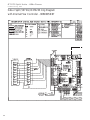
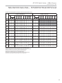
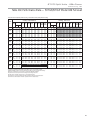
GT-PCS Digital Indoor Split Series (50YGS Models)
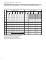
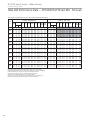
GT-PCS Digital Outdoor Split Series (50YGP Models)
Installation, Operation and Maintenance Instructions
Residential Split
Geothermal Heat Pumps
97B0048N06
Created: 29 Aug., 2013
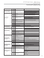
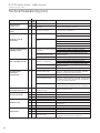
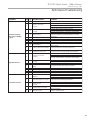
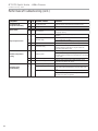
Table of Contents
32-33
4
Hot Water Generator
Module Refrigeration Installation
Outdoor Compressor Section Only
Storage
5
Electrical - Line Voltage
34
Pre-Installation
5
Electrical - Power Wiring
35
Equipment Selection
6
Electrical - HWG Wiring
36
Installation
7-8
Electrical - Low Voltage Wiring
36
Water Connections
8
Thermostat Wiring
37
Integrated Variable-Speed
Water Flow Control
Heat Pump Applications Overview
9
DXM2 Controls
38
DXM2 Layout and Connections
39
Closed Loop Heat Pump Applications
with Internal Flow Controller
10
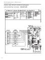
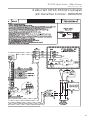
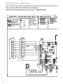
Wiring Diagrams
40-47
Unit Start-Up and Operating Conditions
48-49
Flushing the Earth Loop
11-13
Unit Start-Up Procedure
49-50
Multiple Unit Piping and Flushing
14-16
Unit Operating Conditions
51-52
Ground Loop Heat Pump Applications
17-18
Performance Data
53-56
Closed Loop - External Central Pumping
Applications (Indoor 50YGS Only)
19
Preventive Maintenance
57
Open Loop or Ground-Water
Heat Pump Applications
20-21
Troubleshooting
58-59
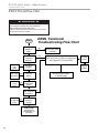
DXM2 Process Flow Chart
60
Water Quality Standards
21
Functional Troubleshooting
61-62
Lineset Information
22
Performance Troubleshooting
63-64
Refrigeration Installation
22-28
Troubleshooting Form
65
Hot Water Generator
29-30
Warranty
66
Revision History
68
Model Nomenclature
3
Safety
Hot Water Generator for Indoor and Outdoor 31
Compressor Section Only
This page was intentionally left blank.
G T- P C S S p l i t U n i t s - 6 0 H z P u r o n ®
Created: 29 Aug., 2013
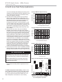
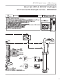
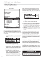
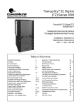
Model Nomenclature: for Indoor Split Series
4 5 6
1 2 3
50
7
8
YGS 0 2 6 N D
9
10
2
11
C 3
12
13
1 1
PREFIX
PACKAGING
1 = Single Pack, Domestic
SERIES (Extended Range
UltraHigh Efficiency)
REVISION LEVEL
1=Current Revision
YGS = Indoor Split Residential
VOLTAGE
UNIT SIZE
3 = 208-230/60/1
026
038
049
064
HEAT EXCHANGER OPTIONS
HWG w/Pump (Standard)
No - HWG
AIR FLOW CONFIGURATION
Copper Cupro-Nickel
C
N
A
J
N= Not Applicable
WATER CIRCUIT OPTIONS
2 = Internal Flow Controller High Head Magna Pump
5 = Motorized Valve (Modulating)
Closed Loop Applications, Low System Pressure Drop
6 = Motorized Valve (Modulating)
Open Loop Applications, High System Pressure Drop
CONTROLS
D=DXM2
In Position 11
12, only the following combinations are available:
9 and 10,
With HWG
Without HWG Description
2C
2A
Internal Flow Controller with Copper Water Coil
5C
5A
Motorized Modulating Valve with Copper Water Coil
6N
6J
Motorized Modulating Valve with Cupro-Nickel Water Coil
Model Nomenclature: for Outdoor Split Series
1 2 3
50
4 5 6
7
8
YGP 0 2 6 N D
9
2
10
11
A 3
12
13
1 1
PREFIX
PACKAGING
1 = Single Pack, Domestic
SERIES (Extended Range
UltraHigh Efficiency)
REVISION LEVEL
1=Current Revision
YGP = Outdoor Split Residential
UNIT SIZE
026
038
049
064
VOLTAGE
3 = 208-230/60/1
HEAT EXCHANGER OPTIONS
A = Non Hot Water Generator with Copper
AIR FLOW CONFIGURATION
N= Not Applicable
WATER CIRCUIT OPTIONS
2 = Internal Flow Controller High Head Magna Pump
CONTROLS
D=DXM2
3
G T- P C S S p l i t U n i t s - 6 0 H z P u r o n ®
Created: 29 Aug., 2013
Safety
Safety
Warnings, cautions and notices appear throughout this
manual. Read these items carefully before attempting any
installation, service, or troubleshooting of the equipment.
DANGER: Indicates an immediate hazardous situation, which
if not avoided will result in death or serious injury. DANGER
labels on unit access panels must be observed.
WARNING: Indicates a potentially hazardous situation, which
if not avoided could result in death or serious injury.
CAUTION: Indicates a potentially hazardous situation or an
unsafe practice, which if not avoided could result in minor or
moderate injury or product or property damage.
NOTICE: Notification of installation, operation or maintenance
information, which is important, but which is not hazardrelated.
WARNING!
WARNING! To avoid the release of refrigerant into the
atmosphere, the refrigerant circuit of this unit must be
serviced only by technicians who meet local, state, and
federal proficiency requirements.
4
WARNING!
WARNING! All refrigerant discharged from this unit must
be recovered WITHOUT EXCEPTION. Technicians must
follow industry accepted guidelines and all local, state,
and federal statutes for the recovery and disposal of
refrigerants. If a compressor is removed from this unit,
refrigerant circuit oil will remain in the compressor. To
avoid leakage of compressor oil, refrigerant lines of the
compressor must be sealed after it is removed.
CAUTION!
CAUTION! To avoid equipment damage, DO NOT use
these units as a source of heating or cooling during the
construction process. The mechanical components and
filters will quickly become clogged with construction dirt
and debris, which may cause system damage.
G T- P C S S p l i t U n i t s - 6 0 H z P u r o n ®
Created: 29 Aug., 2013
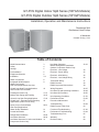
General Information
Storage
Pre-Installation
Inspection
Upon receipt of the equipment, carefully check the shipment
against the bill of lading. Make sure all units have been
received. Inspect the packaging of each unit, and inspect each
unit for damage. Insure that the carrier makes proper notation
of any shortages or damage on all copies of the freight bill
and completes a common carrier inspection report. Concealed
damage not discovered during unloading must be reported
to the carrier within 15 days of receipt of shipment. If not filed
within 15 days, the freight company can deny the claim without
recourse. Note: It is the responsibility of the purchaser to file
all necessary claims with the carrier. Notify your equipment
supplier of all damage within fifteen (15) days of shipment.
Storage
Equipment should be stored in its original packaging in a
clean, dry area. Store units in an upright position at all times.
Stack units a maximum of 3 units high.
CAUTION!
CAUTION! DO NOT store or install units in corrosive
environments or in locations subject to temperature or
humidity extremes (e.g., attics, garages, rooftops, etc.).
Corrosive conditions and high temperature or humidity can
significantly reduce performance, reliability, and service life.
Always move and store units in an upright position. Tilting
units on their sides may cause equipment damage.
CAUTION!
CAUTION! CUT HAZARD - Failure to follow this caution
may result in personal injury. Sheet metal parts may have
sharp edges or burrs. Use care and wear appropriate
protective clothing, safety glasses and gloves when
handling parts and servicing heat pumps.
Unit Protection
Cover units on the job site with either the original packaging
or an equivalent protective covering. Cap the open ends of
pipes stored on the job site. In areas where painting, plastering,
and/or spraying has not been completed, all due precautions
must be taken to avoid physical damage to the units and
contamination by foreign material. Physical damage and
contamination may prevent proper start-up and may result in
costly equipment clean-up.
Examine all pipes, fittings, and valves before installing any of
the system components. Remove any dirt or debris found in
or on these components.
Pre-Installation
Installation, Operation, and Maintenance instructions are
provided with each unit. Horizontal equipment is designed for
installation above false ceiling or in a ceiling plenum. Other
unit configurations are typically installed in a mechanical
room. The installation site chosen should include adequate
service clearance around the unit. Before unit start-up,
read all manuals and become familiar with the unit and its
operation. Thoroughly check the system before operation.
Prepare units for installation as follows:
1. Compare the electrical data on the unit nameplate with
ordering and shipping information to verify that the
correct unit has been shipped.
2. Keep the cabinet covered with the original packaging
until installation is complete and all plastering, painting,
etc. is finished.
3. Verify refrigerant tubing is free of kinks or dents and that
it does not touch other unit components.
4. Inspect all electrical connections. Connections must be
clean and tight at the terminals.
5. Locate and verify any hot water generator (HWG) or
other accessory kit located in the compressor section.
5
G T- P C S S p l i t U n i t s - 6 0 H z P u r o n ®
Created: 29 Aug., 2013
Equipment Selection
The installation of geothermal heat pump units and all
associated components, parts, and accessories which make
up the installation shall be in accordance with the regulations
of ALL authorities having jurisdiction and MUST conform to
all applicable codes. It is the responsibility of the installing
contractor to determine and comply with ALL applicable
codes and regulations.
General
Proper indoor coil selection is critical to system efficiency.
Using an older-model coil can affect efficiency and may
not provide the customer with rated or advertised EER
and COP. Coil design and technology have dramatically
improved operating efficiency and capacity in the past 20
years. Homeowners using an older coil are not reaping these
cost savings and comfort benefits. NEVER MATCH AN R-22
INDOOR COIL WITH AN Puron® COMPRESSOR SECTION.
Newer indoor coils have a larger surface area, enhanced fin
design, and grooved tubing. These features provide a larger
area for heat transfer, improving efficiency and expanding
capacity. Typical older coils may only have one-third to onehalf the face area of these redesigned coils.
6
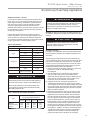
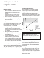
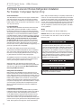
Indoor Coil Selection – GT-PCS (50YGS and 50YGP)
Split system heat pumps are designed for and rated in the
AHRI directory with specific air handlers and cased coils. GTPCS models are rated with FE/FV4 Air Handlers and CNP
Cased coils. Applying these heat pumps to other brands/
models of air handlers or cased coils may result in
unsatisfactory performance and make them ineligible for
the Energy Star program, utility rebates, or tax credits.
See Table 1 in this publication for the AHRI system match.
Table 1: GT-PCS Component Matches for AHRI Ratings
Unit Size
26
38
49
64
Air Handler Model FE/FV4
002
005
006
006
Cased Coil Model CNP
24
36
48
60
Due to limitations in combining a geothermal split unit with a
Carrier Infinity fan coil, furnace or Infinity Control; or a Bryant
Evolution fan coil, furnace or Evolution Control, refer to Service
Bulletins SMB 10-0007 and DSB 10-0007.
G T- P C S S p l i t U n i t s - 6 0 H z P u r o n ®
Created: 29 Aug., 2013
Installation
The installation of geothermal heat pump units and all
associated components, parts and accessories which make
up the installation shall be in accordance with the regulations
of ALL authorities having jurisdiction and MUST conform to
all applicable codes. It is the responsibility of the installing
contractor to determine and comply with ALL applicable
codes and regulations.
Removing Existing Condensing Unit (Where Applicable)
1. Pump down condensing unit. Close the liquid line
service valve of existing condensing unit and start
compressor to pump refrigerant back into compressor
section. Then, close suction service valve while
compressor is still running to trap refrigerant in outdoor
section. Immediately kill power to the condensing unit.
2. Disconnect power and low voltage and remove old
condensing unit. Cut or unbraze line set from unit.
Remove condensing unit.
3. If condensing unit is not operational or will not pump
down, refrigerant should be recovered using appropriate
equipment.
4. Replace line set, especially if upgrading system from
R-22 to Puron® refrigerant. If line set cannot be replaced,
it must be thoroughly flushed before installing new
compressor section. Puron® compressors use POE
oil instead of mineral oil (R-22 systems). Mineral oil is
not compatible with POE oil, and could cause system
damage if not completely flushed from the line set.
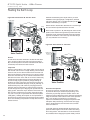
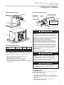
“Indoor” Compressor Section Location
Both “indoor” and “outdoor” versions of the geothermal
split system compressor section are available. “Indoor”
version is not designed for outdoor installation. Locate the
unit in an INDOOR area that allows enough space for service
personnel to perform typical maintenance or repairs without
removing unit. Units are typically installed in a mechanical
room or closet. Never install units in areas subject to freezing
or where humidity levels could cause cabinet condensation
(such as unconditioned spaces subject to 100% outside air).
Consideration should be given to access for easy removal
of service access panels. Provide sufficient room to make
water, electrical, and line set connections.
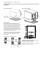
Any access panel screws that would be difficult to remove
after the unit is installed should be removed prior to setting
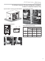
the unit. Refer to Figure 1 for an illustration of a typical
installation. Refer to “Physical Dimensions” section for
dimensional data. Conform to the following guidelines when
selecting unit location:
1. Install the unit on a piece of rubber, neoprene or other
mounting pad material for sound isolation. The pad should
be at least 3/8” [10mm] to 1/2” [13mm] in thickness.
Extend the pad beyond all four edges of the unit.
2. Provide adequate clearance for maintenance and
service. Do not block access panels with piping, conduit
or other materials.
3. Provide access for servicing the compressor and heat
exchanger without removing the unit.
4. Provide an unobstructed path to the unit within the
closet or mechanical room. Space should be sufficient to
allow removal of the unit, if necessary.
5. Provide access to water valves and fittings and
screwdriver access to the unit side panels and all
electrical connections.
“Outdoor” Compressor Section Location
Locate the unit in an outdoor area that allows easy loop
and lineset access and also has enough space for service
personnel to perform typical maintenance or repairs. The
“outdoor” compressor section is usually installed on a
condenser pad directly outside the lineset access into the
building. The loop access end should be located away from
the building. Conform to the following guidelines when
selecting unit location:
1. Provide adequate access for loop trench excavation.
2. Locate unit directly outside lineset penetration if
possible. Utilize existing condenser pad where
possible.
3. Provide access for servicing and maintenance.
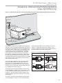
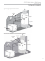
“Outdoor” compressor section may be mounted on a
vibration isolation pad with loop access hole as shown
in Figure 3. When mounting on an existing concrete
condenser pad, 3” [76 mm] holes should be bored through
the pad to accommodate the pipe (1-¼” - 32mm) and
insulation (½” [13mm] wall thickness). Figure 3 illustrates
location and dimensions of the holes required.
Air Handler Installation
This manual specifically addresses the compressor section
of the system. Air handler location and installation should
be according to the instructions provided with the air
handling unit.
CAUTION!
CAUTION! To avoid equipment damage, DO NOT allow
system water pressure to exceed 100 psi. when using the
Internal Flow Controller option. The expansion tank in the
flow controller has a maximum working water pressure of
100 psi. Any pressure in excess of 100 psi may damage
the expansion tank.
7
G T- P C S S p l i t U n i t s - 6 0 H z P u r o n ®
Created: 29 Aug., 2013
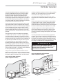
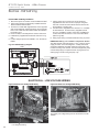
Installation
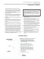
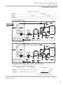
Figure 1: 50YGS Installation
Figure 3: 50YGP Installation
Stainless
Steel
Braided
Connecting
Hoses
Air Pad With
Access Hole
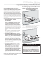
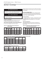
Water Connections
The TTS models utilize swivel piping fittings for water
connections that are rated for 450 psi (3101 kPa) operating
pressure. The connections have a rubber gasket seal similar
to a garden hose gasket, which when mated to the flush
end of most 1” threaded male pipe fittings provides a leakfree seal without the need for thread sealing tape or joint
compound. Check for burrs and ensure that the rubber seal
is in the swivel connector prior to attempting any connection
(rubber seals are shipped attached to the swivel connector).
DO NOT OVER TIGHTEN or leaks may occur.
The female locking ring is threaded onto the pipe threads
which holds the male pipe end against the rubber gasket,
and seals the joint. HAND TIGHTEN ONLY! DO NOT
OVERTIGHTEN!
Figure 2: Water Connections (50YGS Series)
([LVWLQJ3DGODUJHUWKDQ[>[FP@
%RWWRP9LHZ
RI8QLW
µ[µ
[FP
µ
>FP@
µ>FP@
µ
>FP@
Swivel Nut
Stainless steel
snap ring
Hand Tighten
Only!
Do Not
Overtighten!
NOTE: Outdoor Unit Water Connections
50YGP026 and 038 units are shipped with ¾” stainless steel
braided hoses connected to unit piping.
50YGP049 and 064 units are shipped with 1” stainless steel
braided hoses connected to unit piping.
Gasket
Brass Adaptor
8
µ
>FP@
G T- P C S S p l i t U n i t s - 6 0 H z P u r o n ®
Created: 29 Aug., 2013
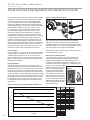
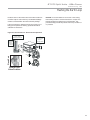
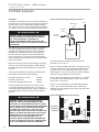
Integrated Variable-Speed Water Flow Control
Heat Pump Applications Overview
Integrated Variable-Speed Water Flow Control is a
revolutionary new, intelligent, and efficient way to circulate
water (or water plus antifreeze) using INTERNAL, variable
water flow control. The factory-installed high-efficiency
variable-speed pump uses 60%-80% less wattage than a
traditional fixed speed pump. Integrated Variable-Speed
Water Flow Control technology improves performance of the
unit by reducing the amount of energy required to optimize
the flow of water throughout a GHP System and also reduces
the space, cost, and labor required to install external water
flow control mechanisms (flow controllers, solenoid and flow
control valves).
Integrated Variable-Speed Water Flow Control Configurations:
1) Internal Flow Controller - For Closed
Loop Applications
This is the most common configuration for closed loops.
With this factory-installed standard option, the unit is
built with an Internal Variable Speed Pump and other
components to flush and operate the unit correctly
(including an expansion tank, flush ports and flushing
valves). The pump speed is controlled by the DXM2
control based on the difference in entering and leaving
water temperatures (ΔT). The Internal Flow Controller
pump includes an internal check valve for multiple unit
installations. A copper water coil is standard with this
option.
Note: Internal Flow Controllers are also very suitable
for multiple unit installations depending on pump
performance requirements.
2) Internal Modulating Motorized Valve – For Large
Closed Loop Applications (external central pumping)
Primarily for use on multi-unit closed loop applications
with central pumping. With this factory-installed option,
the unit includes a low pressure drop modulating
motorized valve that is controlled by the DXM2
microprocessor control based on the difference in the
entering and leaving water temperatures (ΔT). A Copper
Water Coil is standard with this option. The modulating
valve in this option has a higher Cv than the open loop
option. (50YGS Models only)
3) Internal Modulating Motorized Valve - For Open
Loop Applications
For use on open loop applications. With this factoryinstalled, standard option, the unit is built with an
internal modulating motorized valve controlled by
the Communicating DXM2 control board based on
entering and leaving water temperatures (ΔT). A low Cv
modulating motorized valve is used for this application
to provide more precise control against the higher
system pressure differential of open loop applications. A
Cupro-Nickel water coil comes standard with this option.
(50YGS Models only)
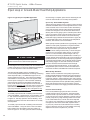
Figure 4a: Typical Closed-Loop Application (with
Internal Flow Controller Shown)
To Thermostat
High and Low
Voltage Knockouts
Internal Flow
Controller
Water Out
Water In
Vibration Isolation Pad
Figure 4b: Typical Open Loop Application (with Internal
Modulating Motorized Valve Shown)
For use on applications using external source for flow
To Thermostat
High and Low
Voltage Knockouts
Internal Motorized
Modulating Valve
Pressure
Tank
Water Out
Water In
Boiler
Drains
Shut Off
Ball Valves
for Isolation
Optional
Filter
Vibration Isolation Pad
CAUTION!
CAUTION! The following instructions represent industry
accepted installation practices for closed loop earth
coupled heat pump systems. Instructions are provided
to assist the contractor in installing trouble free ground
loops. These instructions are recommendations only.
State/provincial and local codes MUST be followed and
installation MUST conform to ALL applicable codes. It is
the responsibility of the installing contractor to determine
and comply with ALL applicable codes and regulations.
Details on these options are included in the following sections
on ground loop and ground water applications.
9
G T- P C S S p l i t U n i t s - 6 0 H z P u r o n ®
Created: 29 Aug., 2013
Closed Loop Heat Pump Applications with Internal Flow Controller
Units with internal flow control come with a built-in variable
speed pump, an expansion tank, flushing ports and threeway valves (used to flush the unit). The variable speed
pump is controlled by the Communicating DXM2 board
based on the difference between the entering and leaving
water temperature (ΔT). For operation outside of the normal
entering water temperature range (50° or 60°F - 110°F
for cooling, 30°F-70°F for heating) the DXM2 controller
may automatically adjust the control ΔT to account for
the abnormal entering water temperatures, maintaining
an appropriate flow rate for proper unit operation. When
entering water temperatures are abnormally low for cooling,
or abnormally high for heating, the DXM2 controller will
maintain a constant leaving water temperature which will
allow the unit to operate properly under those conditions.
The internal expansion tank helps to maintain constant loop
pressure despite the natural expansion and contraction of
the loop as the seasons and loop temperatures vary. The
expansion tank also helps to avoid flat loop callbacks.
Figure 5: Internal Flow Controller
Pre-Installation
Prior to installation, locate and mark all existing underground
utilities, piping, etc. Install loops for new construction before
sidewalks, patios, driveways, and other construction has
begun. During construction, accurately mark all ground loop
piping on the plot plan as an aid in avoiding potential future
damage to the installation.
The following section will help to guide you through flushing a
unit with internal flow control.
Test individual horizontal loop circuits before backfilling.
Test vertical U-bends and pond loop assemblies prior to
installation. Pressures of at least 100 psi [689 kPa] should be
used when testing. Do not exceed the pipe pressure rating.
Test entire system when all loops are assembled.
Piping Installation
The typical closed loop ground source system is shown in
Figures 4a. All earth loop piping materials should be limited to
polyethylene fusion only for in-ground sections of the loop and
it is also recommended for inside piping. Galvanized or steel
fittings should not be used at any time due to their tendency to
corrode. All plastic to metal threaded fittings should be avoided
due to their potential to leak in ground loop applications. Loop
temperatures can range between 25 and 110°F [-4 to 43°C].
Flow rates between 2.25 and 3 gpm per ton [2.41 to 3.23
l/m per kW] of cooling capacity is recommended in these
applications.
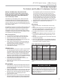
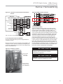
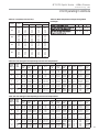
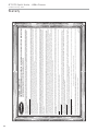
Figure 6: Internal Flow Controller Pump Performance
Water Pressure Schrader Ports
The pressure ports built in to the unit are provided as a
means of measuring pressure drop through the water-torefrigerant heat exchanger. The water pressure ports are
schrader ports smaller than refrigerant schrader ports. They
are the same size as tire schrader ports. A digital pressure
gauge is recommended for taking
Digital Pressure
pressure readings through these
Gauge
ports. The water flow through
the unit can be determined by
measuring the water pressure
at the “water pressure out” port
and subtracting it from the water
pressure at the “water pressure
in” port. Comparing the pressure
differential to the pressure drop in
Table 14 will determine the flow
rate through the unit.
60
50
Head (Ft.)
40
30
20
10
0
0
5
10
15
20
Flow (GPM)
10
25
30
35
40
GPM
Head (ft)
GPM
0.0
1.0
2.0
3.0
4.0
5.0
6.0
7.0
8.0
9.0
10.0
11.0
12.0
13.0
14.0
15.0
16.0
17.0
18.0
19.0
20.0
21.0
44.7
45.4
46.1
46.8
47.5
47.7
47.1
46.1
45.3
43.9
42.6
41.2
39.9
38.7
37.4
36.1
34.9
33.7
32.5
31.3
30.1
28.9
22.0
23.0
24.0
25.0
26
27
28
29
30
31
32
33
34
35
36
37
38
Head (ft)
27.8
26.7
25.6
24.5
23.4
22.3
21.3
20.2
19.2
18.2
17.3
16.3
15.4
14.4
13.5
12.6
11.7
G T- P C S S p l i t U n i t s - 6 0 H z P u r o n ®
Created: 29 Aug., 2013
Flushing the Earth Loop
Once piping is completed between the unit and the ground
loop, final purging and charging of the loop is needed.
A flush cart (at least a 1.5 hp [1.1kW] pump) is needed
to achieve adequate flow velocity in the loop to purge air
and dirt particles from the loop itself. Antifreeze solution is
used in most areas to prevent freezing. All air and debris
must be removed from the earth loop piping system before
operation, Flush the loop with a high volume of water at
a high velocity (2 fps [0.6 m/s] in all piping), using a filter
in the loop return line, of the flush cart to eliminate debris
from the loop system. See Table 2 for flow rate required to
attain 2fps [0.6 m/s]. The steps below must be followed for
proper flushing.
WARNING!
WARNING! Disconnect electrical power source to prevent
injury or death from electrical shock.
Figure 7b: Cam Fittings for Flush Cart Hoses
Attach
to Flow
Controller
Flush Port
Connect
to Flush
Cart Hose
(1 of 2)
Table 2: Minimum Flow Required to Achieve 2 ft/sec
velocity
PE Pipe Size
Flow (GPM)
3/4"
4
1"
6
1 1/4"
10
1 1/2"
13
2"
21
Units with internal variable speed pumps also include a
check valve internal to the pump. It is not possible to flush
backwards through this pump. Care must be taken to
connect the flush cart hoses so that the flush cart discharge is
connected to the “water in” flushing valve of the heat pump.
NOTICE: A hydrostatic pressure test is required on ALL piping,
especially underground piping before final backfill per IGSHPA
and the pipe manufacturers recommendations.
Figure 8a: Valve Position A - Loop Fill/Flush
Loop Fill
Fill loop (valve position A, see Figure 8a) with water from a
garden hose through flush cart before using flush cart pump
to ensure an even fill and increase flushing speed. When
water consistently returns back to the flush reservoir, switch
to valve position B (Figure 8b).
Loop
Isolate expansion tank for flushing procedure using the ball
valve. During dead heading of flush cart pump, isolation will
prevent compression of bladder in the expansion tank and
flush cart fluid level dropping below available capacity.
Out
Flush Port
Figure 7a: Typical Cleanable Flush
Cart Strainer (100 mesh [0.149mm])
Valve Position
In
Front of Unit
Valve Position
11
G T- P C S S p l i t U n i t s - 6 0 H z P u r o n ®
Created: 29 Aug., 2013
Flushing the Earth Loop
NOTICE: Actual flushing time require will vary for each
installation due to piping length, configuration, and flush
cart pump capacity. 3/8” or less fluid level drop is the ONLY
indication that flushing is complete.
Figure 8b: Valve Position B - Unit Fill / Flush
Loop
Valve Position
Switch valves to Position B to flush the unit. Flush through
the unit until all air pockets have been removed.
Move valves to position C. By switching both valves to this
position, water will flow through the loop and the unit heat
exchanger. Finally, the dead head test should be checked
again for an indication of air in the loop. Fluid level drop is
your only indication of air in the loop.
Flush Port
Out
Figure 8d: Valve Position C - Full Flush
Add Antifreeze
Now if Needed
In
Front of Unit
Valve Position
Dead Head
Pump Test
for Air
Loop
Unit Fill
Unit fill valves should be switched to Position B while flush
cart is pumping to fill the unit heat exchanger (see Figure
8b). The valves position should be maintained until water is
consistently returned into the flush reservoir.
Flush Port
Valve Position
Loop Flush
Switch to valve Position A. The supply water may be shut off
and the flush cart turned on to begin flushing. Once the flush
reservoir is full, do not allow the water level in the flush cart
tank to drop below the pump inlet line or air can be pumped
back out to the earth loop. Try to maintain a fluid level in the
tank above the return tee so that air can not be continuously
mixed back into the fluid. Surges of 50 psi [345 kPa] can
be used to help purge air pockets by simply shutting off
the flush cart return valve going into the flush cart reservoir.
This process ‘dead heads’ the pump to 50 psi [345 kPa]. To
dead head the pump until maximum pumping pressure is
reached, open the valve back up and a pressure surge will
be sent through the loop to help purge air pockets from the
piping system. Notice the drop in fluid level in the flush cart
tank. If all air is purged from the system, the level will drop
only 3/8” in a 10” [25.4 cm] diameter PVC flush tank (about
a half gallon [1.9 liters]) since liquids are incompressible. If
the level drops more than this level, flushing should continue
since air is still being compressed in the loop fluid. Do this a
number of times.
Out
In
Front of Unit
Valve Position
Pressurize and Operate
As shown in Figure 8e, close the flush cart return valve
to pressurize the loop to at least 50 psi [345 kPa], not to
exceed 75 psi [517 kPa]. Open the isolation valve to the
expansion tank and bleed air from the expansion tank piping
using the schraeder valve located in front of the expansion
tank. This will allow loop pressure to compress the
expansion tank bladder, thus charging the expansion tank
with liquid. After pressurizing, close the flush cart supply
valve to isolate the flush cart. Move the Flow Controller
valves to Position D.
Loop static pressure will fluctuate with the seasons and
pressures will be higher in the winter months than during
the cooling season. This fluctuation is normal and should
be considered when charging the system initially. Unhook
12
G T- P C S S p l i t U n i t s - 6 0 H z P u r o n ®
Created: 29 Aug., 2013
Flushing the Earth Loop
the flush cart from the Internal Flow Controller. Install Flow
Controller caps to ensure that any condensation/leakage
remains contained within the Flow Controller package.
If the loop pressure is between 50 and 75 psi [345 to 517
kPa] upon completion of flushing, pressures should be
sufficient for all seasons.
NOTICE: It is recommended to run the unit in the cooling,
then heating mode for 15-20 minutes each to ‘temper’ the
fluid temperature and prepare it for pressurization. This
procedure helps prevent the periodic “flat” loop condition of
no pressure.
Figure 8e: Valve Position D - Pressurize and Operation
2
Close to isolate
Internal Flow Controller
3
Close Internal
Flow Controller
Valves for
Operation Mode
1
Dead Head
Pump to
Pressurize
to 50 PSI
Loop
Valve Position
Flush Port
Out
In
Front of Unit
Valve Position
13
G T- P C S S p l i t U n i t s - 6 0 H z P u r o n ®
Created: 29 Aug., 2013
Multiple Unit Piping and Flushing
Often projects require more than one heat pump. Where
possible, it makes sense for multiple units to share a common
ground loop. Common ground loops for multiple units bring
new challenges including the need to avoid backward flow
through inactive units, increased pumping requirements,
and more complex flushing needs. Three types of multiple
unit systems are described below along with guidelines for
installation of each type.
Integrated Variable-Speed Water Flow Control internal
variable flow technology is a great assist for systems with
multiple units and is available in three different configurations:
1. Internal flow controller
2. Internal modulating valve for closed loops
3. Internal modulating valve for open loops
The internal modulating valve for open loops version should
never be used on closed loops.
The internal flow controller version includes an internal
Magna variable speed circulator controlled by the DXM2
microprocessor, internal 3-way flushing valves, an internal
bladder type expansion tank, and front-mounted pressure
ports that allow access to the pressure drop across the
coaxial heat exchanger only. The pump includes an internal
check valve. The pump curve for the circulator is shown
in Figure 6. The internal expansion tank will operate as a
pressure battery for the geothermal system. It will absorb
fluid from the loop when loop pressure rises and inject
fluid into the loop when loop pressure falls. In this way the
expansion tank will help to maintain a more constant loop
pressure and avoid flat loops due to seasonal pressure
changes in the loop.
Pressure drop through the flushing valve can be calculated
using the following formula.
ΔP = (GPM/Cv)2 where,
ΔP = pressure drop in psi through the valve while flushing
GPM = flushing flow in gallons per minute
Cv = valve Cv in flushing mode
We know from Table 3 that the Cv for the flushing valve
in a 50YGS/P026 is 10.3 in the flushing mode (90° flow).
Therefore, ΔP = (GPM/Cv)2 = (16/10.3)2 = 2.4 psi per valve
(there are two flushing valves). So long as the flushing pump
is able to provide 16 gpm at the flushing pressure drop of the
loop plus the 2.4 x 2 valves = 4.8 psi of the flushing valves,
the internal flushing valves may be used. If the flushing
pump is not able to overcome the pressure drop of the
internal flushing valves, then larger external flushing valves
must be used.
Unit Configuration
Multiple units with internal variable-speed flow controller
and check valve, piped in parallel sharing a common loop
MUST be configured for ‘VS PUMP PARALLEL’ in Installer
Settings Menu.
UNIT CONFIGURATION
CURRENT CONFIG
YG026
TE026
HEAT PUMP FAMILY
TE
YG
When using the internal variable speed pump as the loop
pump in multiple unit installations it is important to ensure
that the variable speed pump can provide adequate flow
through the heat pump against the loop head when all units
are operating.
HEAT PUMP SIZE
026
It may be possible to flush a multiple unit system through
the unit’s flushing valves. Flushing pressure drop of the
valve may be calculated to determine if it is acceptable.
Engineering data for the 3-way flushing valves can be found
in Table 3.
SELECT OPTION
PREVIOUS
Table 3: Internal 3-Way Flushing Valve Data
Model
Flushing
Connection
Straight
Flow Cv
90°
Flow Cv
50YGS/P026 - 038
1" FPT
25
10.3
50YGS/P049 - 064
1" FPT
58
14.5
For example, if a system includes two 2-ton units and four ¾
loop circuits we can calculate the flushing pressure drop as
follows. From Table 2 we know that it will take 4 gpm to flush
each ¾” circuit. If there is no provision to isolate the circuits
14
for flushing, we will have to flush with a minimum of 4 circuits
x 4 gpm/circuit = 16 gpm total. A check of other piping sizes
used must be done to ensure that 16 gpm total flow will flush
all piping.
BLOWER TYPE
ECM
LOOP CONFIG
Installer Settings
Loop Config
VS PUMP
PARALLEL
SAVE
System Config
Unit Config
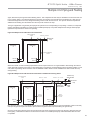
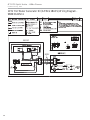
Multiple Units with Internal Flow Controllers
The simplest multiple unit system is one with two (or more)
units utilizing internal Flow Controllers with no external
pumps or flushing valves. In this case the units are piped
in parallel and use the internal flushing valves to flush the
system. The variable speed pump includes an internal check
valve to prevent back (short circuiting) flow through the units.
In this case, flush the loop through the internal flushing
valves in the unit farthest from the loop first. Once the loop is
flushed, then change the internal flushing valves to flush the
heat pump. Next, move the flushing cart to the next closest
unit to the loop.
G T- P C S S p l i t U n i t s - 6 0 H z P u r o n ®
Created: 29 Aug., 2013
Multiple Unit Piping and Flushing
Again, flush the loop through the internal flushing valves. This is important as there may be air/debris in the lines from this unit
to the common piping. Once flushing begins the air will be move into the loop and will need to be flushed out. After the loop
is flushed through the second unit, change the flushing valves to flush the second unit. This process should be repeated for
additional units working from the farthest from the loop to the closest to the loop.
This type of application can generally be employed for systems to 12 tons depending on loop design. However, it is important
perform appropriate calculations to confirm that the variable speed pump can provide adequate flow through all heat pumps
against the loop head when all units are operating.
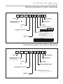
Figure 9a: Multiple Units with Internal Flow Controllers
Size for Heat Pump
‘A’ Flow
Size for ‘A’ + ‘B’ Flow
To Ground
Loop
Heat Pump
A
Heat Pump
B
Size for Heat Pump
‘B’ Flow
Water Out
Water Out
Water In
Water In
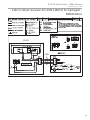
When the number of units or flushing requirements reaches a point where it is no longer feasible to flush through the internal
valves (generally systems of more than 12 tons depending on loop design), external flushing valves should be installed. In this
case, three-way flushing valves should be used or additional isolation valves must be installed to be able to isolate the loop
during flushing.
Figure 9b: Multiple Units with Internal Flow Controllers and External Flushing Valves
Size for Heat Pump
‘A’ Flow
Size for ‘A’ + ‘B’ Flow
Size for ‘A’ + ‘B’ + ‘C’ Flow
Ground Loop
Shut-Off Valve
To Ground
Loop
Heat Pump
A
Heat Pump
B
Heat Pump
C
Indoor Loop
Shut-Off Valve
Flush
Valve
Size for
Heat Pump
‘C’ Flow
Size for
Heat Pump
‘B’ Flow
Water Out
Water Out
Water Out
Water In
Water In
Water In
First, flush the ground loop. The installer should close the indoor loop shut-off valve (or the internal flushing valves in all units)
and open the ground loop shut-off valve to prevent flow through the indoor loop while flushing the ground loop.
Once the ground loop is flushed, close the ground loop shut-off valve and open the indoor loop valve(s) to flush the units and
indoor piping. Remember that there is an internal check valve in the variable speed pump and that backward flow the unit is
not possible.
15
G T- P C S S p l i t U n i t s - 6 0 H z P u r o n ®
Created: 29 Aug., 2013
Multiple Unit Piping and Flushing - Indoor Split (50YGS Only)
Multiple Units with Internal Modulating Valves and
Central Pump
This is an application where multiple units are used in
conjunction with a central, variable speed pump. In this case,
units with closed loop modulating valves are used (do not
use open loop modulating valves on a closed loop system).
External flushing valves are required. This application is for
larger systems, including commercial.
Figure 9c: Multiple Units with Internal Modulating Valves and Central Pump
Size for Heat Pump
‘A’ Flow
Size for ‘A’ + ‘B’ Flow
Ground Loop
Shut-Off Valve
Size for ‘A’ + ‘B’ + ‘C’ Flow
To Ground
Loop
Pump
Heat Pump
Heat Pump
Heat Pump
Size for
Heat Pump
‘B’ Flow
Water Out
Water Out
Water In
Water In
Water In
Once the ground loop is flushed, close the ground loop
shut-off valve and open the pump isolation valve to flush
the units and indoor piping. Once the system is flushed
remember to return the modulating valves to their normal
operating position.
16
Size for
Heat Pump
‘C’ Flow
Water Out
Before flushing, the installer should manually open all
modulating valves as detailed in Closed Loop – External
Central Pumping section of this manual. Next, flush the
ground loop. The installer should close a pump isolation
valve and open the ground loop shut-off valve to prevent flow
through the indoor loop while flushing the ground loop.
Pump
Isolation
Valves
Exp
Tank
Flush
Valve
G T- P C S S p l i t U n i t s - 6 0 H z P u r o n ®
Created: 29 Aug., 2013
Ground Loop Heat Pump Applications
Antifreeze Selection - General
In areas where minimum entering loop temperatures drop
below 40°F [4.4°C] or where piping will be routed through
areas subject to freezing, antifreeze is needed. Alcohols
and glycols are commonly used as antifreeze solutions.
Your local representative should be consulted for the
antifreeze best suited to your area. Freeze protection should
be maintained to 15°F [8.5°C] below the lowest expected
entering loop temperature.
Initially calculate the total volume of fluid in the piping
system using Table 4. Then use the percentage by volume
shown in Table 5 for the amount of antifreeze. Antifreeze
concentration should be checked from a well mixed sample
using a hydrometer to measure specific gravity.
Table 4: Fluid Volume
Fluid Volume (gal [liters] per 100’ [30 meters) Pipe)
Pipe
Size
Volume (gal) [liters]
1”
4.1 [15.3]
1.25”
6.4 [23.8]
2.5”
9.2 [34.3]
3/4” IPS SDR11
2.8 [10.4]
1” iPS SDR11
4.5 [16.7]
Copper
Polyethylene
1.25” IPS SDR11
8.0 [29.8]
1.5” IPS SDR11
10.9 [40.7]
2” IPS SDR11
18.0 [67.0]
Unit Heat Exchanger
Typical
1.0 [3.8]
Flush Cart Tank
10” Dia x 3ft tall
[254mm x 91.4cm tall]
10 [37.9]
WARNING!
WARNING! Always dilute alcohols with water (at least 50%
solution) before using. Alcohol fumes are flammable and
can cause serious injury or death if not handled properly.
When handling methanol (or any alcohol), always wear
eye protection and rubber gloves as alcohols are easily
absorbed through the skin.
Table 5: Antifreeze Percentages by Volume
Type
Methanol
Propylene Glycol
Ethanol*
Minimum Temperature
for Low Temperature Protection
10°F
[-12.2°C]
15°F
[-9.4°C]
20°F
[-6.7°C]
25°F
[-3.9°C]
21%
29%
23%
17%
24%
20%
13%
18%
16%
8%
12%
11%
* Must not be denatured with any petroleum based product
WARNING!
WARNING! Always use properly marked vehicles (D.O.T.
placards), and clean/suitable/properly identified containers
for handling flammable antifreeze mixtures. Post and
advise those on the jobsite of chemical use and potential
dangers of handling and storage.
NOTICE: DO NOT use automotive windshield washer fluid
as antifreeze. Washer fluid contains chemicals that will cause
foaming.
CAUTION!
CAUTION! Always obtain MSDS safety sheets for all
chemicals used in ground loop applications including
chemicals used as antifreeze.
Antifreeze Charging
It is highly recommended to utilize premixed antifreeze fluid
where possible to alleviate many installation problems and
extra labor.
The following procedure is based upon pure antifreeze and
can be implemented during the Full Flush procedure with three
way valves in the Figure 8d - Valve Position C. If a premixed
mixture of 15°F [-9.4°C] freeze protection is used, the system
can be filled and flushed with the premix directly to prevent
handling pure antifreeze during the installation.
1) Flush loop until all air has been purged from system and
pressurize to check for leaks before adding
any antifreeze.
2) Run discharge line to a drain and hook up antifreeze
drum to suction side of pump (if not adding below
water level through approved container). Drain flush cart
reservoir down to pump suction inlet so reservoir can
accept the volume of antifreeze to be added.
3) Calculate the amount of antifreeze required by first
calculating the total fluid volume of the loop from Table 4.
Then calculate the amount of antifreeze needed using Table
5 for the appropriate freeze protection level. Many southern
applications require freeze protection because of exposed
piping to ambient conditions.
4) Isolate unit and prepare to flush only through loop (see
Figure 8a). Start flush cart, and gradually introduce the
required amount of liquid to the flush cart tank (always
introduce alcohols under water or use suction of pump
to draw in directly to prevent fuming) until attaining the
proper antifreeze protection. The rise in flush reservoir
level indicates amount of antifreeze added (some carts
are marked with measurements in gallons or liters). A
ten inch [25.4 cm] diameter cylinder, 3 foot [91.4 cm] tall
holds approximately 8 gallons [30.3 liters] of fluid plus the
hoses (approx. 2 gallons, [7.6 liters], which equals about
10 gallons [37.9 liters] total. If more than one tankful is
required, the tank should be drained immediately by
opening the waste valve of the flush cart noting the
17
G T- P C S S p l i t U n i t s - 6 0 H z P u r o n ®
Created: 29 Aug., 2013
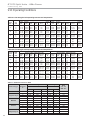
Ground Loop Heat Pump Applications
Chart 1a: Methanol Specific Gravity
Specific Gravity
1.000
0.995
0.990
0.985
0.980
0.975
0.970
0.965
0.960
-50°F -40°F -30°F -20°F -10°F 0°F
10°F 20°F 30°F 40°F 50°F
-45.6°C
-34.4°C
-23.3°C
-12.2°C
-1.1°C
10°C
-40°C
-28.9°C
-17.8°C
-6.7°C
4.4°C
Low Temperature Protection
Chart 1b: Propylene Glycol Specific Gravity
1.07
Specific Gravity
color of the discharge fluid. Adding food coloring to the
antifreeze can help indicate where the antifreeze is in the
circuit and prevents the dumping of antifreeze out the
waste port. Repeat if necessary.
5) Be careful when handling methanol (or any alcohol).
Always wear eye protection and rubber gloves. The
fumes are flammable, and care should be taken with all
flammable liquids. Open flush valves to flush through
both the unit and the loop and flush until fluid is
homogenous and mixed. It is recommended to run the
unit in the heating and cooling mode for 15-20 minutes
each to ‘temper’ the fluid temperature and prepare it for
pressurization. Devoting this time to clean up can be
useful. This procedure helps prevent the periodic “flat”
loop condition.
6) Close the flush cart return valve; and immediately
thereafter, close the flush cart supply valve, leaving a
positive pressure in the loop of approximately 50 psi [345
kPa]. This is a good time to pressure check the system
as well. Check the freeze protection of the fluid with the
proper hydrometer to ensure that the correct amount of
antifreeze has been added to the system. The hydrometer
can be dropped into the flush reservoir and the reading
compared to Chart 1a for Methanol, 1b for Propylene
Glycol, and 1c for Ethanol to indicate the level of freeze
protection. Do not antifreeze more than a +10°F [-12.2°C]
freeze point. Specific gravity hydrometers are available
in the residential price list. Repeat after reopening and
flushing for a minute to ensure good second sample
of fluid. Inadequate antifreeze protection can cause
nuisance low temperature lockouts during cold weather.
7) Close the flush cart return valve; immediately thereafter,
close the flush cart supply valve, shut off the flush cart
leaving a positive pressure in the loop of approximately
1.06
1.05
1.04
1.03
1.02
1.01
1.00
-40°F
-40°C
-30°F
-20°F
-10°F
0°F
10°F
20°F
-34.4°C -28.9°C -23.3°C -17.8°C -12.2°C -6.7°C
30°F
40°F
-1.1°C
4.4°C
Low Temperature Protection
Chart 1c: Ethanol Specific Gravity
1.000
0.995
0.990
0.985
WARNING!
0.980
WARNING! Always dilute alcohols with water (at least 50%
solution) before using. Alcohol fumes are flammable and
can cause serious injury or death if not handled properly.
-5°F
0°F
5°F
10°F
15°F
20°F
25°F
30°F
35°F
-20.6°C
-17.8°C
-15.0°C
-12.2°C
-9.4°C
-6.7°C
-3.9°C
-1.1°C
1.7°C
Low Temperature Protection
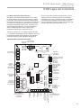
Figure 10: Low Temperature Cutout Selection
Off
JW3
Off
Off
On
1 2 3 4 5 6 7 8
c1
ay
On
1 2 3 4 5 6 7 8
S3
50-75 psi [345-517 kPa]. Refer to Figure 8e for more
details.
1 24Vdc
S2
A0-1 A0-2
EH1
4 EH2
Comp
Relay
P6
CCG
c2
ay
P11
AO2 Gnd
P10
T1 T2 T2 T3 T3 T4 T4
P9
CC
T5 T5 T6 T6
DXM2 PCB
JW3-LT1 jumper should be clipped
for low temperature operation
18
P7
RV
Relay
CCH
Relay
S1
Low Water Temperature Cutout Setting - DXM2 Control
When antifreeze is selected, the LT1 jumper (JW3) should
be clipped to select the low temperature (antifreeze 10°F
[-12.2°C]) set point and avoid nuisance faults (see “Low
Water Temperature Cutout Selection” in this manual).
LT2
LT2
RV
RV
CO
12 CO
On
1 2 3 4
When handling methanol (or any alcohol), always wear
eye protection and rubber gloves as alcohols are easily
absorbed through the skin.
0.975
G T- P C S S p l i t U n i t s - 6 0 H z P u r o n ®
Created: 29 Aug., 2013
Closed Loop - External Central Pumping Applications
(Indoor Split 50YGS Only)
Figure 11: Typical Closed Loop with Central Pumping Application (with Internal Modulating Motorized Valve Shown)
To Thermostat
High and Low
Voltage Knockouts
Internal
Motorized
Modulating
Valve
Water Out
Water In
Vibration Isolation Pad
GT-PCS Indoor Digital units are available with a modulating
water valve option for closed-loop applications with external
central pumping (designated by a 5 in the 9th position of the
unit model number). With this option, the Modulating Valve
is regulated by the Communicating DXM2 board based on
entering and leaving water temperature (ΔT). The DXM2
board outputs a 0-10v signal to determine valve position
(flow rate). The modulating valve defaults to closed position
if it loses signal but still has 24V power running to it. If the
motorized modulating valve loses both signal from the DXM2
board AND 24V power, it will remain in the same position it
was in when it lost 24V power.
Note: The Cv (flow coefficient) of the valve used in these
units is DIFFERENT that the Cv of the valve used in the
open loop unit. It is not advisable for use in open loop
applications as sound/noise issues may result. Units with
the water circuit for closed loop, central pumping option are
only available with a copper water coil.
while turning the handle to the open position as shown in
Figure 12. This fully opens the valve for flushing. Once
flushing is complete, press the lock release again and return
the valve handle to its normally closed position.
Figure 12: Internal Modulating Motorized Valve Positions
Sizes 026-049
Size 064
Closed
Closed
Open
Open
/RFN5HOHDVH
To manually open the internal modulating motorized water
valve in 50YGS026 – 049 push down on the handle to unlock
it. Then rotate the handle to the open position as shown
in Figure 12. This fully opens the valve for flushing. Once
flushing is complete, return the valve handle to its normally
closed position.
To manually open the internal modulating motorized water
valve in 50YGS064, push down on the lock release button
19
G T- P C S S p l i t U n i t s - 6 0 H z P u r o n ®
Created: 29 Aug., 2013
Open Loop or Ground-Water Heat Pump Applications
Once flushing is complete, press the lock release again and
return the valve handle to its normally closed position.
Figure 13: Typical Open Loop/Well Application
To Thermostat
High and Low
Voltage Knockouts
Internal Motorized
Modulating Valve
Pressure
Tank
Water Out
Water In
Boiler
Drains
Shut Off
Ball Valves
for Isolation
Optional
Filter
Vibration Isolation Pad
CAUTION!
CAUTION! Refrigerant pressure activated water regulating
valves should never be used with this equipment.
GT-PCS Digital Indoor Split (50YGS) units are available with
a water circuit option for open loop applications (designated
by a 6 in the 9th position of the unit model number).
The Motorized Modulating Valve is regulated by the
Communicating DXM2 board based on entering and leaving
water temperature (ΔT). The DXM2 board gives a 0-10v
signal to determine flow rate. The motorized modulating
valve defaults to closed position if it loses signal but still
has 24V power running to it. If the motorized modulating
valve loses both signal from the DXM2 board AND 24V
power, it will remain in the same position it was in when it
lost 24V power. DO NOT USE open loop units in closed loop
applications due to significant pressure drop through the
open loop motorized modulating valve. This option is only
available with Cupro-Nickel Water Coil.
To manually open the internal modulating motorized water
valve in 50YGS026 – 049 push down on the handle to unlock
it. Then rotate the handle to the open position as shown
in Figure 12. This fully opens the valve for flushing. Once
flushing is complete, return the valve handle to its normally
closed position.
To manually open the internal modulating motorized water
valve in 50YGS064 – 072, push down on the lock release
button while turning the handle to the open position as
shown in Figure 12. This fully opens the valve for flushing.
20
Open Loop - Ground Water Systems
Typical open loop piping is shown in Figure 13. Shut off valves
should be included for ease of servicing. Boiler drains or other
valves should be “tee’d” into the lines to allow acid flushing
of the heat exchanger. Shut off valves should be positioned
to allow flow through the coax via the boiler drains without
allowing flow into the piping system. Schrader ports built into
unit may be used to measure heat exchanger pressure drop.
Water temperature can be viewed on the communicating
thermostat. Piping materials should be limited to copper, PE,
or PVC SCH80. Note: Due to the pressure and temperature
extremes, PVC SCH40 is not recommended.
Water quantity should be plentiful and of good quality. Consult
Table 6 for water quality requirements. Integrated VariableSpeed Water Flow Control units for open loop applications
always come with Cupro-Nickel coils. In ground water
situations where scaling could be heavy or where biological
growth such as iron bacteria will be present, an open loop
system is not recommended. Heat exchanger coils may
over time lose heat exchange capabilities due to build up of
mineral deposits. Heat exchangers must only be serviced by a
qualified technician, as acid and special pumping equipment
is required. Desuperheater coils can likewise become scaled
and possibly plugged. In areas with extremely hard water,
the owner should be informed that the heat exchanger
may require occasional acid flushing. In some cases, the
desuperheater option should not be recommended due to
hard water conditions and additional maintenance required.
Water Quality Standards
Table 6 must be consulted for water quality requirements.
Scaling potential should be assessed using the pH/Calcium
hardness method. If the pH <7.5 and the Calcium hardness
is less than 100 ppm, scaling potential is low. If this method
yields numbers out of range of those listed, a monitoring plan
should be implemented in these probable scaling situations.
Other water quality issues such as iron fouling, corrosion
prevention and erosion and clogging should be referenced in
Table 6.
Pressure Tank and Pump
Use a closed, bladder-type pressure tank to minimize
mineral formation due to air exposure. The pressure tank
should be sized to provide at least one minute continuous
run time of the pump using its drawdown capacity rating to
prevent pump short cycling. Discharge water from the unit
is not contaminated in any manner and can be disposed
of in various ways, depending on local building codes (e.g.
recharge well, storm sewer, drain field, adjacent stream
or pond, etc.). Most local codes forbid the use of sanitary
sewer for disposal. Consult your local building and zoning
department to assure compliance in your area.
G T- P C S S p l i t U n i t s - 6 0 H z P u r o n ®
Created: 29 Aug., 2013
Open Loop or Ground-Water Heat Pump Applications
The pump should be sized to handle the home’s domestic
water load (typically 5-9 gpm [23-41 l/m]) plus the flow rate
required for the heat pump. Pump sizing and expansion
tank must be chosen as complimentary items. For example,
an expansion tank that is too small can cause premature
pump failure due to short cycling. Variable speed pumping
applications should be considered for the inherent energy
savings and smaller pressure tank requirements.
Water Coil Low Temperature Limit Setting
For all open loop systems the 30°F [-1.1°C] LT1 setting
(factory setting-water) should be used to avoid freeze
damage to the unit. See “Low Water Temperature Cutout
Selection” (Figure 10) in this manual for details on the low
limit setting.
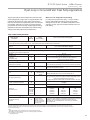
Table 6: Water Quality Standards
Water Quality
Parameter
HX
Material
Closed
Recirculating
Open Loop and Recirculating Well
Scaling Potential - Primary Measurement
Above the given limits, scaling is likely to occur. Scaling indexes should be calculated using the limits below
pH/Calcium Hardness
Method
All
-
pH < 7.5 and Ca Hardness <100ppm
Index Limits for Probable Scaling Situations - (Operation outside these limits is not recommended)
Scaling indexes should be calculated at 66°C for direct use and HWG applications, and at 32°C for indirect HX use.
A monitoring plan should be implemented.
Ryznar
6.0 - 7.5
All
Stability Index
If >7.5 minimize steel pipe use.
-0.5 to +0.5
Langelier
All
If <-0.5 minimize steel pipe use. Based upon 66°C HWG and
Saturation Index
Direct well, 29°C Indirect Well HX
Iron Fouling
Iron Fe 2+ (Ferrous)
(Bacterial Iron potential)
All
Iron Fouling
All
-
<0.2 ppm (Ferrous)
If Fe2+ (ferrous)>0.2 ppm with pH 6 - 8, O2<5 ppm check for iron bacteria.
-
<0.5 ppm of Oxygen
Above this level deposition will occur .
Corrosion Prevention
6 - 8.5
pH
All
Hydrogen Sulfide (H2S)
All
Ammonia ion as hydroxide, chloride,
nitrate and sulfate compounds
All
Monitor/treat as
needed
-
6 - 8.5
Minimize steel pipe below 7 and no open tanks with pH <8
<0.5 ppm
At H2S>0.2 ppm, avoid use of copper and copper nickel piping or HX's.
Rotten egg smell appears at 0.5 ppm level.
Copper alloy (bronze or brass) cast components are OK to <0.5 ppm.
-
<0.5 ppm
Maximum Allowable at maximum water temperature.
Maximum
Chloride Levels
Copper
Cupronickel
304 SS
316 SS
Titanium
-
10$C
<20ppm
<150 ppm
<400 ppm
<1000 ppm
>1000 ppm
24$C
NR
NR
<250 ppm
<550 ppm
>550 ppm
38 C
NR
NR
<150 ppm
< 375 ppm
>375 ppm
Erosion and Clogging
Particulate Size and
Erosion
All
<10 ppm of particles
and a maximum
velocity of 1.8 m/s
Filtered for maximum
841 micron [0.84 mm,
20 mesh] size.
<10 ppm (<1 ppm "sandfree” for reinjection) of particles and a maximum
velocity of 1.8 m/s. Filtered for maximum 841 micron 0.84 mm,
20 mesh] size. Any particulate that is not removed can potentially
clog components.
The
Quality Table
provides
quality requirements
for heat
ClimateMaster
coaxial
heat
exchangers.
water properties
are outside of an
those
ThisClimateMaster
Water Quality Water
Table provides
water
quality water
requirements
for the coaxial
exchangers.
When
water
propertiesWhen
are outside
of these requirements,
requirements,
an external
secondary heat
be the
usedheat
to isolate
pump heat
exchanger
from the
unsuitable
water.
to dothe
so will
void the
external secondary
heat exchanger
mustexchanger
be used tomust
isolate
pump the
heatheat
exchanger
from
the unsuitable
water.
Failure
to do Failure
so will void
warranty
for
the coaxial
exchanger.
warranty
forheat
the coaxial
heat exchanger.
Rev.: 3/22/2012
Notes:
&ORVHG5HFLUFXODWLQJV\VWHPLVLGHQWLILHGE\Dclosed pressurized piping system.
5HFLUFXODWLQJRSHQZHOOVVKRXOGREVHUYHWKHRSHQUHFLUFXODWLQJGHVLJQFRQVLGHUDWLRQV
15Application not recommended.
1RGHVLJQ0D[LPXP
21
G T- P C S S p l i t U n i t s - 6 0 H z P u r o n ®
Created: 29 Aug., 2013
Refrigeration Installation
CAUTION!
CAUTION! Puron® systems operate at higher pressures
than R-22 systems. Be certain that service equipment
(gauges, tools, etc.) is rated for Puron®. Some R-22
service equipment may not be acceptable.
CAUTION!
CAUTION! Installation of a factory supplied liquid line
bi-directional filter drier is required. Never install a suction
line filter in the liquid line.
Line Set Installation
Figures 4a and 4b illustrate typical installations of a compressor
section matched to either an air handler (fan coil) or add-on
furnace coil. Table 7 shows typical line-set diameters at various
lengths. Lineset lengths should be kept to a minimum and
should always be installed with care to avoid kinking. Line sets
over 60 feet [18 meters] long are not recommended due to
potential oil transport problems and excessive pressure drop. If
the line set is kinked or distorted, and it cannot be formed back
into its original shape, the damaged portion of the line should
be replaced. A restricted line set will effect the performance of
the system.
Split units are shipped with a filter drier (loose) inside the
cabinet that must be installed in the liquid line at the line set.
All brazing should be performed using nitrogen circulating
at 2-3 psi [13.8-20.7 kPa] to prevent oxidation inside the
tubing. All linesets should be insulated with a minimum of
1/2” [13mm] thick closed cell insulation. Liquid lines should
be insulated for sound control purposes. All insulation
tubing should be sealed using a UV resistant paint or
covering to prevent deterioration from sunlight.
When passing refrigerant lines through a wall, seal
opening with silicon-based caulk. Avoid direct contact
with water pipes, duct work, floor joists, wall studs,
floors or other structural components that could transmit
compressor vibration. Do not suspend refrigerant tubing
from joists with rigid straps. Do not attach line set to the
wall. When necessary, use hanger straps with isolation
sleeves to minimize transmission of line set vibration to
the structure.
Installing the Lineset at the Compressor Section
Braze the line set to the service valve stubs as shown in Figure
14. Remove the schraeder cores and heat trap the valves to
avoid overheating and damage. On installations with long line
sets, copper adapters may be needed to connect the larger
diameter tube to the stubs. Nitrogen should be circulated
through the system at 2-3 psi [13.8-20.7 kPa] to prevent
oxidation contamination. Use a low silver phos-copper braze
alloy on all brazed connections. Compressor section is
shipped with a factory charge. Therefore, service valves
should not be opened until the line set has been leak
tested, purged and evacuated. See “Charging the System.”
Installing the Indoor Coil and Lineset
Figure 15 shows the installation of the lineset and TXV to a
typical indoor coil. An indoor coil or air handler (fan coil) with a
TXV is required. Coils with cap tubes may not be used. If coil
includes removable fixed orifice, the orifice must be removed
and a TXV must be installed as shown in Figure 15. Fasten
the copper line set to the coil. Nitrogen should be circulated
through the system at 2-3 psi [13.8-20.7 kPa] to prevent
oxidation inside the refrigerant tubing. Use a low silver phoscopper braze alloy on all brazed connections.
Table 7: Lineset Diameters and Charge Information
Factory†
Charge (oz)
[kg]
Basic*
Charge (oz)
[kg]
20 Feet [6 meters]
40 Feet [12 meters]
60 Feet [18 meters]
Liquid
Liquid
Liquid
026
93 [2.64]
78 [2.21]
3/8"
3/4"
3/8"
3/4"
3/8"
3/4"
038
120 [3.40]
105 [2.98]
3/8"
7/8"
3/8"
7/8"
3/8"
7/8"
049
137 [3.88]
122 [3.46]
3/8"
7/8"
3/8"
7/8"
3/8"
7/8"
064
212 [6.01]
182 [5.16]
1/2"
7/8"
1/2"
7/8"
1/2"
7/8"
Model
Suction
Suction
Suction
GT-PCS Series
TES/TEP
Series
• Basic charge includes only the amount required for the condensing unit and the evaporating coil.
An additional amount should be added allowing 0.6oz per ft. for 3/8” [0.6g per cm] and 1.2oz per ft. for 1/2” [1.1g per cm] of lineset used.
†Factory charge is preset for 25’ [7.6 meters] lineset.
22
G T- P C S S p l i t U n i t s - 6 0 H z P u r o n ®
Created: 29 Aug., 2013
Refrigeration Installation
Figure 14: Braze Instructions
Figure 15: Air Coil Connection
Fully Insulated
Vapor Line
Suction
Bulb (Must be
Installed and
Insulated)
Equalizer
Line
TXV (‘IN’ toward
compressor section)
LT2
Sensor
Suction Line
Fully Insulated
Liquid Line
TXV has internal
check valve
Liquid Line
Nitrogen Braze
WARNING!
)XOO\,QVXODWHG
/LTXLG/LQH
)XOO\,QVXODWHG
9DSRU/LQH
Table 8: Service Valve Positions
Position
Description
Operation Position
CCW - Full Out
CCW - Full Out 1/2 turn CW Service Position
CCW - Full In
Shipping Position
System
Service
Port
Open
Open
Closed
Closed
Open
Open
Re-Using Existing Line Set - R-22 to Puron® Conversion
New line sets are always recommended, but are required if;
• The previous system had a compressor burn out.
• The existing line set has oil traps.
• The existing line set is larger or smaller than the
recommended line set for the Puron® system.
• The existing line set is damaged, corroded, or shows signs
of abrasion/fatigue
WARNING! If at all possible, it is recommended that a
new line set be used when replacing an existing R-22
system with an Puron® system. In rare instances where
replacing the line set is not possible, the line set must be
flushed prior to installation of the Puron® system. It is
also important to empty all existing traps.
Polyolester (POE) oils are used in units charged with
Puron® refrigerant. Residual mineral oil can act as an
insulator on the wall of the coil tubing, hindering proper
heat transfer and thus reducing system efficiency and
capacity. Another important reason to thoroughly flush
the line set is remove any trash and other contaminants
that may be present which could clog the thermal
expansion valve.
Failure to properly flush the system per the instructions
below will void the warranty.
WARNING!
WARNING! The Environmental Protection Agency
prohibits the intentional venting of HCFC and HFC
refrigerants during maintenance, service, repair and
disposal of appliance. Approved methods of recovery,
recycling or reclaiming must be followed.
CAUTION!
CAUTION! This procedure should not be performed
on systems which contain containments (Example:
compressor burn out).
Required Equipment
The following equipment will be required in order to flush the
indoor coil and existing line set:
• Two R-22 recovery cylinders
• Refrigerant recovery machine with a pump down feature
• Two sets of gauges (one used for R-22 and one used with
the Puron®).
• Cylinder of clean R-22 (minimum amount required to
adequately flush shown below)
23
G T- P C S S p l i t U n i t s - 6 0 H z P u r o n ®
Created: 29 Aug., 2013
Refrigeration Installation
°
°
°
3/4” Diameter suction lines: 1/4 lb. per foot of line set +
1 lb. per ton for indoor coil.
7/8” diameter suction lines: 1/3 lb. per foot of line set +
1 lb. per ton for indoor coil
1-1/8” diameter suction lines: 1/2 lb. per foot of line set
+ 1 lb. per ton for indoor coil.
Example: 3-ton system with 40 ft. long line set and 3/4”
suction line.
Line set: 1/4 lb./ft. x 40 ft. = 10 lb.
Indoor coil: 1 lb./ton x 3 tons = 3 lbs. (not required if coil
is removed and lines are connected together)
Total: 10 lbs. + 3 lbs. = 13 lbs. to adequately flush line
set and indoor coil.
The Flushing Procedure
1. Remove the existing R-22 refrigerant by selecting the
appropriate procedure stated below.
If the unit is not operational, follow steps A-E.
• A.) First, disconnect all power supply to the existing
outdoor unit.
• B.) Connect a clean refrigerant recovery cylinder and
the refrigerant recovery machine to the existing unit
according to the instructions provided with the recovery
machine.
• C.) Remove all R-22 refrigerant from the existing system.
• D.) Check the gauges after shutdown to confirm all
refrigerant has been completely removed from the entire
system.
• E.) Disconnect the liquid and vapor lines from the
existing outdoor unit.
24
2.
3.
4.
5.
6.
If the unit is operational, follow steps F- L.
• F.) First, start the existing R-22 system in the cooling
mode and close the liquid line valve.
• G.) Completely pump all existing R-22 refrigerant into
the outdoor unit. It will be necessary to bypass the low
pressure switch if the unit is so equipped to ensure that
the refrigerant is completely evacuated.)
• H.) The low side system pressures will eventually reach 0
psig. When this happens, close the vapor line valve and
immediately shut the outdoor unit off.
• I.) Check the gauges after shutdown to confirm that the
valves are not allowing refrigerant to leak back into the
low side of the system.
• J.) Disconnect power to the indoor furnace or airhandler to kill low voltage to the outdoor unit.
• K.) Disconnect the power supply wiring from the
existing outdoor unit.
• L.) Unsweat the liquid and vapor lines from the existing
outdoor unit.
Remove the existing outdoor unit.
Set the new Puron® unit in place and braze the liquid
and vapor lines to the unit connections. Connect the low
voltage and line voltage to the new outdoor unit. Do not
turn on power supply to the unit and do not open the
outdoor unit service valves at this time.
The indoor coil can be left in place for the flushing process
or removed.
If the indoor coil is removed, the suction and liquid line
must be connected together on the indoor coil end. See
illustration for recommended method for connecting these
together.
If the indoor coil is left in place during flushing, removing
G T- P C S S p l i t U n i t s - 6 0 H z P u r o n ®
Created: 29 Aug., 2013
Refrigeration Installation
7.
8.
9.
10.
11.
12.
13.
14.
the existing refrigerant flow control orifice or thermal
expansion valve prior to flushing is highly recommended
to assure proper flushing. Use a field-provided fitting or
piece of copper tubing to reconnect the lines where the
thermal expansion valve was removed.
Remove the pressure tap valve cores from the outdoor
unit’s service valves.
Connect an R-22 cylinder of clean R-22 refrigerant to the
vapor service valve. (see “Required Equipment Section”
for minimum required amount of R-22 for adequate
flushing)
Connect the low pressure side of an R-22 gauge set to the
liquid line valve.
Connect a hose from the recovery machine with an empty
recovery drum to the common port of the gauge set.
Set the recovery machine for liquid recovery and start the
machine.
Open the gauge set low side valve. This will allow the
recovery machine to pull a vacuum on the existing system
line set.
Make sure to invert the cylinder of clean R-22 refrigerant
and open the cylinder’s valve to allow liquid refrigerant to
flow into the system through the vapor line valve. (This
should allow the refrigerant to flow from the cylinder and
through the line set before it enters the recovery machine.)
The cylinder should not be inverted if it is the type with
separate liquid and vapor valves. Use the liquid valve on
the cylinder in this case, keeping the cylinder upright.
Once the liquid refrigerant has been completely recovered,
switch the recovery machine to vapor recovery so that the
R-22 vapor can be completely recovered.
IMPORTANT! Always remember, every time the
system is flushed you must always pull a vacuum
with a recovery machine on the system at the
end of each procedure. (If desired, a second flushing
with clean refrigerant may be performed if insufficient
amounts of mineral oil were removed during the initial
flush.)
15. Tightly close the valve on the inverted R-22 cylinder and
the gauge set valves.
16. Completely pump all remaining R22 refrigerant out of the
recovery machine and turn the machine off.
17. Before removing the recovery machine, R-22 refrigerant
cylinder and gauges, break the vacuum on the refrigerant
lines and indoor coil using dry-nitrogen.
18. Unsweat the liquid and vapor lines from the old indoor
coil or from each other and install a new matched Puron®
indoor coil, connecting the flushed refrigerant lines to the
new coil using field supplied connectors and tubing.
19. Reinstall pressure tap valve cores into unit service valves.
20. Pressurize the lines and coil and check for leaks in the line
set connection points using a soap solution.
21. Thoroughly evacuate the line set and indoor coil per the
instructions found in this manual.
22. Open the liquid and vapor service valves, releasing the
Puron® refrigerant contained in the outdoor unit into the
evacuated line set and indoor coil.
23. Energize the system and adjust the refrigerant charge
according to the charging procedures found in this
manual.
25
G T- P C S S p l i t U n i t s - 6 0 H z P u r o n ®
Created: 29 Aug., 2013
Refrigeration Installation
FP2 Sensor Installation
An FP2 sensor with violet wiring is shipped loose with the
compressor section. This is the air coil low temperature
protection sensor. Install this sensor on the refrigerant line
between the indoor expansion valve and the air coil using
thermal compound and the supplied mounting clips. Ensure
that the sensor makes good thermal contact with the refrigerant
line and insulate the sensor.
Air coil low temperature protection will not be active if this
sensor is installed incorrectly or is not installed.
Add-On Heat Pump Applications
The indoor coil should be located in the supply side of
the furnace to avoid condensation damage to the furnace
heat exchanger for add-on heat pump applications. A high
temperature limit switch should be installed as shown in
Figure 16b just upstream of the coil to de-energize the
compressor any time the furnace is energized to avoid
blowing hot air directly into the coil, elevating refrigerant
pressures during operation. The heat pump will trip out on
high pressure lockout without some method of disengaging
the compressor during furnace operation. Alternatively, some
thermostats with “dual fuel” mode will automatically deenergize the compressor when second stage (backup) heat
is required.
NOTICE! The air coil should be thoroughly washed with a
filming agent, (dishwasher detergent like Cascade) to help
condensate drainage. Apply a 20 to 1 solution of detergent
and water. Spray both sides of coil, repeat and rinse
thoroughly with water.
PARTIAL CHARGE METHOD - Open service valve fully
counterclockwise and then turn back in one-half turn to
open service port. Add vaporized (Gas) into the suction side
of the compressor until the pressure in the system reaches
approximately 100-120 psig. Never add liquid refrigerant into
the suction side of a compressor. Start the unit in heating
and add gas to the suction port at a rate not to exceed
five pounds [2.27 kg] per minute. Keep adding refrigerant
until the complete charge has been entered. Superheat is
measured using suction temperature and pressure at the
compressor suction line. Subcooling should be measured
using the liquid line temperature immediately outside the
compressor section cabinet and either the liquid line service
valve pressure or the compressor discharge pressure. Note
that different values from tables 16a-16d will be obtained
due to the pressure losses through the condenser heat
exchanger. Adding refrigerant will increase sub-cooling
while superheat should remain fairly constant allowing for
a slight amount of hunting in TXV systems. This increase in
subcooling will require 5 minutes or so of operation before it
should be measured. After values are measured, compare to
the chart and go to “FINAL EVALUATION.”
Evacuation and Charging the Unit
LEAK TESTING - The refrigeration line set must be pressurized
and checked for leaks before evacuating and charging the unit.
To pressurize the line set, attach refrigerant gauges to the service
ports and add an inert gas (nitrogen or dry carbon dioxide) until
pressure reaches 60-90 psig [413-620 kPa]. Never use oxygen or
acetylene to pressure test. Use a halogen leak tester or a good
quality bubble solution to detect leaks on all connections made
in the field. Check the service valve ports and stem for leaks. If
a leak is found, repair it and repeat the above steps. For safety
reasons do not pressurize system above 150 psig [1034 kPa].
System is now ready for evacuation and charging.
FINAL EVALUATION -In a split system, cooling subcooling
values can be misleading depending on the location of the
measurement. Therefore, it is recommended that charging
be monitored in the heating mode. Charge should be
evaluated by monitoring the subcooling in the heating mode.
After initial check of heating sub-cooling, shut off unit and
allow to sit 3-5 minutes until pressures equalize. Restart
unit in the cooling mode and check the cooling superheat
against Tables 16a-16d. If unit runs satisfactorily, charging
is complete. If unit does not perform to specifications the
cooling TXV (air coil side) may need to be readjusted (if
possible) until the cooling superheat values are met.
Turn service valves full out CCW (see Table 8) and then turn
back in one-half turn to open service ports. Add the required
refrigerant so that the total charge calculated for the unit and
Checking Superheat and Subcooling
The TXV should be brazed into place as shown in Figure 15,
keeping the “IN” side toward the compressor section. The
TXV has an internal check valve and must be installed in the
proper direction for operation. Always keep the valve body
cool with a brazing shield and wet rags to prevent damage
to the TXV. Attach the bulb to the suction line using the
supplied hose clamp. Be careful not to overtighten the clamp
and deform the bulb.
26
line set is now in the system. Open the service valve fully
counter clockwise so that the stem will backseat and prevent
leakage through the schrader port while it is not in use.
Start unit in the heating mode and measure superheat and
subcooling values after 5 minutes of run time. See tables
16a-16d for superheat and sub-cooling values. Superheat
is measured using suction temperature and pressure at the
compressor suction line. Subcooling should be measured
using the liquid line temperature immediately outside the
compressor section cabinet and either the liquid line service
valve pressure or the compressor discharge pressure. Note
that different values from tables 16a-16d will be obtained
due to the pressure losses through the condenser heat
exchanger. Adding refrigerant will increase sub-cooling
while superheat should remain fairly constant allowing for
a slight amount of hunting in TXV systems. This increase in
subcooling will require 5 minutes or so of operation before it
should be measured. After values are measured, compare to
the chart and go to “FINAL EVALUATION.”
G T- P C S S p l i t U n i t s - 6 0 H z P u r o n ®
Created: 29 Aug., 2013
Refrigeration Installation
Figure 16a: Typical Split/Air Handler Installation
Power
Disconnects
TXV 'IN' toward
Compressor
Section
Insulated
Linesets
PVC Condensate
with vented trap
Compressor Section
Low
Voltage
Air pad or Extruded
polystryene
Figure 16b: Typical Split/Add-on Coil Fossil Fuel Furnace Installation
TXV
TXV 'IN'
'IN' toward
Compressor
Compressor
Section
Section
Air Temperature
Limit Switch
PVC Condensate
with vented trap
Compressor Section
Air pad or Extruded
polystyrene
27
G T- P C S S p l i t U n i t s - 6 0 H z P u r o n ®
Created: 29 Aug., 2013
Refrigeration Installation
Determining Superheat:
1. Measure the temperature of the suction line at a point
near the expansion valve bulb.
2. Determine the suction pressure by attaching refrigeration
gauges to the suction schrader connection at the
compressor.
3. Convert the pressure obtained in step 2 to saturation
temperature (boiling point) by using the pressure/
temperature conversion table on the gauge set.
4. Subtract the temperature obtained in step 3 from step
1. The difference will be the superheat of the unit or the
total number of degrees above saturation temperature.
Refer to Tables 16a-16d for superheat ranges at specific
entering water conditions.
Evacuation Of The Lineset And Coil
The line set and coil must be evacuated to at least 500
microns to remove any moisture and noncondensables.
Evacuate the system through both service ports in the
shipping position (full CW in - see table 8) to prevent false
readings on the gauge because of pressure drop through
service ports. A vacuum gauge or thermistor capable of
accurately meausuring the vacuum depth is crucial in
determining if the system is ready for charging. If the system
meets the requirements in Figure 17, it is ready for charging.
Figure 17: Evacuation Graph
Example:
The temperature of the suction line at the sensing bulb is
50°F. The suction pressure at the compressor is 110 psig
which is equivalent to 36°F saturation temperature from the
Puron® press/temp conversion table on the gauge set.
36°F subtracted from 50°F = 14°F Superheat.
Determining Sub-Cooling:
1. Measure the temperature of the liquid line on the smaller
refrigerant line (liquid line) just outside of the cabinet.
This location will be adequate for measurement in both
modes unless a significant temperature drop in the liquid
line is anticipated.
2. Determine the condensor pressure (high side) by
attaching refrigerant gauges to the schrader connection
on the liquid line service valve. If the hot gas discharge
line of the compressor is used, refer to the appropriate
column in Tables 16a-16d.
3. Convert the pressure obtained in step 2 to the
saturation temperature by using the press/temp
conversion table on the gauge set.
4. Subtract the temperature of Step 3 from the temperature
of Step 1. The difference will be the sub-cooling value for
that unit (total degrees below the saturation temperature).
Refer to Tables 16a-16d for sub-cooling values at specific
entering water temperatures.
Example:
The condenser pressure at the service port is 335 psig,
which is equivalent to 104°F saturation temperature.
Discharge pressure is 365 psig at the compressor (109°F
saturation temperature). Measured liquid line temperature is
100°F. 100°F subtracted from 104°F = 4 degrees sub-cooling
(9 degrees if using the compressor discharge pressure).
28
NOTICE!
NOTICE: Use tables 16a to 16d for superheat/
subcooling values. These tables use discharge pressure
(converted to saturation temperature) and liquid line
temperature for subcooling calculations. If using liquid
line pressure, subtract 3°F from the table values.
Charging The System
There are two methods of charging a refrigerant system. One
method is the total charge method, where the volume of the
system is determined and the refrigerant is measured and
added into the evacuated system. The other method is the
partial charge method where a small initial charge is added
to an evacuated system, and remaining refrigerant added
during operation.
Total Charge Method - See Table 7 for the compressor
section basic charge. For line sets with 3/8” liquid lines
add 0.6 ounces of refrigerant to the basic charge for every
installed foot of liquid line [0.6 grams per cm]. Add 1.2 oz.
per foot [1.1 grams per cm] if using l/2” line. Once the total
charge is determined, the factory pre-charge (Table 7) is
subtracted and the remainder is the amount needed to be
added to the system. This method should be used with the
AHRI matched air handler.
G T- P C S S p l i t U n i t s - 6 0 H z P u r o n ®
Created: 29 Aug., 2013
Hot Water Generator
The HWG (Hot Water Generator) or desuperheater option
provides considerable operating cost savings by utilizing
excess heat energy from the heat pump to help satisfy
domestic hot water requirements. The HWG is active
throughout the year, providing virtually free hot water when
the heat pump operates in the cooling mode or hot water at
the COP of the heat pump during operation in the heating
mode. Actual HWG water heating capacities are provided in
the appropriate heat pump performance data.
Heat pumps equipped with the HWG option (indoor model
only) include a built-in water to refrigerant heat exchanger
that eliminates the need to tie into the heat pump refrigerant
circuit in the field. The control circuit and pump are also
built in for residential equipment. Figure 18 shows a typical
example of HWG water piping connections on a unit with
built-in circulating pump. This piping layout reduces scaling
potential.
The temperature set point of the HWG is field selectable
on DXM2 to 125°F or 150°F . The 150°F set point allows
more heat storage from the HWG. For example, consider
the amount of heat that can be generated by the HWG when
using the 125°F set point, versus the amount of heat that can
be generated by the HWG when using the 150°F set point.
In a typical 50 gallon two-element electric water heater
the lower element should be turned down to 100°F, or the
lowest setting, to get the most from the HWG. The tank will
eventually stratify so that the lower 80% of the tank, or 40
gallons, becomes 100°F (controlled by the lower element).
The upper 20% of the tank, or 10 gallons, will be maintained
at 125°F (controlled by the upper element).
Using a 125°F set point, the HWG can heat the lower 40
gallons of water from 100°F to 125°F, providing up to 8,330
btu’s of heat. Using the 150°F set point, the HWG can heat
the same 40 gallons of water from 100°F to 150°F and the
remaining 10 gallons of water from 125°F to 150°F, providing
a total of up to 18,743 btu’s of heat, or more than twice as
much heat as when using the 125°F set point.
This example ignored standby losses of the tank. When
those losses are considered the additional savings are even
greater.
Electric water heaters are recommended. If a gas, propane,
or oil water heater is used, a second preheat tank must be
installed (Figure 19). If the electric water heater has only a
single center element, the dual tank system is recommended
to insure a usable entering water temperature for the HWG.
Typically a single tank of at least 52 gallons (235 liters) is
used to limit installation costs and space. However, a dual
tank, as shown in Figure 19, is the most efficient system,
providing the maximum storage and temperate source water
to the HWG.
It is always advisable to use water softening equipment on
domestic water systems to reduce the scaling potential and
lengthen equipment life. In extreme water conditions, it may
be necessary to avoid the use of the HWG option since the
potential cost of frequent maintenance may offset or exceed
any savings. Consult Table 6 for scaling potential tests.
WARNING!
WARNING! A 150°F SETPOINT MAY LEAD TO
SCALDING OR BURNS. THE 150°F SET POINT MUST
ONLY BE USED ON SYSTEMS THAT EMPLOY AN
APPROVED ANTI-SCALD VALVE.
Figure 19: HWG Double Tank Installation
(Indoor Compressor Section)
Hot Outlet to
house
Figure 18: Typical HWG Installation
(Indoor Compressor Section)
Cold Inlet
Cold Inlet from
Domestic supply
Hot Outlet
Hot Outlet
to home
Cold
Inlet
Shut-off
Valve #1
Shut Off
Valve #1
Powered
Water
Heater
Shut-off
Valve #3
Lower
element to
100 - 110°F
[38 - 43°C]
(or owner preference)
Shut-off
Valve #4
Shut Off
Valve #4
Upper
element to
120 - 130°F
[49 - 54°C]
Upper element to 130°F [54°C]
Powered
Water Heater
Lower element to 120°F [49°C]
Unpowered
Shut-off
Valve #3
Water Heater
Shut Off
Valve #2
Field Supplied 3/4” brass nipple and “T”
Insulated water lines - 5/8” OD, 50 ft maximum (one way)
Shut Off
Valve #2
[16mm OD, 15 meters maximum]
Field supplied 3/4’ brass nipple and ‘T’
Insulated water lines 5/8” OD, 50 ft maximum (one way)
[16mm OD, 15 meters maximum]
29
G T- P C S S p l i t U n i t s - 6 0 H z P u r o n ®
Created: 29 Aug., 2013
Hot Water Generator
Installation
The HWG is controlled by two sensors and the DXM2 microprocessor control. One sensor is located on the compressor
discharge line to sense the discharge refrigerant temperature. The other sensor is located on the HWG heat exchanger’s “Water In” line to sense the potable water temperature.
Figure 20a: Anti-Scald Valve Piping Connections
ANTI-SCALD
COLD WATER
VALVE PIPING
SUPPLY
CONNECTIONS
CHECK VALVE
ANTI-SCALD
VALVE
WARNING!
The DXM2 microprocessor control monitors the refrigerant
and water temperatures to determine when to operate
the HWG. The HWG will operate any time the refrigerant
temperature is sufficiently above the water temperature.
Once the HWG has satisfied the water heating demand
during a heat pump run cycle, the controller will cycle the
pump at regular Intervals to determine if an additional HWG
cycle can be utilized.
When the control is powered and the HWG pump output is
active for water temperature sampling or HWG operation,
the DXM2 status LED will slowly flash (On 1 second, Off 1
second).
C
HOT WATER
TO HOUSE
M
H
8” MAX
WARNING! UNDER NO CIRCUMSTANCES SHOULD
THE SENSORS BE DISCONNECTED OR REMOVED.
FULL LOAD CONDITIONS CAN DRIVE HOT
WATER TANK TEMPERATURES FAR ABOVE SAFE
TEMPERATURE LEVELS IF SENSORS DISCONNECTED
OR REMOVED.
WATER HEATER
Hot Water Generator settings are determined by DIP
switches 3-2, 3-3, and 3-4.
If the control has detected a HWG fault, the DXM2 status
LED will flash a numeric fault code as follows:
DIP 3-2 controls the HWG Test Mode. It provides for forced
operation of the HWG output, activating the HWG pump for
up to five minutes. ON = HWG test mode, OFF = normal
HWG operation. The control will revert to standard operation
after five minutes regardless of switch position.
High Water Temperature (>160ºF)
Hot Water Sensor Fault
Compressor Discharge Sensor Fault
DIP 3-3 determines HWG set point temperature. It provides
for selection of the HWG operating set point. ON = 150°F
(66°C), OFF = 125°F (52°C).
5 flashes
6 flashes
6 flashes
Fault code flashes have a duration of 0.3 seconds with
a 10 second pause between fault codes. For example, a
“Compressor Discharge sensor fault” will be six flashes 0.3
seconds long, then a 10 second pause, then six flashes
again, etc.
DIP 3-4 is for the HWG status. It provides HWG operation
control. ON = HWG mode enabled, OFF = HWG mode
disabled. Units are shipped from the factory with this switch
in the OFF position.
Figure 20b: Hot Water Generator Settings
WARNING!
Gnd
NC
P2
AL2
R
C
Alarm
Relay
Micro
U1
JW1
1
HP
HP
LP
LP
LT1
LT1
LT2
LT2
RV
RV
CO
12 CO
Fault Status
ESD
OVR
H
Off
A
On
JW3
Off
On
R
NO1
NC1
COM1
NO2
NC2
COM2
R
Acc1
Relay
On
1 2 3 4 5 6 7 8
S3
P3
Off
1 2 3 4 5 6 7 8
Hot Water
Generator
Settings
1 2 3 4
30
NSB
Factory Use
WARNING! USING A 150°F SETPOINT ON THE
HWG WILL RESULT IN WATER TEMPERATURES
SUFFICIENT TO CAUSE SEVERE PHYSICAL INJURY
IN THE FORM OF SCALDING OR BURNS, EVEN WHEN
THE HOT WATER TANK TEMPERATURE SETTING
IS VISIBLY SET BELOW 150°F. THE 150°F HWG
SETPOINT MUST ONLY BE USED ON SYSTEMS THAT
EMPLOY AN APPROVED ANTI-SCALD VALVE (PART
NUMBER AVAS4) AT THE HOT WATER STORAGE
TANK WITH SUCH VALVE PROPERLY SET TO
CONTROL WATER TEMPERATURES DISTRIBUTED
TO ALL HOT WATER OUTLETS AT A TEMPERATURE
LEVEL THAT PREVENTS SCALDING OR BURNS!
P7
RV
Relay
CCH
Relay
1 24Vdc
S2
A0-1 A0-2
S1
EH1
4 EH2
Comp
Relay
P6
CCG
Acc2
Relay
COH
P11
COM
AO2 Gnd
P10
T1 T2 T2 T3 T3 T4 T4
P9
T5 T5 T6 T6
CC
G T- P C S S p l i t U n i t s - 6 0 H z P u r o n ®
Created: 29 Aug., 2013
Hot Water Generator
For Indoor and Outdoor Compressor Section
Warning! The HWG pump Is fully wired from the
factory. Use extreme caution when working around
the microprocessor control as it contains line voltage
connections that presents a shock hazard that can
cause severe injury or death!
The heat pump, water piping, pump, and hot water tank
should be located where the ambient temperature does
not fall below 50°F [10°C]. Keep water piping lengths at a
minimum. DO NOT use a one way length greater than 50 ft.
(one way) [15 m]. See Table 9 for recommended piping sizes
and maximum lengths.
All installations must be in accordance with local codes. The
installer is responsible for knowing the local requirements,
and for performing the installation accordingly. DO NOT
energize the pump until “water tank refill” section, below is
completed. Powering the pump before all installation steps
are completed may damage the pump.
Water Tank Preparation
1. Turn off power or fuel supply to the hot water tank.
2. Connect a hose to the drain valve on the water tank.
3. Shut off the cold water supply to the water tank.
4. Open the drain valve and open the pressure relief valve
or a hot water faucet to drain tank.
5. When using an existing tank, it should be flushed with
cold water after it is drained until the water leaving the
drain hose is clear and free of sediment.
6. Close all valves and remove the drain hose.
7. Install HWG water piping.
HWG Water Piping
1. Using at least 5/8” [16mm] O.D. copper, route and install
the water piping and valves as shown in Figures 18 or
19. Install an approved anti-scald valve if the 150°F HWG
setpoint is or will be selected. An appropriate method
must be employed to purge air from the HWG piping.
This may be accomplished by flushing water through the
HWG (as In Figures 18 and 19) or by Installing an air vent
at the high point of the HWG piping system.
2. Insulate all HWG water piping with no less than 3/8”
[10mm] wall closed cell insulation.
3. Open both shut off valves and make sure the tank drain
valve is closed.
Water Tank Refill
1. Close valve #4. Ensure that the HWG valves (valves #2
and #3) are open. Open the cold water supply (valve #1)
to fill the tank through the HWG piping. This will purge air
from the HWG piping.
2. Open a hot water faucet to vent air from the system until
water flows from faucet; turn off faucet. Open valve #4.
3. Depress the hot water tank pressure relief valve handle to
ensure that there is no air remaining in the tank.
4. Inspect all work for leaks.
5. Before restoring power or fuel supply to the water heater,
adjust the temperature setting on the tank thermostat(s)
to insure maximum utilization of the heat available from
the refrigeration system and conserve the most energy.
On tanks with both upper and lower elements and
thermostats, the lower element should be turned down
to 100°F [38°C] or the lowest setting; the upper element
should be adjusted to 120-130°F [49-54°C]. Depending
upon the specific needs of the customer, you may want
to adjust the upper element differently. On tanks with a
single thermostat, a preheat tank should be used (Fig 19).
6. Replace access cover(s) and restore power or
fuel supply.
Initial Start-Up
1. Make sure all valves in the HWG water circuit are fully
open.
2. Turn the heat pump power and remote HWG power “off”
and switch dip switch DIP 3.4 on the HWG controller to
the “off” (enabled) position to activate the HWG.
3. The HWG pump should not run if the compressor is not
running.
4. The temperature difference between the water entering
and leaving the HWG should be approximately 5-10 °F
[3-6 °C].
5. Allow the unit to operate for 20 to 30 minutes insure that
it is functioning properly.
6. Always turn dip switch DIP 3.4 on the HWG controller to
the “on” (disabled) position to deactivate the HWG when
servicing the outdoor compressor section.
Table 9: HWG Water Piping Size and Length
Unit
Nominal
Tonnage
Nominal
HWG Flow
(gpm)
1/2" Copper
(max length*)
3/4" Copper
(max length*)
1.5
0.6
50
-
2.0
0.8
50
-
2.5
1.0
50
-
3.0
1.2
50
-
3.5
1.4
50
-
4.0
1.6
45
50
5.0
2.0
25
50
6.0
2.4
10
50
*Maximum length is equivalent length (in feet) one way of type L
copper.
CAUTION!
CAUTION! Use only copper piping for HWG piping due to
the potential of high water temperatures for water that has
been in the HWG heat exchanger during periods of no-flow
conditions (HWG pump not energized). Piping other than
copper may rupture due to high water temperature and
potable water pressure.
31
G T- P C S S p l i t U n i t s - 6 0 H z P u r o n ®
Created: 29 Aug., 2013
Hot Water Generator Module Refrigeration Installation
For Outdoor Compressor Section Only
General Information
The HWG Module consists of an all-copper, vented doublewall heat exchanger and a water-cooled water circulating
pump. The pump is controlled by a microprocessor in the
HWG module. Power for the pump is provided from a remote
115 vac power source.
Location/Mounting
The HWG module should be mounted as close to the heat
pump outdoor section as possible, in order to minimize
the length of refrigerant run. Indoor mounting is preferred,
where practical, to reduce the likelihood of freezing ambient
temperature. It is recommended that the HWG module be
mounted above the system compressor in order to promote
proper oil movement and drain-down. This means that the
HWG module can be wall mounted in any orientation
except for stubs up. Mounting should be accomplished
by fastening the HWG module cabinet to the wall or other
selected vertical surface. Mounting holes are provided at
the rear of the unit. Any fastener suitable for supporting a 12
pound [5.4] vertical load is acceptable.
The HWG, water piping and hot water tank should be
located where the ambient temperature does not fall below
50°F [10°C]. Keep water piping lengths at a minimum. DO
NOT use a one-way length greater than 50 ft. (one way) [15
m]. See Table 9 for maximum water piping lengths.
All installations must be in accordance with local codes. The
installer is responsible for knowing the local requirements,
and for performing the installation accordingly
Wiring
Refer to Wire Diagrams for Remote HWG Wiring.
NOTICE! Make sure the compressor discharge line
is connected to the “Hot Gas In” stub on the Heat
Recovery Unit.
WARNING!
WARNING! The HWG module is an appliance that operates
in conjunction with the heat pump system, the hot water
system and the electrical system. Installation should only be
performed by skilled technicians with appropriate training
and experience. The installation must be in compliance with
local codes and ordinances. Local plumbing and electrical
building codes take precedence over instructions contained
herein. The Manufacturer accepts no liability for equipment
damaged and/or personal injury arising from improper
installation of the HWG module.
CAUTION!
SPECIAL NOTE: The selected mounting location and
orientation must allow the circulator pump to be positioned
with the motor shaft horizontal. DO NOT install the Heat
Recovery Unit flat on its back.
CAUTION! The HWG module must be installed in an area
that is not subject to freezing temperatures.
Refrigerant Line Installation
Before starting the installation into the refrigerant circuit,
inspect and note the condition and performance of the heat
pump. Disconnect power to the heat pump outdoor unit. Any
system deficiencies must be corrected prior to installing the
HWG module. Addition of the unit will not correct system
problems. Record the suction and discharge pressures and
compressor amperage draw. These will be used for comparison with system operation after the refrigerant line installation is complete and before the water line installation is
performed.
CAUTION! Locate Refrigerant lines to avoid accidental
damage by lawnmowers or children.
Install the Add-On HWG Kit
Locate the HWG as close to the water heater as possible.
Install the lineset to the desuperheater valves in the outdoor
compressor section and the refrigerant line connections
on the HWG. Maximum length should be 30 feet one way.
Evacuate the lineset to 500 microns through the hot gas
valves in the outdoor unit. Open the HWG valves in the compressor section up fully (and close the desuperheater bypass
valve). See Figures 21a through 21d. Check the lineset for
32
leaks. Verify that lineset tubing is completely insulated with a
minimum 1/2” thick closed cell and painted to prevent deterioration of the insulation due to ultra violet light and weather.
Make the connections with high temperature solder or brazing rod. The recommended refrigerant line size is dependent
on the one way distance between the Heat Recovery Unit
and the compressor; and the size of the system. Use Table
10 as a guideline.
CAUTION!
G T- P C S S p l i t U n i t s - 6 0 H z P u r o n ®
Created: 29 Aug., 2013
Hot Water Generator Module Refrigeration Installation
Outdoor Compressor Section Only
Figure 21a: Outdoor Compressor Section HWG Installation
Figure 21d: HWG Service Valves
Refr
to HWG
Refr to
HWG
HWG
Bypass
Valve
Refr from
HWG
HWG
Line Valves
Refr from
HWG
Fully Insulated
Lines to the HWG
Figure 21b: Remote HWG Module
Pump
Relay
HWG
Refr Out
HWG
Water Out
HWG
Refr In
Circulator
High Voltage
Table 10: HWG Refrigerant Line Sizing
Capacity
1/2” OD
5/8” OD
3/4” OD
2 Ton
Up to 16 ft.
[4.9m]
Up to 30 ft.
[9.1m]
N/A
3 Ton
Up to 9 ft.
[2.7m]
Up to 25 ft.
[7.6m]
Up to 30 ft.
[9.1m]
4 Ton
Up to 5 ft.
[1.5m]
Up to 13 ft.
[4.0m]
Up to 30 ft.
[9.1m]
5 Ton
N/A
Up to 9 ft.
[2.7m]
Up to 25 ft.
[7.6m]
HWG
Water In
Figure 21c: HWG Bypass Valve
Valve Open
(HWG Bypassed)
Line Set Size
Valve Closed
(HWG Activated)
33
G T- P C S S p l i t U n i t s - 6 0 H z P u r o n ®
Created: 29 Aug., 2013
Electrical - Line Voltage
WARNING!
WARNING! To avoid possible injury or death due to
electrical shock, open the power supply disconnect switch
and secure it in an open position during installation.
CAUTION!
CAUTION! Use only copper conductors for field installed
electrical wiring. Unit terminals are not designed to accept
other types of conductors.
Electrical - Line Voltage
All field installed wiring, including electrical ground, must
comply with the National Electrical Code as well as all
applicable local codes. Refer to the unit electrical data for fuse
sizes. Consult wiring diagram for field connections that must
be made by the installing (or electrical) contractor.
Table 11a: 50YGS Series with Modulating Valve
Electrical Data
All final electrical connections must be made with a length of
flexible conduit to minimize vibration and sound transmission
to the building.
General Line Voltage Wiring
Be sure the available power is the same voltage and phase
shown on the unit serial plate. Line and low voltage wiring
must be done in accordance with local codes or the National
Electric Code, whichever is applicable.
Power Connection
Line voltage connection is made by connecting the incoming
line voltage wires to the “L” side of the contactor as shown
in Figures 22 and 23. Consult Table 11a - 11c for correct
fuse size.
208-230 Volt Operation
Verify transformer tap with air handler wiring diagram to
insure that the transformer tap is set to the correct voltage,
208V or 230V.
Table 11b: 50YGS Series with Internal Variable Speed
Flow Controller Electrical Data
RLA
LRA
Qty
HWG
Pump
FLA
026
11.7
58.3
1
0.5
038
15.3
83.0
1
0.5
15.8
19.6
30
038
15.3
83.0
1
0.5
17.5
21.3
35
049
21.2
104.0
1
0.5
21.7
27.0
45
049
21.2
104.0
1
0.5
23.4
28.7
45
064
27.1
152.9
1
0.5
27.6
34.3
60
064
27.1
152.9
1
0.5
29.3
36.0
60
Model
Compressor
Rated Voltage of 208/230/60/1
HACR circuit breaker in USA only
Total
Unit
FLA
Min
Circuit
Amps
Max
Fuse/
HACR
Model
RLA
LRA
12.2
15.1
25
026
11.7
58.3
Min/Max Voltage of 197/254
All fuses Class RK-5
Qty
HWG
Pump
FLA
Total
Unit
FLA
Min
Circuit
Amps
Max
Fuse/
HACR
1
0.5
13.9
16.8
25
Compressor
Rated Voltage of 208/230/60/1
HACR circuit breaker in USA only
Table 11c: 50YGP Series with Internal Variable Speed Flow Controller Electrical Data
Compressor
RLA
LRA
Qty
Total Unit
FLA
Min Circuit
Amps
Max Fuse/
HACR
026
11.7
58.3
1
13.4
16.3
25
038
15.3
83.0
1
17.0
20.8
35
049
21.2
104.0
1
22.9
28.2
45
064
27.1
152.9
1
28.8
35.6
60
Model
Rated Voltage of 208/230/60/1
HACR circuit breaker in USA only
Min/Max Voltage of 197/254
All fuses Class RK-5
Table 11d: Hot Water Generator Electrical Data
34
HWG Module
Voltage
Pump
FLA
Total
FLA
Min Circuit
Amps
Min Wire
Size
AHWG1BACS
115/60/1
0.52
0.52
1.20
14 ga.
AHWG1BGCS
208/230/60/1
0.40
0.40
0.90
14 ga.
Min/Max Voltage of 197/254
All fuses Class RK-5
G T- P C S S p l i t U n i t s - 6 0 H z P u r o n ®
Created: 29 Aug., 2013
Electrical - Power Wiring
Figure 22: Indoor Compressor Section (50YGS) Line Voltage Field Wiring
Unit Power Supply
(see electrical table for wire
and breaker size)
Figure 23: Outdoor Compressor Section (50YGP) Line Voltage Field Wiring
Consult Electrical Table for wire and fuse size.
All power wiring per local code
L2
L1
T2
T1
35
G T- P C S S p l i t U n i t s - 6 0 H z P u r o n ®
Created: 29 Aug., 2013
Electrical - HWG Wiring
Remote HWG Kit Wiring Installation
1. Disconnect power to outdoor unit and HWG kit module.
2. Open access panel to locate factory-installed terminal
block inside the HWG module.
3. Connect four T-stat field-supplied wires on the opposite
side of terminal block where thermistors are connected.
Next, route T-stat wires thru HWG module kit cabinet to
the outdoor unit.
4. Remove outdoor unit side panel to access control box
5. Install factory-supplied terminal block as shown in Fig.
23a.
6. Locate violet jumper that is installed in “T5” terminal on
DXM2.
Fig. 23a: HWG Kit Wiring Diagram
YGP
7. Cut the jumper and connect one end of the factory
supplied blue color wires to the cut jumper using wire
nuts and connect the other side of the blue wires to the
terminal block in outdoor unit.
8. Connect factory-supplied brown wire from “C” on DXM2
to terminal block. Connect factory-supplied red wire
from “R” on DXM2 to “COM” on K2 relay on DXM2 and
connect the other red wire from “NC” to terminal block
(refer to Fig. 23a).
9. Verify proper wiring connections before turning on power.
HWG Module Wiring - For “Outdoor” Compressor Section
The HWG module should be wired to a 115 or 240 vac power
supply as shown in the wire diagrams. A safety disconnect
should be installed at the HWG module as required by code
to allow servicing of the module. DO NOT energize the pump
until all HWG piping is completed and air is purged from the
water piping to avoid running the pump “dry”.
ELECTRICAL - LOW VOLTAGE WIRING
Figure 24: 50YGS Low Voltage Field Wiring
Figure 25: 50YGP Low Voltage Field Wiring
The primary low voltage wiring from the GT-PCS is to the Air
Handler.
Low Voltage Field Wiring
36
G T- P C S S p l i t U n i t s - 6 0 H z P u r o n ®
Created: 29 Aug., 2013
Electrical - Thermostat Wiring
Figure 26: Connection to thermostat and Air Handler/
Furnace
Non CLM
Typical Thermostat
Compressor
Compressor Stage 2
Y1
Reversing Valve
24Vac Hot
O
Fan
24Vac Common
Alarm
G
C
L
Electric Heat
Electric Heat
W
E
Non CLM
Typical
Air Handler
DXM2 Board
Compressor
Section
Y1
Y2
O
Y1
Y2
O
R
G
C
R
G
C
Y2
R
AL1
W1
W2
LT2
Air Coil Freeze LT2
Protection Sensor
LT2
GT-PCS
on both
TES unit.
and TEP.
Note: LT2 sensor is shipped with
Low Air Temperature Sensor Installation
An LT2 (Low Air Temperature) sensor is shipped with the
compressor section.
Mount the LT2 sensor in the air handler. On the DXM2 in the
compressor section, clip the VIO jumper (see diagram) and
connect the violet leads from LT2 sensor to the clipped violet
leads on the DXM2 board.
Figure 28: DXM2 LT2 VIO Connection
Thermostat Installation
The thermostat should be located on an interior wall in a
larger room, away from supply duct drafts. DO NOT locate
the thermostat in areas subject to sunlight, drafts or on
external walls. The wire access hole behind the thermostat
may in certain cases need to be sealed to prevent erroneous
temperature measurement due to air infiltration through the
wall cavity. Position the thermostat back plate against the
wall so that it appears level and so the thermostat wires
protrude through the middle of the back plate. Mark the
position of the back plate mounting holes and drill holes with
a 3/16” (5mm) bit. Install supplied anchors and secure plate
to the wall. Thermostat wire must be 18 AWG or larger wire.
Wire the appropriate thermostat as shown in Figure 26 or on
the wiring diagram contained in the unit. Practically any heat
pump thermostat will work with these units, provided it has
the correct number of heating and cooling stages.
CAUTION!
Figure 27: LT2 Sensor Location
CAUTION! Refrigerant pressure activated water
regulating valves should never be used with
manufacturer’s equipment.
Do not install
LT2 sensor
on this tube
CAUTION!
CAUTION! A communicating service tool (ACDU01A) must
be used to configure and diagnose this system.
Place LT2 here
using a 5/8” clip
PN: 17B0032N03
37
G T- P C S S p l i t U n i t s - 6 0 H z P u r o n ®
Created: 29 Aug., 2013
DXM2 Controls
DXM2 Controller
The DXM2 is capable of 2-way communications with
the Internal Flow Controller pump and the ACDU01A
Configuration/Diagnostic tool.
For most residential applications, configuration, monitoring
and diagnostics can all be done from the Configuration/
Diagnostic tool so there’s no need to read LEDs and change
DIP switches.
Test Mode Button
Test mode allows the service technician to check the
operation of the control in a timely manner. By momentarily
pressing the TEST push button, the DXM2 control enters a
20 minute test mode period in which all time delays are sped
up 15 times.
Figure 29: Test Mode Button
For details on installer/service settings on the ACDU01A
configuration/diagnostic tool, refer to operation manual (part
# 97B0106N02).
Gnd B-
A+ 24V
P4
(240Vac)
(240Vac)
N.C.
N.O.
P5
N.O.
Com
For further details on the DXM2 control, refer to the DXM2
Application, Operation and Maintenance Manual (part #
97B0003N15). The DXM2 AOM is shipped with each unit.
Field Hardware Configuration Options - Note: In the
following field hardware configuration options, changes
should be made ONLY when power is removed from the
DXM2 control.
Fan Enable
Pust test button to
enter Test Mode and
speed-up timing and
delays for 20 minutes.
Fan Speed
P8
Test
12V
IN
OUT
Gnd
NC
P12
Table 12: Unit Operation
Water coil low temperature limit setting: Jumper 3 (JW3LT1 Low Temp) provides field selection of temperature limit
setting for LT1 of 30°F or 10°F [-1°F or -12°C] (refrigerant
temperature).
Not Clipped = 30°F [-1°C]. Clipped = 10°F [-12°C].
A0-2: Configure Modulating Valve or Variable-Speed
Pump (Internal water flow Models Only)
A0-2 jumper (Figure 30) Factory Set to “IOV” if using Internal
Modulating Motorized Valve or “PMW” if using Internal
Variable-Speed Pump. This applies only to units with Internal
Water Flow Control.
DIP Switches – There’s no need to change the DIP switches
settings on Residential units. All DIP switches in S1 and
S2 should be “on”. In S3, S3-1 should be “on” and the rest
should be “off”. For more details on DIP switches, refer to
the DXM2 AOM (part # 97B0003N15).
DXM2 Control Start-up Operation
The control will not operate until all inputs and safety controls
are checked for normal conditions. The compressor will
have a 5 minute anti-short cycle delay at power-up. The first
time after power-up that there is a call for compressor, the
compressor will follow a 5 to 80 second random start delay.
After the random start delay and anti-short cycle delay,
the compressor relay will be energized. On all subsequent
compressor calls, the random start delay is omitted.
CAUTION!
CAUTION! Do not restart units without inspection and
remedy of faulting condition. Equipment damage may occur.
38
1
2
Conventional
T-stat signal
(Non-Communicating)
Unit
ECM fan
G
Fan only
G, Y1
Stage 1 heating
1
G, Y1, Y2
Stage 2 heating
1
G, Y1, Y2, W
Stage 3 heating
G, W
Emergency heat
G, Y1, O
Stage 1 cooling
2
G, Y1, Y2, O
Stage 2 cooling
2
1
Stage 1 = 1st stage compressor, 1st stage fan operation
Stage 2 = 2nd stage compressor, 2nd stage fan operation
Stage 3 = 2nd stage compressor, auxiliary electric heat, 3rd
stage fan operation
Stage 1 = 1st stage compressor, 1st stage fan operation,
reversing valve
Stage 2 = 2nd stage compressor, 2nd stage fan operation,
reversing valve
G T- P C S S p l i t U n i t s - 6 0 H z P u r o n ®
Created: 29 Aug., 2013
DXM2 Layout and Connections
shown in Figure 30 to change the setting to 10°F [-12.2°C]
refrigerant cutout or fallout temperature, a more suitable
temperature when using an antifreeze solution. All residential
units include water/refrigerant circuit insulation to prevent
internal condensation, which is required when operating with
entering water temperatures below 59°F [15°C].
Low Water Temperature Cutout Selection
The DXM2 control allows the field selection of low water
(or water-antifreeze solution) temperature limit by clipping
jumper JW3, which changes the fault cutout temperature
associated with thermistor LT1. Note that the LT1 thermistor
is located on the refrigerant line between the coaxial heat
exchanger and expansion device (TXV). Therefore, LT1 is
sensing refrigerant temperature, not water temperature,
which is a better indication of how water flow rate/
temperature is affecting the refrigeration circuit.
The factory setting for LT1 is for systems using water (30°F
[-1.1°C] refrigerant temperature cutout or fallout). In low water
temperature (extended range) applications with antifreeze
(most ground loops), jumper JW3 should be clipped as
Figure 30: DXM2 Layout and Connections
Service tool Communicating
connection stat connection
C
Gnd B-
A+ 24V
P4
N.O.
Com
Y2
Conventional
stat connection
N.C.
N.O.
P5
R
Y1
(240Vac)
(240Vac)
P1
Fan Enable
Fan Speed
W
O
G
P8
R
Test
C
12V
IN
OUT
Gnd
NC
P12
AL1
P2
AL2
R
Cabinet
temperature
sensor
(with variable
speed pump)
NSB
C
Alarm
Relay
Micro
U1
JW1
1
HP
HP
LP
LP
LT1
LT1
LT2
LT2
RV
RV
CO
12 CO
Fault Status
ESD
OVR
H
Off
A
JW3
1 2 3 4
Off
On
R
NO1
NC1
COM1
NO2
NC2
COM2
R
Factory Use
Accessory
relays refer
to DXM2 AOM
for configuration
Acc1
Relay
On
1 2 3 4 5 6 7 8
S3
P3
Off
1 2 3 4 5 6 7 8
Communications
and HWG
Settings
On
1 24Vdc
S2
A0-1 A0-2
AO2 Gnd
Electric heat
connection
P6
Comp
Relay
P10
P9
T1 T2 T2 T3 T3 T4 T4
CC
Configure
modulating valve
or variable
speed pump
T5 T5 T6 T6
Compressor Discharge
temperature
Entering Hot water
Temperature
Leaving
air temp
Leaving
water temp
Entering
water temp
Variable
speed pump
24V to compressor
second-stage solenoid
for Y2/full
load capacity
Factory low
voltage molex
connection for
unit harness
EH1
Acc2
Relay
COM
Water Coil
Low Temp
Limit Setting.
JWT-LT1 jumper
should be clipped
for low temp
(antifreeze)
operation
4 EH2
CCG
P11
ECM Motor Connection
ECMapplicable
Motor to split
(Not
Connection
systems)
P7
RV
Relay
CCH
Relay
S1
COH
Test Button
to Speed up
Time Delays
Use 4 mounting screws
#6 sheet metal screw
1” long
39
G T- P C S S p l i t U n i t s - 6 0 H z P u r o n ®
Created: 29 Aug., 2013
Indoor Split (50YGS) DXM2 Wiring Diagram
with Internal Flow Controller - 96B0005N67
40
G T- P C S S p l i t U n i t s - 6 0 H z P u r o n ®
Created: 29 Aug., 2013
Indoor Split (50YGS) DXM2 Wiring Diagram
with Internal Flow Controller - 96B0005N67
L2
L1
T2
Low Voltage
Connector
T1
41
G T- P C S S p l i t U n i t s - 6 0 H z P u r o n ®
Created: 29 Aug., 2013
Outdoor Split (50YGP) DXM2 Wiring Diagram
with Internal Flow Controller - 96B0005N66
42
G T- P C S S p l i t U n i t s - 6 0 H z P u r o n ®
Created: 29 Aug., 2013
Outdoor Split (50YGP) DXM2 Wiring Diagram
with Internal Flow Controller - 96B0005N66
43
G T- P C S S p l i t U n i t s - 6 0 H z P u r o n ®
Created: 29 Aug., 2013
Indoor Split (50YGS) DXM2 Wiring Diagram
with Motorized Modulating Water Valve - 96B0005N68
44
G T- P C S S p l i t U n i t s - 6 0 H z P u r o n ®
Created: 29 Aug., 2013
Indoor Split (50YGS) DXM2 Wiring Diagram
with Motorized Modulating Water Valve - 96B0005N68
45
G T- P C S S p l i t U n i t s - 6 0 H z P u r o n ®
Created: 29 Aug., 2013
115V Hot Water Generator Kit (AHWG1BACS) Wiring Diagram 96BN0141N11
50YGP
46
G T- P C S S p l i t U n i t s - 6 0 H z P u r o n ®
Created: 29 Aug., 2013
230V Hot Water Generator Kit (AHWG1BGCS) Wiring Diagram 96BN0141N12
50YGP
47
G T- P C S S p l i t U n i t s - 6 0 H z P u r o n ®
Created: 29 Aug., 2013
Unit Starting and Operating Conditions
Operating Limits
Environment – Units are designed for indoor installation only. Never install in areas subject to freezing or where humidity levels
could cause cabinet condensation (such as unconditioned spaces subject to 100% outside air). Power Supply – A voltage
variation of +/– 10% of nameplate utilization voltage is acceptable.
Determination of operating limits is dependent primarily upon three factors: 1) return air temperature. 2) water temperature,
and 3) ambient temperature. When any one of these factors is at minimum or maximum levels, the other two factors should
be at normal levels to insure proper unit operation. Extreme variations in temperature and humidity and/or corrosive water or
air will adversely affect unit performance, reliability, and service life. Consult Tables 13a - 13b for operating limits.
Table 13a: Building Operating Limits - 50YGS
Operating Limits
Air Limits
Min. ambient air, DB
Rated ambient air, DB
Max. ambient air, DB
Min. entering air, DB/WB
Rated entering air, DB/WB
Max. entering air, DB/WB
Water Limits
Min. entering water
Normal entering water
Max. entering water
Normal Water Flow
TES
50YGS
Cooling
Heating
45ºF [7ºC]
80.6ºF [27ºC]
130ºF [54ºC]
65/45ºF [18/7ºC]
80.6/66.2ºF [27/19ºC]
100/75ºF [38/24ºC]
39ºF [4ºC]
68ºF [20ºC]
85ºF [29ºC]
50ºF [10ºC]
68ºF [20ºC]
80ºF [27ºC]
30ºF [-1ºC]
20ºF [-6.7ºC]
50-110ºF [10-43ºC]
30-70ºF [-1 to 21ºC]
120ºF [49ºC]
90ºF [32ºC]
1.5 to 3.0 gpm / ton
[1.6 to 3.2 l/m per kW]
Table 13b: Building Operating Limits - 50YGP
Operating Limits
Air Limits
Min. ambient air, DB
Rated ambient air, DB
Max. ambient air, DB
Min. entering air, DB/WB
Rated entering air, DB/WB
Max. entering air, DB/WB
Water Limits
Min. entering water
Normal entering water
Max. entering water
Normal Water Flow
TEP
50YGP
Cooling
Heating
-10ºF [-23ºC]
80.6ºF [27ºC]
130ºF [54ºC]
65/45ºF [18/7ºC]
80.6/66.2ºF [27/19ºC]
100/75ºF [38/24ºC]
-10ºF [-23ºC]
68ºF [20ºC]
85ºF [29ºC]
50ºF [10ºC]
68ºF [20ºC]
80ºF [27ºC]
30ºF [-1ºC]
20ºF [-6.7ºC]
50-110ºF [10-43ºC]
30-70ºF [-1 to 21ºC]
120ºF [49ºC]
90ºF [32ºC]
1.5 to 3.0 gpm / ton
[1.6 to 3.2 l/m per kW]
Created: 2 Aug., 2012B
Created: 2 Aug., 2012B
Commissioning Limits
Consult Tables 13c - 13d for the particular model. Starting conditions vary depending upon model and are based upon the
following notes:
Notes:
1.
Commissioning limits in Tables 13c - 13d are not normal or continuous operating conditions. Minimum/maximum limits
are start-up conditions to bring the building space up to occupancy temperatures. Units are not designed to operate
under these conditions on a regular basis.
2.
Voltage utilization range complies with AHRI Standard 110.
Table 13c: Building Commissioning Limits - 50YGS
Commissioning Limits
Air Limits
Min. ambient air, DB
Rated ambient air, DB
Max. ambient air, DB
Min. entering air, DB/WB
Rated entering air, DB/WB
Max. entering air, DB/WB
Water Limits
Min. entering water
Normal entering water
Max. entering water
Normal Water Flow
48
50YGS
TES
Cooling
45ºF [7ºC]
80.6ºF [27ºC]
130ºF [54ºC]
60ºF [16ºC]
80.6/66.2ºF [27/19ºC]
110/83ºF [43/28ºC]
Heating
39ºF [4ºC]
68ºF [20ºC]
85ºF [29ºC]
40ºF [4.5ºC]
68ºF [20ºC]
80ºF [27ºC]
Table 13d: Building Commissioning Limits - 50YGP
Commissioning Limits
Air Limits
Min. ambient air, DB
Rated ambient air, DB
Max. ambient air, DB
Min. entering air, DB/WB
Rated entering air, DB/WB
Max. entering air, DB/WB
Water Limits
Min. entering water
Normal entering water
Max. entering water
30ºF [-1ºC]
20ºF [-6.7ºC]
50-110ºF [10-43ºC]
30-70ºF [-1 to 21ºC]
120ºF [49ºC]
90ºF [32ºC]
1.5 to 3.0 gpm / ton
Normal Water Flow
[1.6 to 3.2 l/m per kW]
Created: 2 Aug., 2012B
50YGP
TEP
Cooling
Heating
-10ºF [-23ºC]
80.6ºF [27ºC]
130ºF [54ºC]
60ºF [16ºC]
80.6/66.2ºF [27/19ºC]
110/83ºF [43/28ºC]
-10ºF [-23ºC]
68ºF [20ºC]
85ºF [29ºC]
40ºF [4.4ºC]
68ºF [20ºC]
80ºF [27ºC]
30ºF [-1ºC]
20ºF [-6.7ºC]
50-110ºF [10-43ºC]
30-70ºF [-1 to 21ºC]
120ºF [49ºC]
90ºF [32ºC]
1.5 to 3.0 gpm / ton
[1.6 to 3.2 l/m per kW]
Created: 2 Aug., 2012B
G T- P C S S p l i t U n i t s - 6 0 H z P u r o n ®
Created: 29 Aug., 2013
Unit Start-Up and Operating Conditions
WARNING!
WARNING! Polyolester Oil, commonly known as POE
oil, is a synthetic oil used in many refrigeration systems
including those with Puron® refrigerant. POE oil, if it ever
comes in contact with PVC or CPVS piping, may cause
failure of the PVC/CPVC. PVC/CPVC piping should
never be used as supply or return water piping with water
source heat pump products containing Puron® as system
failures and property damage may result.
Unit and System Checkout
BEFORE POWERING SYSTEM, please check the following:
UNIT CHECKOUT
Shutoff valves: Insure that all isolation valves are open.
Line voltage and wiring: Verify that voltage is within
an acceptable range for the unit and wiring and fuses/
breakers are properly sized. Verify that low voltage wiring
is complete.
Unit control transformer: Insure that transformer has the
properly selected voltage tap. Residential 208-230V units
are factory wired for 230V operation unless specified
otherwise.
Loop/water piping is complete and purged of air. Water/
piping is clean.
Antifreeze has been added if necessary.
Entering water and air: Insure that entering water and air
temperatures are within operating limits of Tables 13a
and 13b.
Low water temperature cutout: Verify that low water
temperature cut-out on the DXM2 control is properly set.
HWG is switched off at SW 3-4 unless piping is
completed and air has been purged from the system.
Unit air coil and filters: Insure that filter is clean and
accessible. Clean air coil of all manufacturing oils.
Unit controls: Verify that DXM2 field selection options are
properly set. Low voltage wiring is complete.
Blower CFM and Water ∆T is set on communicating
thermostats or diagnostic tool.
Service/access panels are in place.
SYSTEM CHECKOUT
System water temperature: Check water temperature
for proper range and also verify heating and cooling set
points for proper operation.
System pH: Check and adjust water pH if necessary to
maintain a level between 6 and 8.5. Proper pH promotes
system longevity (see Table 6).
System flushing: Verify that all air is purged from the
system. Air in the system can cause poor operation or
system corrosion. Water used in the system must be
potable quality initially and clean of dirt, piping slag,
and strong chemical cleaning agents. Some antifreeze
solutions may require distilled water.
Internal Flow Controller: Verify that it is purged of air and
in operating condition.
Low water temperature cutout: Verify that low water
temperature cut-out controls are set properly
(LT1 - JW3).
Miscellaneous: Note any questionable aspects of
the installation.
CAUTION!
CAUTION! Verify that ALL water valves are open and
allow water flow prior to engaging the compressor.
Freezing of the coax or water lines can permanently
damage the heat pump.
CAUTION!
CAUTION! To avoid equipment damage, DO NOT
leave system filled in a building without heat during the
winter unless antifreeze is added to the water loop. Heat
exchangers never fully drain by themselves and will
freeze unless winterized with antifreeze.
Unit Start-up Procedure
1. Turn the thermostat fan position to “ON.” Air Handler
Blower should start.
2. Turn Blower off.
3. Ensure all valves are adjusted to their full open position.
Ensure line power to the heat pump is on.
4. Room temperature should be within the minimummaximum ranges of listed in the unit IOM. During startup checks, loop water temperature entering the heat
pump should be between 30°F [-1°C] and 95°F [35°C].
5. It is recommended that water-to-air units be first started
in the cooling mode, when possible. This will allow liquid
refrigerant to flow through the filter-drier before entering
the TXV, allowing the filter-drier to catch any debris that
might be in the system before it reaches the TXV.
6. Two factors determine the operating limits of geothermal
heat pumps, (a) return air temperature, and (b) entering
water temperature. When either of the factors is at a
minimum or maximum level, the other factor must be at
normal levels to insure proper unit operation.
a. Place the unit in Manual Operation. When in manual
mode activate Y1,Y2, and O to initiate the cooling
mode. Next adjust pump speed % until desired loop
temperature difference (leaving water temperature
minus entering water temperature) is achieved. (For
modulating valve adjust valve %).
INSTALLER SETTINGS
THERMOSTAT CONFIG
SYSTEM CONFIG
ACCESSORY CONFIG
INPUT DEALER INFO
HUMIDITY CONFIG
TEMPERATURE ALGORITHM
DEMAND REDUCTION CNFG
SERVICE MODE
RESTORY DEFAULTS
ATC32U01
SELECT OPTION
PREVIOUS
49
G T- P C S S p l i t U n i t s - 6 0 H z P u r o n ®
Created: 29 Aug., 2013
Unit Start-Up Procedure
SERVICE MODE
NOTE: Units have a five minute time delay in the control
circuit that can be bypassed on the DXM2 control board
by placing the unit in the “Test” mode as shown in the unit
IOM. Check for normal air temperature rise of 20°F to 30°F
(heating mode).
MANUAL OPERATION
CONTROL DIAGNOSTICS
DIPSWITCH CONFIG
FAULT HISTORY
CLEAR FAULT HISTORY
4-8
SELECT OPTION
PREVIOUS
SELECT
MANUAL OPERATING MODE
Y1
Y2
W
O
G
H
DH
ECM
PUMP
TEST
COMM OUTPUT
COMM OUTPUT
COMM OUTPUT
COMM OUTPUT
COMM OUTPUT
COMM OUTPUT
COMM OUTPUT
AIRFLOW
SPEED
MODE
SELECT OPTION
PREVIOUS
OFF
OFF
OFF
OFF
OFF
OFF
OFF
0
0%
OFF
SELECT
b. Check for cool air delivery at the unit grille within a
few minutes after the unit has begun to operate.
NOTE: Units have a five minute time delay in the control
circuit that can be bypassed on the DXM2 control board
by placing the unit in the “Test” mode as shown in the unit
IOM. Check for normal air temperature drop of 15°F to 25°F
(cooling mode).
c. Verify that the compressor is on and that the water
temperature rise (cooling mode) is within normal
range.
9 - 12
20 - 26
18
24
d. Check the elevation and cleanliness of the
condensate lines. Dripping may be a sign of a
blocked line. Check that the condensate trap is filled
to provide a water seal.
e. Turn thermostat to “OFF” position. A hissing noise
indicates proper functioning of the reversing valve.
7. Allow five (5) minutes between tests for pressure to
equalize before beginning heating test.
a. Go into Manual Mode activate Y1, and Y2 for
Heating. Next adjust pump speed % until desired
loop temperature difference (entering water
temperature minus leaving water temperature) is
achieved. (For modulating valve adjust valve %).
b. Check for warm air delivery at the unit grille within a
few minutes after the unit has begun to operate.
50
10
17
7 -- 19
c. Verify that the compressor is on and that the water
temperature drop (heating mode) is within normal
range.
e. Check for vibration, noise, and water leaks.
8. If unit fails to operate properly, perform troubleshooting
analysis (see troubleshooting section in the unit IOM).
If the check described fails to reveal the problem and
the unit still does not operate, contact a trained service
technician to insure proper diagnosis and repair of the
equipment.
9. When testing is complete, exit the Installer Menu and set
thermostat to maintain desired comfort level for normal
operation.
Unit performance may be verified by calculating the unit
heat of rejection and heat of extraction. Heat of Rejection
(HR) can be calculated and compared to the performance
data pages in this IOM. The formula for HR is as follows:
HR = TD x GPM x 500 (or 485 for anti-freeze solutions),
where TD is the temperature difference between the entering
and leaving water, and GPM is the flow rate in U.S. GPM
determined by comparing the unit heat exchanger pressure
drop to Table 14.
Heat of Extraction (HE) can also be calculated and compared
to the performance data pages in this IOM. The formula for
HE is as follows: HE = TD x GPM x 500 (or 485 for antifreeze solutions), where TD is the temperature difference
between the entering and leaving water, and GPM is the flow
rate in U.S. GPM determined by comparing the unit heat
exchanger pressure drop to Table 14.
If performance during any mode appears abnormal, refer to
the DXM2 section or troubleshooting section of this manual.
NOTE: To obtain maximum performance, the air coil should
be cleaned before start-up. A 10% solution of dishwasher
detergent and water is recommended.
WARNING!
WARNING! When the disconnect switch is closed, high
voltage is present in some areas of the electrical panel.
Exercise caution when working with energized equipment.
G T- P C S S p l i t U n i t s - 6 0 H z P u r o n ®
Created: 29 Aug., 2013
Unit Operating Conditions
Table 14: Coax Water Pressure Drop
Model
026
038
049
064
GPM
2.3
3.0
3.4
4.5
6.0
3.0
4.5
6.0
6.8
9.0
4.5
6.0
6.8
9.0
12.0
6.0
7.5
9.0
11.3
12.0
15.0
Table 15: Water Temperature Change Through Heat
Exchanger
Pressure Drop (psi)
30°F
0.7
1.1
1.3
2.0
3.1
0.7
1.1
1.3
2.0
3.1
0.7
1.1
1.3
2.0
3.1
0.9
1.7
2.5
3.7
4.1
6.1
50°F
0.4
0.7
0.9
1.4
2.3
0.9
1.7
2.7
3.2
5.2
0.6
1.1
1.4
2.5
4.2
0.2
0.9
1.5
2.6
3.0
4.7
70°F
0.4
0.6
0.8
1.2
1.9
0.8
1.5
2.3
2.7
4.4
0.5
1.0
1.3
2.3
3.8
0.2
0.7
1.3
2.3
2.6
4.1
90°F
0.5
0.7
0.8
1.2
1.8
0.9
1.5
2.2
2.6
4.1
0.3
0.9
1.2
2.2
3.5
0.3
0.8
1.4
2.3
2.6
4.0
9 - 12
4-9
18 - 24
7 - 19
Table 16a: Size 026 Typical Unit Operating Pressures and Temperatures
Entering
Water
Temp °F
Water
Flow
GPM
30*
Full Load Cooling - without HWG active
Suction
Pressure
PSIG
Discharge
Pressure
PSIG
Superheat
Subcooling
1.7
1.7
1.7
128-138
128-138
128-138
214-234
214-234
214-234
14-19
14-19
14-19
50
3
3.4
3.4
128-138
128-138
128-138
216-236
214-234
214-234
70
3
4.5
6
131-141
131-141
131-141
90
3
4.5
6
110
3
4.5
6
Full Load Heating - without HWG active
Water Temp
Rise °F
Air Temp
Drop °F
DB
Suction
Pressure
PSIG
Discharge
Pressure
PSIG
Superheat
Subcooling
Water Temp
Drop °F
Air Temp
Rise °F
DB
15-20
15-20
15-20
40.0
40.0
40.0
18-24
18-24
18-24
70-80
72-82
75-85
280-300
280-300
280-300
2-7
3-8
3-8
6-11
6-11
6-11
7.3-9.3
6.0-8.0
4.7-6.7
14-20
14-20
14-20
13-18
14-19
14-19
15-20
15-20
15-20
18.0-20.0
20.0
20.0
18-24
18-24
18-24
105-115
105-115
110-120
310-330
310-330
310-330
4-9
5-10
6-11
6-11
6-11
6-11
10.1-12.1
8.4-10.4
6.6-8.6
19-25
19-25
19-25
290-310
290-310
275-295
12-17
12-17
12-17
15-20
14-19
13-18
17.3-19.3
14.3-16.3
11.3-13.3
17-23
17-23
17-23
130-140
130-140
132-142
340-360
340-360
340-360
11-16
13-18
15-20
7-12
7-12
8-13
12.8-14.8
10.6-12.6
8.3-10.3
23-28
23-28
23-28
138-148
138-148
138-148
138-148
138-148
138-148
11-16
11-16
11-16
18-23
16-21
15-20
16.5-18.5
13.6-15.6
10.7-12.7
16-22
16-22
16-22
145-155
145-155
145-155
360-380
360-380
360-380
22-27
22-27
22-27
10-15
10-15
10-15
25.0
25.0
25.0
26-32
26-32
26-32
142-152
142-152
142-152
480-500
465-485
451-471
10-15
11-16
11-16
19-24
17-22
16-21
15.0-17.0
13.1-15.1
10.3-12.3
16-22
16-22
16-22
145-155
145-155
145-155
360-380
360-380
360-380
22-27
22-27
22-27
10-15
10-15
10-15
45.0
45.0
45.0
45.0
45.0
45.0
*Based on 15% methanol antifreeze solution
Table 16b: Size 038 Typical Unit Operating Pressures and Temperatures
Entering
Water
Temp °F
Water
Flow
GPM
30*
Full Load Cooling - without HWG active
Suction
Pressure
PSIG
Discharge
Pressure
PSIG
Superheat
Subcooling
2.5
2.5
2.5
125-135
125-135
125-135
210-230
210-230
210-230
15-20
15-20
15-20
50
4.5
4.9
4.9
125-135
125-135
125-135
216-236
210-230
210-230
70
4.5
6.75
9
130-140
130-140
129-139
90
4.5
6.75
9
110
4.5
6.75
9
Full Load Heating - without HWG active
Water Temp
Rise °F
Air Temp
Drop °F
DB
Suction
Pressure
PSIG
Discharge
Pressure
PSIG
Superheat
Subcooling
Water Temp
Drop °F
Air Temp
Rise °F
DB
13-18
13-18
13-18
40.0
40.0
40.0
17-23
17-23
17-23
67-77
71-81
75-85
274-294
278-298
282-302
8-13
9-14
9-14
1-6
1-6
1-6
8.3-10.3
6.2-8.2
4.0-6.0
15-21
16-22
16-22
15-20
15-20
15-20
13-18
13-18
13-18
21.0-23.0
20.0
20.0
17-23
17-23
17-23
95-105
100-110
104-114
304-324
308-328
311-331
11-16
12-17
12-17
1-6
1-6
1-6
10.7-12.7
7.9-8.9
5.2-7.2
21-27
21-27
21-27
290-310
274-294
256-276
14-19
14-19
14-19
15-20
12-18
9-14
20.4-22.4
15.1-17.1
9.7-11.7
17-23
17-23
17-23
123-133
127-137
132-142
331-351
335-355
340-360
14-19
16-21
17-22
1-6
1-6
1-6
13.5-15.5
10.1-12.1
6.7-8.7
26-32
26-32
26-32
137-147
137-147
137-147
410-430
390-410
370-390
14-19
14-19
13-18
17-22
14-19
11-16
19.6-21.6
14.5-16.5
9.3-11.3
15-21
15-21
15-21
142-152
142-152
142-152
350-370
350-370
350-370
20-25
20-25
20-25
1-6
1-6
1-6
25.0
25.0
25.0
30-36
30-36
30-36
141-151
141-151
141-151
476-496
457-477
439-459
13-18
13-18
13-18
17-22
14-19
11-16
19.2-21.2
14.1-16.1
9.0-11.0
15-21
15-21
15-21
142-152
142-152
142-152
350-370
350-370
350-370
20-25
20-25
20-25
1-6
1-6
1-6
45.0
45.0
45.0
30-36
30-36
30-36
*Based on 15% methanol antifreeze solution
51
G T- P C S S p l i t U n i t s - 6 0 H z P u r o n ®
Created: 29 Aug., 2013
Unit Operating Conditions
Table 16c: Size 049 Typical Unit Operating Pressures and Temperatures
Entering
Water
Temp °F
Water
Flow
GPM
30*
Full Load Cooling - without HWG active
Suction
Pressure
PSIG
Discharge
Pressure
PSIG
Superheat
Subcooling
3.1
3.1
3.1
117-127
117-127
117-127
222-242
222-242
222-242
16-21
16-21
16-21
50
6
6.2
6.2
118-128
117-127
117-127
224-244
222-242
222-242
70
6
9
12
125-130
125-130
123-133
90
6
9
12
110
6
9
12
Full Load Heating - without HWG active
Water Temp
Rise °F
Air Temp
Drop °F
DB
Suction
Pressure
PSIG
Discharge
Pressure
PSIG
Superheat
Subcooling
Water Temp
Drop °F
Air Temp
Rise °F
DB
12-17
12-17
12-17
40.0
40.0
40.0
17-23
17-23
17-23
63-73
66-76
68-78
277-297
280-300
285-305
9-14
10-15
11-16
2-7
2-7
2-7
8.2-10.2
6.1-8.1
4.0-6.0
15-21
15-21
16-22
16-21
16-21
16-21
12-17
12-17
12-17
19.9-21.9
20.0
20.0
17-23
17-23
17-23
96-106
100-110
103-113
312-332
316-336
320-340
16-21
16-21
17-22
2-7
2-7
2-7
10.9-12.9
8.1-10.1
5.4-7.4
20-26
21-27
21-27
300-320
280-300
260-180
15-20
15-20
15-20
13-18
10-15
7-12
19.5-21.5
14.4-16.4
9.3-11.3
16-22
16-22
16-22
120-130
122-132
124-134
339-359
341-361
344-364
27-32
27-32
27-32
3-8
3-8
3-8
13.6-15.6
10.1-12.1
6.5-8.5
25-31
25-31
25-31
132-142
130-140
129-139
419-439
396-419
374-394
15-20
15-20
15-20
15-20
12-17
9-14
19.0-21.0
13.8-15.8
8.8-10.8
15-21
15-21
15-21
138-148
138-148
138-148
359-379
359-379
359-379
40-45
40-45
40-45
4-9
4-9
4-9
25.0
25.0
25.0
27-33
27-33
27-33
137-147
135-145
133-143
490-510
464-484
442-462
15-20
15-20
15-20
16-21
13-18
10-15
16-21
13-18
10-15
14-20
14-20
14-20
138-148
138-148
138-148
359-379
359-379
359-379
40-45
40-45
40-45
4-9
4-9
4-9
45.0
45.0
45.0
27-33
27-33
27-33
*Based on 15% methanol antifreeze solution
Table 16d: Size 064 Typical Unit Operating Pressures and Temperatures
Entering
Water
Temp °F
Water
Flow
GPM
30*
Full Load Cooling - without HWG active
Suction
Pressure
PSIG
Discharge
Pressure
PSIG
Superheat
Subcooling
3.8
3.8
3.8
118-128
118-128
118-128
222-242
222-242
222-242
15-20
15-20
15-20
50
7.5
7.6
7.6
118-128
118-128
118-128
223-243
222-242
222-242
70
7.5
11.25
15
125-135
125-135
124-134
90
7.5
11.25
15
110
7.5
11.25
15
Full Load Heating - without HWG active
Water Temp
Rise °F
Air Temp
Drop °F
DB
Suction
Pressure
PSIG
Discharge
Pressure
PSIG
Superheat
Subcooling
Water Temp
Drop °F
Air Temp
Rise °F
DB
10-15
10-15
10-15
40.0
40.0
40.0
20-26
20-26
20-26
65-75
69-79
71-81
286-306
290-310
290-310
7-12
7-12
7-12
2-8
2-8
2-8
8.0-10.0
7.0-9.0
4.0-6.0
18-24
18-24
18-24
15-20
15-20
15-20
10-15
10-15
10-15
19.4-21.4
20.0
20.0
20-26
20-26
20-26
98-108
102-112
105-115
323-343
323-343
330-350
6-11
7-12
8-13
3-8
3-8
3-8
10.6-12.6
7.9-9.9
5.2-7.2
24-30
24-30
24-30
290-310
280-300
260-280
11-16
11-16
13-18
14-19
11-16
8-13
19.0-21.0
13.9-15.9
9.0-11.0
19-25
19-25
19-25
126-136
130-140
134-144
355-375
360-380
367-387
11-16
13-18
15-20
4-9
4-9
4-9
13.4-15.4
10.0-12.0
6.5-8.5
29-35
29-35
29-35
132-142
131-141
130-140
420-440
410-430
400-420
10-15
10-15
11-16
19-24
16-21
14-19
18.3-20.3
13.4-15.4
9.0-11.0
18-24
18-24
18-24
142-152
142-152
142-152
370-390
370-390
370-390
20-25
20-25
20-25
4-9
4-9
4-9
25.0
25.0
25.0
32-38
32-38
32-38
18-24
18-24
18-24
490-510
490-510
490-510
8-13
9-14
10-15
22-27
20-25
18-23
17.9-19.9
13.1-15.1
8.3-10.3
18-24
18-24
18-24
142-152
142-152
142-152
370-390
370-390
370-390
20-25
20-25
20-25
4-9
4-9
4-9
45.0
45.0
45.0
32-38
32-38
32-38
*Based on 15% methanol antifreeze solution
Table 17: Antifreeze Correction Table
Antifreeze Type
Water
Propylene Glycol
Methanol
Ethanol
Ethylene Glycol
52
Antifreeze
%
Cooling
Heating
EWT 90°F
EWT 30°F
WPD
Corr. Fct.
EWT 30°F
Total Cap
Sens Cap
Power
Htg Cap
Power
0
1.000
1.000
1.000
1.000
1.000
5
0.995
0.995
1.003
0.989
0.997
1.070
15
0.986
0.986
1.009
0.968
0.990
1.210
25
0.978
0.978
1.014
0.947
0.983
1.360
5
0.997
0.997
1.002
0.989
0.997
1.070
15
0.990
0.990
1.007
0.968
0.990
1.160
25
0.982
0.982
1.012
0.949
0.984
1.220
5
0.998
0.998
1.002
0.981
0.994
1.140
15
0.994
0.994
1.005
0.944
0.983
1.300
25
0.986
0.986
1.009
0.917
0.974
1.360
5
0.998
0.998
1.002
0.993
0.998
1.040
15
0.994
0.994
1.004
0.980
0.994
1.120
25
0.988
0.988
1.008
0.966
0.990
1.200
1.000
G T- P C S S p l i t U n i t s - 6 0 H z P u r o n ®
Created: 29 Aug., 2013
Table 18a: Performance Data — 50YGS/50YGP Model 026 Full Load
850 CFM Nominal (Rated) Airflow Cooling, 850 CFM Nominal (Rated) Airflow Heating
Cooling - EAT 80/67°F
EWT
°F GPM
20
30
40
50
60
70
80
90
100
110
120
WPD
Heating - EAT 70°F
TC
SC
kW
HR EER LWT
1.20
33.6
PSI
FT
1.3
0.6
1.4
29.5
20.6
1.7
1.7
1.7
2.2
2.2
2.2
3.0
3.4
3.4
3.0
4.5
6.0
3.0
4.5
6.0
3.0
4.5
6.0
3.0
4.5
6.0
3.0
4.5
6.0
3.0
4.5
6.0
3.0
4.5
6.0
0.5
0.5
0.5
0.5
0.5
0.5
0.7
0.8
0.8
0.7
1.3
2.0
0.6
1.2
1.9
0.7
1.2
1.8
0.7
1.2
1.8
0.7
1.2
1.8
0.7
1.1
1.7
0.5
1.0
1.7
1.1
1.1
1.1
1.2
1.2
1.2
1.6
1.9
1.9
1.5
2.9
4.7
1.5
2.7
4.4
1.5
2.7
4.2
1.6
2.7
4.1
1.6
2.7
4.1
1.5
2.6
4.0
1.2
2.4
3.9
29.5
29.5
29.5
29.5
29.5
29.5
29.3
29.5
29.5
28.2
29.0
29.4
26.7
27.8
28.3
25.1
26.3
26.8
23.3
24.5
25.1
21.7
22.8
23.3
20.2
21.1
21.6
20.6
20.6
20.6
20.6
20.6
20.6
20.6
20.6
20.6
20.1
20.5
20.6
19.4
19.9
20.1
18.6
19.2
19.5
17.8
18.3
18.6
16.9
17.5
17.7
16.3
16.7
16.9
19.7
20.1
24.5
70.0
WPD
YGS YGP
GPM
HWC HWC
PSI FT
HC
kW
HE COP LAT LWT
YGS YGP
HWC HWC
1.4
1.3
6.0
3.7
8.6
16.2
1.36
11.5
3.5
85.6
16.2
1.6
1.5
1.20 33.6 24.5 70.0
1.4
1.20 33.6 24.5 70.0
1.4
1.20 33.6 24.5 70.0
1.4
1.20 33.6 24.5 70.0
1.4
1.20 33.6 24.5 70.0
1.4
1.20 33.6 24.5 70.0
1.4
1.23 33.5 23.8 72.3
1.5
1.20 33.6 24.5 70.0
1.4
1.20 33.6 24.5 70.0
1.4
1.36 32.8 20.8 81.9
1.9
1.26 33.4 23.0 74.8
1.6
1.22 33.5 24.2 71.2
1.4
1.50 31.9 17.8 91.2
2.4
1.39 32.6 19.9 84.5
2.0
1.34 32.9 21.1 81.0
1.9
1.67 30.8 15.0 100.5 3.1
1.55 31.5 16.9 94.0
2.6
1.49 31.9 18.0 90.6
2.4
1.87 29.7 12.5 109.8 3.8
1.73 30.4 14.1 103.5 3.3
1.67 30.8 15.1 100.3 3.0
2.12 28.9 10.2 119.3 4.6
1.95 29.4 11.6 113.1 4.0
1.88 29.7 12.4 109.9 3.8
2.42 28.5 8.3 129.0 5.5
2.22 28.7 9.5 122.7 4.9
2.13 28.9 10.1 119.6 4.6
Operation Not Recommended
16.1 2.55 28.4 7.8 132.6 5.8
16.3 2.44 28.4 8.3 129.5 5.5
1.3
1.3
1.3
1.3
1.3
1.3
1.4
1.3
1.3
1.8
1.5
1.3
2.3
1.9
1.8
2.9
2.5
2.3
3.6
3.1
2.9
4.4
3.8
3.6
5.2
4.7
4.4
3.0
4.5
6.0
3.0
4.5
6.0
3.0
4.5
6.0
3.0
4.5
6.0
3.0
4.5
6.0
3.0
3.5
3.5
2.1
2.1
2.1
1.5
1.5
1.5
1.2
1.2
1.2
0.9
0.9
0.9
1.1
2.0
3.1
0.9
1.6
2.6
0.7
1.4
2.3
0.7
1.3
2.0
0.6
1.2
1.9
0.7
0.8
0.8
0.5
0.5
0.5
0.4
0.4
0.4
0.3
0.3
0.3
0.1
0.1
0.1
2.5
4.6
7.1
2.0
3.8
6.0
1.6
3.2
5.2
1.5
2.9
4.7
1.5
2.7
4.4
1.5
1.8
1.8
1.2
1.2
1.2
0.9
0.9
0.9
0.7
0.7
0.7
0.2
0.2
0.2
18.2
19.2
19.8
21.3
22.5
23.1
24.2
25.4
26.0
26.8
28.0
28.7
29.2
30.3
30.9
31.2
31.6
31.6
31.6
31.6
31.6
31.6
31.6
31.6
31.6
31.6
31.6
31.6
31.6
31.6
1.39
1.41
1.42
1.45
1.47
1.48
1.50
1.53
1.54
1.56
1.58
1.59
1.60
1.63
1.64
1.65
1.66
1.66
1.66
1.66
1.66
1.66
1.66
1.66
1.66
1.66
1.66
1.66
1.66
1.66
13.5
14.4
14.9
16.4
17.5
18.0
19.1
20.2
20.8
21.5
22.6
23.2
23.7
24.8
25.3
25.6
26.0
26.0
26.0
26.0
26.0
26.0
26.0
26.0
26.0
26.0
26.0
26.0
26.0
26.0
3.8
4.0
4.1
4.3
4.5
4.6
4.7
4.9
5.0
5.1
5.2
5.3
5.3
5.5
5.5
5.5
5.6
5.6
5.6
5.6
5.6
5.6
5.6
5.6
5.6
5.6
5.6
5.6
5.6
5.6
87.8
88.9
89.5
91.2
92.4
93.1
94.3
95.6
96.3
97.1
98.5
99.1
99.7
101.0
101.6
101.9
102.4
102.4
102.4
102.4
102.4
102.4
102.4
102.4
102.4
102.4
102.4
102.4
102.4
102.4
21.0
23.6
25.0
29.1
32.2
34.0
37.3
41.0
38.4
45.7
49.9
52.3
54.2
59.0
61.6
62.9
65.0
65.0
65.0
65.0
65.0
65.0
65.0
65.0
65.0
65.0
65.0
65.0
65.0
65.0
1.7
1.9
1.9
2.1
2.2
2.3
2.5
2.6
2.7
2.8
3.0
3.1
3.2
3.4
3.5
3.5
3.6
3.6
3.6
3.6
3.6
3.6
3.6
3.6
3.6
3.6
3.6
3.6
3.6
3.6
1.6
1.8
1.8
2.0
2.1
2.2
2.4
2.5
2.6
2.7
2.9
2.9
3.0
3.2
3.3
3.3
3.4
3.4
3.4
3.4
3.4
3.4
3.4
3.4
3.4
3.4
3.4
3.4
3.4
3.4
5.5
5.2
Interpolation is permissible; extrapolation is not.
All entering air conditions are 80°F DB and 67°F WB in cooling, and 70°F DB in heating.
AHRI/ISO certified conditions are 80.6°F DB and 66.2°F WB in cooling and 68°F DB in heating.
Table does not reflect fan or pump power corrections for AHRI/ISO conditions.
All performance is based upon the lower voltage of dual voltage rated units.
Operation below 40°F EWT is based upon a 15% antifreeze solution.
See performance correction tables for operating conditions other than those listed above.
See Performance Data Selection Notes for operation within the shaded areas.
53
G T- P C S S p l i t U n i t s - 6 0 H z P u r o n ®
Created: 29 Aug., 2013
Table 18b: Performance Data — 50YGS/50YGP Model 038 Full Load
1250 CFM Nominal (Rated) Airflow Cooling, 1250 CFM Nominal (Rated) Airflow Heating
Cooling - EAT 80/67°F
EWT
°F GPM
20
30
40
50
60
70
80
90
100
110
120
WPD
Heating - EAT 70°F
TC
SC
kW
HR EER LWT
WPD
YGS YGP
GPM
HWC HWC
PSI FT
kW
HE COP LAT LWT
YGS YGP
HWC HWC
PSI
FT
2.1
1.5
3.4
45.7
31.2
1.88
52.2
24.4
70.0
1.9
1.8
9.0
8.3
19.2
24.7
1.98
17.9
3.5
86.2
16.0
2.1
2.0
2.6
2.6
2.6
3.5
3.5
3.5
4.5
5.2
5.2
4.5
6.8
9.0
4.5
6.8
9.0
4.5
6.8
9.0
4.5
6.8
9.0
4.5
6.8
9.0
4.5
6.8
9.0
4.5
6.8
9.0
1.2
1.2
1.2
1.4
1.4
1.4
1.7
2.1
2.1
1.5
2.9
4.7
1.5
2.8
4.4
1.5
2.7
4.2
1.5
2.7
4.1
1.5
2.7
4.1
1.4
2.6
4.0
1.1
2.4
3.9
2.8
2.8
2.8
3.2
3.2
3.2
3.9
4.9
4.9
3.5
6.8
10.8
3.4
6.4
10.1
3.4
6.2
9.7
3.5
6.2
9.5
3.5
6.1
9.4
3.2
6.0
9.2
2.6
5.5
8.9
45.7
45.7
45.7
45.7
45.7
45.7
45.5
45.7
45.7
44.0
45.2
45.6
41.8
43.5
44.2
39.2
41.1
42.1
36.4
38.4
39.4
33.5
35.5
36.5
30.9
32.6
33.5
31.2
31.2
31.2
31.2
31.2
31.2
31.1
31.2
31.2
30.6
31.0
31.1
29.8
30.4
30.7
28.7
29.5
29.9
27.5
28.4
28.8
26.1
27.0
27.5
24.8
25.6
26.1
1.88
1.88
1.88
1.88
1.88
1.88
1.93
1.88
1.88
2.12
1.97
1.90
2.34
2.17
2.09
2.61
2.41
2.31
2.93
2.70
2.59
3.32
3.05
2.92
3.81
3.48
3.32
52.2
52.2
52.2
52.2
52.2
52.2
52.1
52.2
52.2
51.2
51.9
52.1
49.8
50.9
51.4
48.1
49.4
50.0
46.4
47.6
48.2
44.9
45.9
46.4
43.9
44.5
44.9
24.4
24.4
24.4
24.4
24.4
24.4
23.5
24.4
24.4
20.7
22.9
24.0
17.9
20.0
21.1
15.0
17.1
18.2
12.4
14.2
15.2
10.1
11.6
12.5
8.1
9.4
10.1
70.0
70.0
70.0
70.0
70.0
70.0
73.1
70.0
70.0
82.8
75.4
71.6
92.1
85.1
81.4
101.4
94.6
91.1
110.6
104.1
100.7
119.9
113.6
110.3
129.5
123.2
120.0
1.9
1.9
1.9
1.9
1.9
1.9
1.9
1.9
1.9
2.6
2.1
1.9
3.4
2.8
2.5
4.3
3.7
3.3
5.4
4.7
4.3
6.6
5.8
5.4
8.1
7.1
6.7
1.8
1.8
1.8
1.8
1.8
1.8
1.8
1.8
1.8
2.5
2.0
1.8
3.2
2.7
2.4
4.1
3.5
3.1
5.1
4.5
4.1
6.3
5.5
5.1
7.7
6.7
6.4
30.8
24.7
8.1
7.7
4.5
6.8
9.0
4.5
6.8
9.0
4.5
6.8
9.0
4.5
6.8
9.0
4.5
6.8
9.0
4.5
5.6
5.6
3.3
3.3
3.3
2.4
2.4
2.4
1.9
1.9
1.9
1.5
1.5
1.5
2.6
4.6
6.9
2.0
3.8
5.9
1.7
3.3
5.2
1.5
2.9
4.7
1.5
2.8
4.4
1.5
2.0
2.0
1.0
1.0
1.0
0.7
0.7
0.7
0.4
0.4
0.4
0.1
0.1
0.1
6.0
10.6
16.0
4.7
8.8
13.6
3.9
7.6
11.9
3.5
6.8
10.8
3.4
6.4
10.1
3.4
4.7
4.7
2.4
2.4
2.4
1.7
1.7
1.7
1.0
1.0
1.0
0.1
0.1
0.1
27.3
28.6
29.4
31.5
33.1
34.0
35.7
37.6
38.6
40.0
42.2
43.4
44.3
46.8
48.2
48.7
50.4
50.4
50.4
50.4
50.4
50.4
50.4
50.4
50.4
50.4
50.4
50.4
50.4
50.4
2.02
2.05
2.06
2.10
2.13
2.15
2.18
2.22
2.24
2.27
2.32
2.35
2.37
2.42
2.46
2.47
2.51
2.51
2.51
2.51
2.51
2.51
2.51
2.51
2.51
2.51
2.51
2.51
2.51
2.51
20.4
21.6
22.3
24.3
25.8
26.7
28.3
30.0
31.0
32.2
34.2
35.4
36.2
38.5
39.8
40.3
41.8
41.8
41.8
41.8
41.8
41.8
41.8
41.8
41.8
41.8
41.8
41.8
41.8
41.8
3.6
3.6
3.6
4.1
4.1
3.9
4.3
4.4
4.5
4.6
4.7
4.7
4.8
4.9
5.0
5.0
5.9
5.9
5.9
5.9
5.9
5.9
5.9
5.9
5.9
5.9
5.9
5.9
5.9
5.9
88.1
89.2
89.7
91.3
92.5
93.1
94.4
95.8
96.6
97.5
99.2
100.0
100.7
102.6
103.6
104.0
105.2
105.2
105.2
105.2
105.2
105.2
105.2
105.2
105.2
105.2
105.2
105.2
105.2
105.2
20.9
23.6
25.0
29.2
32.3
34.1
37.4
41.1
43.1
45.7
49.9
52.1
53.9
58.6
61.1
62.1
65.0
65.0
65.0
65.0
65.0
65.0
65.0
65.0
65.0
65.0
65.0
65.0
65.0
65.0
2.4
2.6
2.6
2.9
3.1
3.2
3.4
3.6
3.7
3.9
4.1
4.2
4.4
4.6
4.7
4.8
4.9
4.9
4.9
4.9
4.9
4.9
4.9
4.9
4.9
4.9
4.9
4.9
4.9
4.9
2.3
2.5
2.5
2.8
2.9
3.0
3.2
3.4
3.5
3.7
3.9
4.0
4.2
4.4
4.5
4.6
4.7
4.7
4.7
4.7
4.7
4.7
4.7
4.7
4.7
4.7
4.7
4.7
4.7
4.7
Operation Not Recommended
3.82
43.9
8.1
129.7
Interpolation is permissible; extrapolation is not.
All entering air conditions are 80°F DB and 67°F WB in cooling, and 70°F DB in heating.
AHRI/ISO certified conditions are 80.6°F DB and 66.2°F WB in cooling and 68°F DB in heating.
Table does not reflect fan or pump power corrections for AHRI/ISO conditions.
All performance is based upon the lower voltage of dual voltage rated units.
Operation below 40°F EWT is based upon a 15% antifreeze solution.
See performance correction tables for operating conditions other than those listed above.
See Performance Data Selection Notes for operation within the shaded areas.
54
HC
G T- P C S S p l i t U n i t s - 6 0 H z P u r o n ®
Created: 29 Aug., 2013
Table 18c: Performance Data — 50YGS/50YGP Model 049 Full Load
1500 CFM Nominal (Rated) Airflow Cooling, 1500 CFM Nominal (Rated) Airflow Heating
Cooling - EAT 80/67°F
EWT
°F GPM
20
30
40
50
60
70
80
90
100
110
120
WPD
Heating - EAT 70°F
WPD
YGS YGP
GPM
HWC HWC
PSI FT
TC
SC
kW
HR EER LWT
0.6
58.4
39.0
2.55
67.1
22.9
70.0
2.3
2.2
12.0
5.3
0.6
0.6
0.6
1.1
1.1
1.1
2.0
2.6
2.6
1.9
4.7
8.4
1.8
4.5
8.1
1.8
4.4
7.8
1.9
4.4
7.7
1.9
4.3
7.6
1.8
4.3
7.5
1.6
4.1
7.4
58.4
58.4
58.4
58.4
58.4
58.4
58.1
58.4
58.4
56.3
57.7
58.2
54.0
55.7
56.5
51.4
53.3
54.2
48.5
50.6
51.6
45.5
47.6
48.6
42.4
44.4
45.5
39.0
39.0
39.0
39.0
39.0
39.0
38.9
39.0
39.0
38.3
38.8
39.0
37.4
38.1
38.4
36.4
37.1
37.5
35.2
36.1
36.5
34.1
34.9
35.3
32.9
33.7
34.1
2.55
2.55
2.55
2.55
2.55
2.55
2.60
2.55
2.55
2.85
2.66
2.57
3.14
2.92
2.82
3.48
3.23
3.11
3.88
3.60
3.46
4.36
4.03
3.87
4.92
4.54
4.36
67.1
67.1
67.1
67.1
67.1
67.1
66.9
67.1
67.1
66.0
66.7
67.0
64.8
65.7
66.1
63.3
64.3
64.9
61.8
62.8
63.4
60.4
61.3
61.8
59.2
59.9
60.4
22.9
22.9
22.9
22.9
22.9
22.9
22.3
22.9
22.9
19.8
21.7
22.6
17.2
19.1
20.0
14.8
16.5
17.4
12.5
14.1
14.9
10.4
11.8
12.6
8.6
9.8
10.4
70.0
70.0
70.0
70.0
70.0
70.0
72.3
70.0
70.0
82.0
74.8
71.2
91.6
84.6
81.0
101.1
94.3
90.8
110.6
104.0
100.6
120.1
113.6
110.3
129.7
123.3
120.1
2.3
2.3
2.3
2.3
2.3
2.3
2.4
2.3
2.3
2.9
2.5
2.3
3.7
3.1
2.9
4.5
3.9
3.6
5.6
4.9
4.6
6.9
6.1
5.7
8.5
7.5
7.0
2.2
2.2
2.2
2.2
2.2
2.2
2.3
2.2
2.2
2.8
2.4
2.2
3.5
2.9
2.8
4.3
3.7
3.4
5.3
4.7
4.4
6.6
5.8
5.4
8.1
7.1
6.7
42.3
32.8
8.6
8.2
6.0
9.0
12.0
6.0
9.0
12.0
6.0
9.0
12.0
6.0
9.0
12.0
6.0
9.0
12.0
6.0
7.4
7.4
4.5
4.5
4.5
3.2
3.2
3.2
2.5
2.5
2.5
2.0
2.0
2.0
1.2
2.8
4.7
1.0
2.4
4.2
0.9
2.2
3.9
0.8
2.0
3.6
0.8
2.0
3.5
0.8
1.3
1.3
0.4
0.4
0.4
0.2
0.2
0.2
0.1
0.1
0.1
0.1
0.1
0.1
PSI
FT
2.7
0.3
3.4
3.4
3.4
4.5
4.5
4.5
6.0
6.7
6.7
6.0
9.0
12.0
6.0
9.0
12.0
6.0
9.0
12.0
6.0
9.0
12.0
6.0
9.0
12.0
6.0
9.0
12.0
6.0
9.0
12.0
0.3
0.3
0.3
0.5
0.5
0.5
0.9
1.1
1.1
0.8
2.0
3.6
0.8
2.0
3.5
0.8
1.9
3.4
0.8
1.9
3.3
0.8
1.9
3.3
0.8
1.8
3.3
0.7
1.8
3.2
Operation Not Recommended
4.93
59.2
8.6
129.9
YGS YGP
HWC HWC
HC
kW
HE COP LAT LWT
12.1
33.3
2.77
23.9
3.5
88.5
16.0
3.3
3.1
2.8
6.4
10.8
2.3
5.6
9.7
2.0
5.1
9.0
1.9
4.7
8.4
1.8
4.5
8.1
1.8
3.0
2.9
1.0
1.0
1.0
0.5
0.5
0.5
0.3
0.3
0.3
0.2
0.2
0.2
36.0
37.5
38.4
41.2
43.3
44.5
47.1
49.8
51.3
53.3
56.4
58.2
59.5
63.0
64.9
65.6
67.6
67.6
67.6
67.6
67.6
67.6
67.6
67.6
67.6
67.6
67.6
67.6
67.6
67.6
2.81
2.84
2.85
2.90
2.94
2.96
3.01
3.06
3.09
3.13
3.20
3.24
3.27
3.34
3.39
3.40
3.45
3.45
3.45
3.45
3.45
3.45
3.45
3.45
3.45
3.45
3.45
3.45
3.45
3.45
26.4
27.8
28.7
31.3
33.3
34.4
36.8
39.3
40.7
42.6
45.5
47.1
48.4
51.6
53.4
54.0
55.9
55.9
55.9
55.9
55.9
55.9
55.9
55.9
55.9
55.9
55.9
55.9
55.9
55.9
3.8
3.9
3.9
4.2
4.3
4.4
4.6
4.8
4.9
5.0
5.2
5.3
5.3
5.5
5.6
5.6
5.7
5.7
5.7
5.7
5.7
5.7
5.7
5.7
5.7
5.7
5.7
5.7
5.7
5.7
90.2
91.1
91.6
93.4
94.7
95.4
97.0
98.6
99.6
100.8
102.8
103.8
104.7
106.8
108.0
108.4
109.7
109.7
109.7
109.7
109.7
109.7
109.7
109.7
109.7
109.7
109.7
109.7
109.7
109.7
21.2
23.8
25.2
29.6
32.6
34.3
37.7
41.3
43.2
45.8
49.9
52.1
53.9
58.5
61.1
62.0
65.0
65.0
65.0
65.0
65.0
65.0
65.0
65.0
65.0
65.0
65.0
65.0
65.0
65.0
3.5
3.5
3.6
3.7
3.8
3.9
4.0
4.1
4.2
4.4
4.5
4.6
4.8
5.0
5.1
5.2
5.4
5.4
5.4
5.4
5.4
5.4
5.4
5.4
5.4
5.4
5.4
5.4
5.4
5.4
3.3
3.3
3.4
3.5
3.6
3.7
3.8
3.9
4.0
4.2
4.3
4.4
4.6
4.8
4.8
4.9
5.1
5.1
5.1
5.1
5.1
5.1
5.1
5.1
5.1
5.1
5.1
5.1
5.1
5.1
Interpolation is permissible; extrapolation is not.
All entering air conditions are 80°F DB and 67°F WB in cooling, and 70°F DB in heating.
AHRI/ISO certified conditions are 80.6°F DB and 66.2°F WB in cooling and 68°F DB in heating.
Table does not reflect fan or pump power corrections for AHRI/ISO conditions.
All performance is based upon the lower voltage of dual voltage rated units.
Operation below 40°F EWT is based upon a 15% antifreeze solution.
See performance correction tables for operating conditions other than those listed above.
See Performance Data Selection Notes for operation within the shaded areas.
55
G T- P C S S p l i t U n i t s - 6 0 H z P u r o n ®
Created: 29 Aug., 2013
Table 18d: Performance Data — 50YGS/50YGP Model 064 - Full Load
1850 CFM Nominal (Rated) Airflow Cooling, 1850 CFM Nominal (Rated) Airflow Heating
Cooling - EAT 80/67°F
EWT
°F GPM
20
30
40
50
60
70
80
90
100
110
120
WPD
Heating - EAT 70°F
TC
SC
kW
HR EER LWT
WPD
YGS YGP
GPM
HWC HWC
PSI FT
kW
HE COP LAT LWT
YGS YGP
HWC HWC
PSI
FT
3.1
0.1
0.1
67.5
46.6
3.24
78.6
20.8
70.0
2.8
2.7
15.0
7.3
16.8
40.0
3.65
27.6
3.2
86.5
16.3
3.8
3.6
3.9
3.9
3.9
5.2
5.2
5.2
7.5
7.9
7.9
7.5
11.3
15.0
7.5
11.3
15.0
7.5
11.3
15.0
7.5
11.3
15.0
7.5
11.3
15.0
7.5
11.3
15.0
7.5
11.3
15.0
0.1
0.1
0.1
0.1
0.1
0.1
0.9
1.1
1.1
0.8
2.4
4.3
0.7
2.3
4.1
0.8
2.2
4.1
0.8
2.3
4.0
0.9
2.3
4.0
0.8
2.2
4.0
0.6
2.0
3.8
0.2
0.2
0.2
0.3
0.3
0.3
2.0
2.4
2.4
1.7
5.4
10.0
1.7
5.2
9.6
1.8
5.2
9.4
2.0
5.2
9.3
2.0
5.2
9.3
1.8
5.1
9.2
1.3
4.7
8.8
67.5
67.5
67.5
67.5
67.5
67.5
67.5
67.5
67.5
65.9
67.1
67.5
63.5
65.3
66.0
60.4
62.6
63.6
57.0
59.3
60.4
53.4
55.7
56.9
50.0
52.1
53.2
46.9
48.7
49.7
46.6
46.6
46.6
46.6
46.6
46.6
46.6
46.6
46.6
46.2
46.6
46.6
45.3
46.0
46.3
44.1
44.9
45.3
42.6
43.6
44.1
41.1
42.1
42.6
39.7
40.6
41.0
38.6
39.2
39.6
3.24
3.24
3.24
3.24
3.24
3.24
3.27
3.24
3.24
3.56
3.35
3.26
3.91
3.66
3.55
4.30
4.03
3.90
4.75
4.44
4.30
5.27
4.92
4.76
5.86
5.48
5.29
6.54
6.11
5.90
78.6
78.6
78.6
78.6
78.6
78.6
78.6
78.6
78.6
78.1
78.6
78.6
76.8
77.8
78.1
75.1
76.3
76.9
73.2
74.4
75.1
71.4
72.5
73.1
69.9
70.8
71.3
69.2
69.6
69.9
20.8
20.8
20.8
20.8
20.8
20.8
20.6
20.8
20.8
18.5
20.0
20.7
16.3
17.8
18.6
14.1
15.5
16.3
12.0
13.3
14.1
10.1
11.3
11.9
8.5
9.5
10.1
7.2
8.0
8.4
70.0
2.8
70.0
2.8
70.0
2.8
70.0
2.8
70.0
2.8
70.0
2.8
71.0
2.8
70.0
2.8
70.0
2.8
80.8
3.4
74.0
2.9
70.5
2.7
90.5
4.3
83.8
3.7
80.4
3.4
100.0 5.4
93.6
4.7
90.2
4.3
109.5 6.7
103.2 5.8
100.0 5.4
119.0 8.1
112.9 7.2
109.7 6.7
128.7 9.7
122.6 8.7
119.5 8.2
138.5 11.5
132.4 10.4
129.3 9.9
2.7
2.7
2.7
2.7
2.7
2.7
2.7
2.7
2.7
3.2
2.8
2.6
4.1
3.5
3.2
5.1
4.5
4.1
6.4
5.5
5.1
7.7
6.8
6.4
9.2
8.3
7.8
10.9
9.9
9.4
7.5
11.3
15.0
7.5
11.3
15.0
7.5
11.3
8.0
7.5
11.3
15.0
7.5
11.3
15.0
7.5
9.0
9.0
5.4
5.4
5.4
3.9
3.9
3.9
3.0
3.0
3.0
2.5
2.5
2.5
1.7
3.7
6.1
1.2
3.0
5.3
0.9
2.6
1.1
0.8
2.4
4.3
0.7
2.3
4.1
0.8
1.3
1.3
0.1
0.1
0.1
0.1
0.1
0.1
0.1
0.1
0.1
0.1
0.1
0.1
3.9
8.6
14.1
2.7
7.0
12.2
2.0
6.0
2.5
1.7
5.4
10.0
1.7
5.2
9.6
1.8
3.1
3.1
0.3
0.3
0.3
0.2
0.2
0.2
0.2
0.2
0.2
0.2
0.2
0.2
44.9
47.3
48.6
52.6
55.5
57.1
60.2
63.5
65.3
67.7
71.3
73.2
74.7
78.6
80.6
81.4
83.3
83.3
83.3
83.3
83.3
83.3
83.3
83.3
83.3
83.3
83.3
83.3
83.3
83.3
3.73
3.77
3.79
3.87
3.93
3.96
4.02
4.10
4.14
4.19
4.27
4.32
4.36
4.45
4.50
4.52
4.57
4.57
4.57
4.57
4.57
4.57
4.57
4.57
4.57
4.57
4.57
4.57
4.57
4.57
32.2
34.4
35.6
39.4
42.1
43.6
46.5
49.6
51.2
53.4
56.7
58.5
59.9
63.4
65.2
66.0
67.7
67.7
67.7
67.7
67.7
67.7
67.7
67.7
67.7
67.7
67.7
67.7
67.7
67.7
3.5
3.7
3.8
4.0
4.1
4.2
4.4
4.5
4.6
4.7
4.9
5.0
5.0
5.2
5.2
5.3
5.3
5.3
5.3
5.3
5.3
5.3
5.3
5.3
5.3
5.3
5.3
5.3
5.3
5.3
88.0
88.9
89.3
90.8
92.0
92.6
93.8
95.2
95.9
96.7
98.1
98.8
99.3
100.5
101.0
101.2
110.7
110.7
110.7
110.7
110.7
110.7
110.7
110.7
110.7
110.7
110.7
110.7
110.7
110.7
21.4
23.9
25.2
29.5
32.5
34.2
37.6
41.2
43.2
45.8
49.9
52.2
54.0
58.7
61.3
62.4
65.0
65.0
65.0
65.0
65.0
65.0
65.0
65.0
65.0
65.0
65.0
65.0
65.0
65.0
4.0
4.1
4.1
4.3
4.4
4.5
4.6
4.8
4.9
5.1
5.3
5.4
5.5
5.8
5.9
6.1
6.1
6.1
6.1
6.1
6.1
6.1
6.1
6.1
6.1
6.1
6.1
6.1
6.1
6.1
3.8
3.9
3.9
4.1
4.2
4.3
4.4
4.6
4.7
4.8
5.0
5.1
5.2
5.5
5.6
5.8
5.8
5.8
5.8
5.8
5.8
5.8
5.8
5.8
5.8
5.8
5.8
5.8
5.8
5.8
Interpolation is permissible; extrapolation is not.
All entering air conditions are 80°F DB and 67°F WB in cooling, and 70°F DB in heating.
AHRI/ISO certified conditions are 80.6°F DB and 66.2°F WB in cooling and 68°F DB in heating.
Table does not reflect fan or pump power corrections for AHRI/ISO conditions.
All performance is based upon the lower voltage of dual voltage rated units.
Operation below 40°F EWT is based upon a 15% antifreeze solution.
See performance correction tables for operating conditions other than those listed above.
See Performance Data Selection Notes for operation within the shaded areas.
56
HC
G T- P C S S p l i t U n i t s - 6 0 H z P u r o n ®
Created: 29 Aug., 2013
Preventive Maintenance
Water Coil Maintenance
(Direct ground water applications only)
If the system is installed in an area with a known high mineral
content (125 P.P.M. or greater) in the water, it is best to
establish a periodic maintenance schedule with the owner
so the coil can be checked regularly. Consult the well water
applications section of this manual for a more detailed water
coil material selection. Should periodic coil cleaning be
necessary, use standard coil cleaning procedures, which are
compatible with the heat exchanger material and copper
water lines. Generally, the more water flowing through the
unit, the less chance for scaling. Therefore, 1.5 gpm per
ton [2.0 l/m per kW] is recommended as a minimum flow.
Minimum flow rate for entering water temperatures below
50°F [10°C] is 2.0 gpm per ton [2.6 l/m per kW].
Refrigerant System
To maintain sealed circuit integrity, do not install service
gauges unless unit operation appears abnormal. Reference
the operating charts for pressures and temperatures. Verify
that air and water flow rates are at proper levels before
servicing the refrigerant circuit.
Water Coil Maintenance
(All other water loop applications)
Generally water coil maintenance is not needed for closed
loop systems. However, if the piping is known to have
high dirt or debris content, it is best to establish a periodic
maintenance schedule with the owner so the water coil
can be checked regularly. Dirty installations are typically
the result of deterioration of iron or galvanized piping or
components in the system. Open cooling towers requiring
heavy chemical treatment and mineral buildup through water
use can also contribute to higher maintenance. Should
periodic coil cleaning be necessary, use standard coil
cleaning procedures, which are compatible with both the
heat exchanger material and copper water lines. Generally,
the more water flowing through the unit, the less chance for
scaling. However, flow rates over 3 gpm per ton (3.9 l/m per
kW) can produce water (or debris) velocities that can erode
the heat exchanger wall and ultimately produce leaks.
Hot Water Generator Coils
See water coil maintenance for ground water units. If the
potable water is hard or not chemically softened, the high
temperatures of the desuperheater will tend to scale even
quicker than the water coil and may need more frequent
inspections. In areas with extremely hard water, a HWG is
not recommended.
Compressor
Conduct annual amperage checks to insure that amp draw is
no more than 10% greater than indicated on the serial plate
data.
Cabinet - “Indoor” Compressor Section
Do not allow water to stay in contact with the cabinet for
long periods of time to prevent corrosion of the cabinet sheet
metal. Generally, cabinets are set up from the floor a few
inches [7 - 8 cm] to prevent water from entering the cabinet.
The cabinet can be cleaned using a mild detergent.
57
G T- P C S S p l i t U n i t s - 6 0 H z P u r o n ®
Created: 29 Aug., 2013
Troubleshooting
General
If operational difficulties are encountered, perform
the preliminary checks below before referring to the
troubleshooting charts.
• Verify that the unit is receiving electrical supply power.
• Make sure the fuses in the fused disconnect switches are
intact.
After completing the preliminary checks described above,
inspect for other obvious problems such as leaking
connections, broken or disconnected wires, etc. If everything
appears to be in order, but the unit still fails to operate
properly, refer to the “DXM2 Troubleshooting Process
Flowchart” or “Functional Troubleshooting Chart.”
DXM2 Board
DXM2 board troubleshooting in general is best summarized
as verifying inputs and outputs. After inputs and outputs
have been verified, board operation is confirmed and the
problem must be elsewhere. Below are some general
guidelines for troubleshooting the DXM2 control.
Field Inputs
Conventional thermostat inputs are 24VAC from the
thermostat and can be verified using a voltmeter between C
and Y1, Y2, W, O, G. 24VAC will be present at the terminal
(for example, between “Y1” and “C”) if the thermostat is
sending an input to the DXM2 board.
Proper communications with a thermostat can be verified
using the Fault LED on the DXM2. If the control is NOT
in the Test mode and is NOT currently locked out or in
a retry delay, the Fault LED on the DXM2 will flash very
slowly (1 second on, 5 seconds off), if the DXM2 is properly
communicating with the thermostat.
Sensor Inputs
All sensor inputs are ‘paired wires’ connecting each
component to the board. Therefore, continuity on pressure
switches, for example can be checked at the board
connector. The thermistor resistance should be measured
with the connector removed so that only the impedance of
the thermistor is measured. If desired, this reading can be
compared to the thermistor resistance chart shown in Table
19. An ice bath can be used to check the calibration of the
thermistor.
58
Table 19: Nominal resistance at various temperatures
Temp (ºC)
Temp (ºF)
-17.8
-17.5
-16.9
-12
-11
-10
-9
-8
-7
-6
-5
-4
-3
-2
-1
0
1
2
3
4
5
6
7
8
9
10
11
12
13
14
15
16
17
18
19
20
21
22
23
24
25
26
27
28
29
30
31
32
33
34
35
36
37
38
39
40
41
42
43
44
45
46
47
48
49
50
51
52
53
54
0.0
0.5
1.5
10.4
12.2
14.0
15.8
17.6
19.4
21.2
23.0
24.8
26.6
28.4
30.2
32.0
33.8
35.6
37.4
39.2
41.0
42.8
44.6
46.4
48.2
50.0
51.8
53.6
55.4
57.2
59.0
60.8
62.6
64.4
66.2
68.0
69.8
71.6
73.4
75.2
77.0
78.8
80.6
82.4
84.2
86.0
87.8
89.6
91.4
93.2
95.0
96.8
98.6
100.4
102.2
104.0
105.8
107.6
109.4
111.2
113.0
114.8
116.6
118.4
120.2
122.0
123.8
125.6
127.4
129.2
Resistance
(kOhm)
85.34
84.00
81.38
61.70
58.40
55.30
52.38
49.64
47.05
44.61
42.32
40.15
38.11
36.18
34.37
32.65
31.03
29.50
28.05
26.69
25.39
24.17
23.02
21.92
20.88
19.90
18.97
18.09
17.26
16.46
15.71
15.00
14.32
13.68
13.07
12.49
11.94
11.42
10.92
10.45
10.00
9.57
9.16
8.78
8.41
8.06
7.72
7.40
7.10
6.81
6.53
6.27
6.01
5.77
5.54
5.33
5.12
4.92
4.72
4.54
4.37
4.20
4.04
3.89
3.74
3.60
3.47
3.34
3.22
3.10
Temp (ºC) Temp (ºF)
55
56
57
58
59
60
61
62
63
64
65
66
67
68
69
70
71
72
73
74
75
76
77
78
79
80
81
82
83
84
85
86
87
88
89
90
91
92
93
94
95
96
97
98
99
100
101
102
103
104
105
106
107
108
109
110
111
112
113
114
115
116
117
118
119
120
121
122
123
131.0
132.8
134.6
136.4
138.2
140.0
141.8
143.6
145.4
147.2
149.0
150.8
152.6
154.4
156.2
158.0
159.8
161.6
163.4
165.2
167.0
168.8
170.6
172.4
174.2
176.0
177.8
179.6
181.4
183.2
185.0
186.8
188.6
190.4
192.2
194.0
195.8
197.6
199.4
201.2
203.0
204.8
206.6
208.4
210.2
212.0
213.8
215.6
217.4
219.2
221.0
222.8
224.6
226.4
228.2
230.0
231.8
233.6
235.4
237.2
239.0
240.8
242.6
244.4
246.2
248.0
249.8
251.6
253.4
Resistance
(kOhm)
2.99
2.88
2.77
2.67
2.58
2.49
2.40
2.32
2.23
2.16
2.08
2.01
1.94
1.88
1.81
1.75
1.69
1.64
1.58
1.53
1.48
1.43
1.39
1.34
1.30
1.26
1.22
1.18
1.14
1.10
1.07
1.04
1.01
0.97
0.94
0.92
0.89
0.86
0.84
0.81
0.79
0.76
0.74
0.72
0.70
0.68
0.66
0.64
0.62
0.60
0.59
0.57
0.55
0.54
0.52
0.51
0.50
0.48
0.47
0.46
0.44
0.43
0.42
0.41
0.40
0.39
0.38
0.37
0.36
G T- P C S S p l i t U n i t s - 6 0 H z P u r o n ®
Created: 29 Aug., 2013
Troubleshooting
Outputs
The compressor and reversing valve relays are 24VAC and
can be verified using a voltmeter. The alarm relay can either
be 24VAC as shipped or dry contacts for use with DDC
controls by clipping the JW1 jumper. Electric heat outputs
are 24VDC “ground sinking” and require a voltmeter set for
DC to verify operation. The terminal marked “24VDC” is the
24VDC supply to the electric heat board; terminal “EH1” is
stage 1 electric heat; terminal “EH2” is stage 2 electric heat.
When electric heat is energized (thermostat is sending a “W”
input to the DXM2 controller), there will be 24VDC between
terminal “24VDC” and “EH1” (stage 1 electric heat) and/or
“EH2” (stage 2 electric heat). A reading of 0VDC between
“24VDC” and “EH1” or “EH2” will indicate that the DXM2
board is NOT sending an output signal to the electric heat
board.
Test Mode
Test mode can be entered for 20 minutes by pressing the
Test pushbutton. The DXM2 board will automatically exit test
mode after 20 minutes.
Advanced Diagnostics
To properly troubleshoot advanced control features,
and to aid in troubleshooting basic control features, a
communicating thermostat or diagnostic tool must be used.
Service Mode
The Service Mode provides the installer with several
functions for troubleshooting, including Manual Operation,
Control Diagnostics, Control Configuration, and Fault
History.
Manual Operation – The Manual Operation mode allows the
installer to bypass normal thermostat timings and operating
modes, to directly activate the thermostat inputs to the
DXM2, activate the DXM2 Test mode, and directly control the
ECM blower, internal flow center, and proportional valve.
Control Diagnostics – The Control Diagnostics menus allow
the installer to see the current status of all DXM2 control
switch inputs, values of all temperature sensor inputs,
control voltage, internal flow center, and proportional valve
operating status and parameters.
Dipswitch Configuration – The Dipswitch Configuration
menus allow the installer to easily see the current DXM2
control configuration.
Fault History – In addition to the fault code, the DXM2 stores
the status of all control inputs and outputs when a fault
condition is detected. The fault history covering the last five
lockout conditions is stored and may be retrieved from the
DXM2. After a specific fault in the fault history is selected,
the operating mode and time when the fault occurred are
displayed, with options to select specific control status
values when the lockout occurred.
Fault Temp Conditions – This option displays the DXM2
temperature and voltage values when the lockout occurred.
Fault Flow Conditions – This option displays the DXM2,
pump, and valve operating parameters when the lockout
occurred.
Fault I/O Conditions – This option displays the status of
the DXM2 physical and communicated inputs and the relay
outputs when the lockout occurred.
Fault Configuration Conditions – This option displays the
status of the DXM2 option selections when the lockout
occurred.
Fault Possible Causes – This option displays a list of
potential causes of the stored fault.
Clear Fault History – The Clear Fault History option allows
the fault history stored in the non-volatile memory of the
DXM2 to be cleared.
DXM2 Troubleshooting Process Flowchart/Functional
Troubleshooting Chart
The “DXM2 Functional Troubleshooting Process Flowchart”
is a quick overview of how to start diagnosing a suspected
problem, using the fault recognition features of the DXM2
board. The “Functional Troubleshooting Chart” on the
following page is a more comprehensive method for
identifying a number of malfunctions that may occur, and is
not limited to just the DXM2 controls. Within the chart are
five columns:
• The “Fault” column describes the symptoms.
• Columns 2 and 3 identify in which mode the fault is likely
to occur, heating or cooling.
• The “Possible Cause column” identifies the most likely
sources of the problem.
• The “Solution” column describes what should be done to
correct the problem.
WARNING!
WARNING! HAZARDOUS VOLTAGE! DISCONNECT
ALL ELECTRIC POWER INCLUDING REMOTE
DISCONNECTS BEFORE SERVICING.
Failure to disconnect power before servicing can cause
severe personal injury or death.
59
G T- P C S S p l i t U n i t s - 6 0 H z P u r o n ®
Created: 29 Aug., 2013
DXM2 Process Flow Chart
WARNING!
WARNING! HAZARDOUS VOLTAGE! DISCONNECT
ALL ELECTRIC POWER INCLUDING REMOTE
DISCONNECTS BEFORE SERVICING.
Failure to disconnect power before servicing can cause
severe personal injury or death.
Start
Did Unit
Attempt to
Start?
DXM2 Functional
Troubleshooting Flow Chart
No
Check Main
power (see power
problems)
Yes
Did Unit
Lockout at
Start-up?
No
See “ Unit
short
cycles”
Yes
Yes
Check fault code on communicating
Check
fault code
on DXM2
or Configuration
thermostat
(ATC32)
or Configuration
and
Diagnostics
Tool
(ACDU01A)
and Diagnostics Tool (ACD01)
Unit Short
Cycles?
Replace
DXM2
No
See “ Only
Fan Runs”
Yes
See “ Only Yes
Comp
Runs”
Only Fan
Runs?
No
Only
Compressor
Runs?
No
Did unit lockout Yes
after a period of
operation?
No
Does
unit
See “ Does No
operate in
not Operate
cooling?
in Clg”
Yes
Unit is OK!
‘See Performance
Troubleshooting’ for
further help
60
No fault
shown
See fault codes in table
on following page
G T- P C S S p l i t U n i t s - 6 0 H z P u r o n ®
Created: 29 Aug., 2013
Functional Troubleshooting
Fault
Main Power Problems
HP Fault Code 2
High Pressure
LP/LOC Fault-Code 3
Low Pressure/Loss of Charge
LT1 Fault - Code 4
Water Low Temperature
Htg Clg Possible Cause
X
Solution
Check Line Voltage circuit breaker and disconnect
Check for line voltage between L1 and L2 on the contactor
Check for 24VAC between R and C on DXM
Check primary/secondary voltage on transformer
Check pump operation or valve operation/setting
Check water flow adjust to proper flow rate
X
Green status LED off
X
Reduced or no water flow
in cooling
X
Water t emperature out of range in
Bring water temp within design parameters
cooling
X
Reduced or no air flow
in heating
Check for dirty air filter and clean or replace
Check fan motor operation and airflow restrictions
Dirty air coil- construction dust etc.
Too high of external static. Check static vs blower table
X
Air t emperature out of range in
heating
Bring return air temp within design parameters
X
X
Overcharged with refrigerant
Check superheat/subcooling vs typical operating condition
table
X
X
Bad HP switch
Check switch continuity and operation - Replace
X
X
X
Frozen water heat exchanger
Bad HPWS Switch
Thaw heat exchanger
Replace HPWS Switch
X
X
Insufficient charge
Check for refrigerant leaks
X
Compressor pump down at startup
Check charge and start-up water flow
X
Reduced or no water flow
in heating
Plugged strainer or filter - clean or replace
X
Inadequate anti-freeze level
Check antifreeze density with hydrometer
X
Improper low temperature setting
Clip LT1 jumper for antifreeze (10°F) use
(30°F vs 10°F)
X
X
Water t emperature out of range
Check pump operation or water valve operation/setting
Check water flow adjust to proper flow rate
Bring water temp within design parameters
Check temp and impedance correlation per chart
Check for dirty air filter and clean or replace
Check fan motor operation and airflow restrictions
Too high of external static - check static vs blower table
X
Bad thermistor
X
Reduced or no air flow
in cooling
LT2 Fault - Code 5
Low Air Temperature
X
Air temperature out of range
(Air Handler)
X
Improper low temperature setting
Normal airside applications will require 30°F only
(30°F vs 10°F)
X
X
Bad thermistor
Check temp and impedance correlation per chart
X
X
X
X
Blocked drain
Improper trap
X
Poor drainage
X
Check for blockage and clean drain
Check trap dimensions and location ahead of vent
Check for piping slope away from unit
Check slope of unit toward outlet
Poor venting - check vent location
Check for moisture shorting to air coil
Replace air filter
Condensate Fault-Code 6
High Condensate Level
(Air Handler)
Over/Under Voltage-Code 7
(Auto Resetting)
X
X
Moisture on sensor
Plugged air filter
X
X
Restricted return air flow
X
X
Under voltage
X
X
Over voltage
Too much cold vent air - bring entering air temp within
design parameters
Find and eliminate rectriction - increase return duct
and/or grille size
Check power supply and 24VAC voltage before and during
operation
Check power supply wire size
Check compressor starting. Need hard start kit?
Check 24VAC and unit transformer tap for correct power
supply voltage
Check power supply voltage and 24VAC before and during
operation.
Check 24VAC and unit transformer tap for correct power
supply voltage
61
G T- P C S S p l i t U n i t s - 6 0 H z P u r o n ®
Created: 29 Aug., 2013
Functional Troubleshooting (cont.)
Fault
Unit Performance
Sentinel-Code 8
Swapped Thermistor
Code 9
Htg Clg Possible Cause
X
Solution
Heating Mode LT2>125°F
Check for poor air flow or overcharged unit
X
Cooling Mode LT1>125°F OR
LT2< 40°F
Check for poor water flow, or air flow
X
X
LT1 and LT2 swapped
Reverse position of thermistors
X
X
Blower does not operate
Check blower line voltage
Check blower low voltage wiring
Blower operating with incorrect
airflow
ECM Fault - Code 10
(Air Handler)
Wrong unit size selection
Wrong unit family selection
Wrong motor size
Incorrect blower selection
Check for dirty air filter and clean or replace
Performance
Troubleshooting
Reduced or no air flow in cooling
Low Air Coil Pressure Fault
(ClimaDry) Code 11
X
Air temperature out of range
Check fan motor operation and airflow restrictions
Too high of external static - check static vs blower table
Too much cold vent air - bring entering air temp within
design parameters
Bad pressure switch
Check switch continuity and operation - replace
Reduced airflow in cooling,
ClimaDry, or constant fan
Check for dirty air filter and clean or replace
Check fan motor operation and airflow restrictions
Too high of external static - check static vs blower table
Too much cold vent air - bring entering air temp within
design parameters
or ClimaDry
Low Air Coil Temperature
Fault - (ClimaDry) Code 12
X
Air temperature out of range
IFC Fault Code 13
Internal Flow
Controller Fault
X
Check temp and impedance correlation per chart
No pump output signal
Check DC voltage between A02 and GND - should be
between 0.5 and 10 VDC with pump active
Low pump voltage
Check line voltage to the pump
No pump feedback signal
Check DC voltage between T1 and GND. Voltage should
be between 3 and 4 VDC with pump OFF, and between
0 and 2 VDC with the pump ON
Bad pump RPM sensor
Replace pump if the line voltage and control signals are
present at the pump, and the pump does not operate
ESD - ERV Fault (DXM Only)
Green Status LED Code 3
X
X
X
No compressor operation
See 'Only Fan Operates'
No Fault Code Shown
X
X
Compressor overload
Check and replace if necessary
X
X
X
X
X
X
Control board
Dirty air filter
Unit in 'Test Mode'
X
X
Unit selection
X
X
X
X
Compressor overload
Thermostat position
Reset power and check operation
Check and clean air filte r
Reset power or wait 20 minutes for auto exit
Unit may be oversized for space - check sizing for actual
load of space
Check and replace if necessary
Insure thermostat set for heating or cooling operation
Check for lockout codes - reset power
Unit Short Cycles
Only Fan Runs
X
ERV unit has fault
(Rooftop units only)
Troubleshoot ERV unit fault
X
X
Unit locked out
X
X
Compressor overload
Check compressor overload - replace if necessary
Thermostat wiring
Check thermostat wiring at DXM2 - put in Test Mode and
jumper Y1 and R to give call for compressor
X
62
X
Bad thermistor
X
G T- P C S S p l i t U n i t s - 6 0 H z P u r o n ®
Created: 29 Aug., 2013
Performance Troubleshooting
Symptom
Htg Clg Possible Cause
X
X
Rduced or no air flow
in heating
X
Insufficient Capacity/
Not Cooling or Heating
Properly
Dirty filter
Solution
Replace or clean
Check for dirty air filter and clean or replace
Check fan motor operation and airflow restrictions
Too high of external static - check static vs blower table
Check for dirty air filter and clean or replace
Check fan motor operation and airflow restrictions
Too high of external static - check static vs blower table
Check supply and return air temperatures at the unit and at
distant duct registers if significantly different, duct leaks
are present
Check superheat and subcooling per chart
Check superheat and subcooling per chart - replace
Perform RV touch test
Check location and for air drafts behind stat
Recheck loads & sizing check sensible clg load and heat
pump capacity
X
Reduced or no air flow
in cooling
X
X
Leaky duct work
X
X
X
X
X
X
X
Low refrigerant charge
Restricted metering device
Defective reversing va lve
Thermostat improperly located
X
X
Unit undersized
X
X
Scaling in water heat exchanger
Perform Scaling check and clean if necessary
X
X
Inlet water too hot or cold
Check load, loop sizing, loop backfill, ground moisture
Reduced or no air flow
in heating
X
X
High Head Pressure
X
X
X
X
X
X
X
X
X
Check pump operation or valve operation/setting
Check water flow adjust to proper flow rate
Check load, loop sizing, loop backfill, ground moisture
Scaling in water heat exchanger
Unit over charged
Non-condensables insystem
Restricted metering device
Perform Scaling check and clean if necessary
Check superheat and subcooling - reweigh in charge
Vacuum system and reweigh in charge
Check superheat and subcooling per chart - replace
Check pump operation or water valve operation/setting
Plugged strainer or filter - clean or replace
Check water flow adjust to proper flow rate
Reduced water flow
in heating
X
Water temperature out of range
X
Too high of external static - check static vs blower table
Reduced or no water flow
in cooling
Inlet w ater too hot
Air temperature out of range in
heating
X
Low Suction Pressure
Check for dirty air filter and clean or replace
Check fan motor operation and airflow restrictions
X
Reduced air flow
in cooling
X
Air temperature out of range
X
Insufficient charge
Bring return air temp within design parameters
Bring water temp within design parameters
Check for dirty air filter and clean or replace
Check fan motor operation and airflow restrictions
Too high of external static - check static vs blower table
Too much cold vent air - bring entering air temp within
design parameters
Check for refrigerant leaks
63
G T- P C S S p l i t U n i t s - 6 0 H z P u r o n ®
Created: 29 Aug., 2013
Performance Troubleshooting (cont.)
Symptom
Low Dischage Air
Temperature in Heating
Htg Clg Possible Cause
X
Too high of air flow
Check fan motor speed selection and airflow chart
X
Poor performance
Too high of air flow
X
Unit oversized
See “Insufficient Capacity”
Check fan motor speed selection and airflow chart
Recheck loads and sizing check sensible clg load and
heat pump capacity
X
X
Thermostat wiring
Check G wiring at heat pump. Jumper G and R for fan
operation.
X
X
Fan motor relay
Jumper G and R for fan operation. Check for Line voltage
across blower relay contacts.
Check fan power enable relay operation (if present)
X
X
Fan motor
Check for line voltage at motor. Check capacitor
X
X
Thermostat wiring
Check thermostat wiring at or DXM2. Put in Test Mode
and then jumper Y1 and W1 to R to give call for fan,
compressor and electric heat.
X
Reversing Valve
X
Thermostat setup
X
Thermostat wiring
Set for cooling demand and check 24VAC on RV coil.
If RV is stuck, run high pressure up by reducing water flow
and while operating engage and disengage RV coil voltage
to push valve.
For DXM2 check for “O” RV setup not “B”.
Check O wiring at heat pump. DXM2 requires call for
compressor to get RV coil “Click.”
Improper output setting
Verify the AO-2 jumper is in the 0-10V position
No valve output signal
Check DC voltage between AO2 and GND. Should be O
when valve is off and between 3.3v and 10v when valve
is on.
Check voltage to the valve
Replace valve if voltage and control signals are present at
the valve and it does not operate
X
High Humidity
Only Compressor Runs
Unit Doesn't Operate in
Cooling
Modulating Valve
Troubleshooting
X
X
No valve operation
64
Solution
G T- P C S S p l i t U n i t s - 6 0 H z P u r o n ®
Created: 29 Aug., 2013
Troubleshooting Form
Refrigerant Circuit Diagram
6SOLW6\VWHP7URXEOHVKRRWLQJ
&XVWRPHUBBBBBBBBBBBBBBBBBBBBBBBBBBBBBBBBBBBBB
$QWLIUHH]HBBBBBBBBBBBBBBBBBBBBBBB
0RGHOBBBBBBBBBBBBBBBBBBBBBBBB6HULDOBBBBBBBBBBBBBBBB /RRSW\SHBBBBBBBBBBBBBBB
&RPSODLQW BBBBBBBBBBBBBBBBBBBBBBBBBBBBBBBBBBBBBBBBBBBBBBBBBBBBBBBBBBBBBBBBBBBBBBBB
+($7,1*&<&/($1$/<6,6
$,5+$1'/(56(&7,21&2035(66256(&7,21
36,
5HIULJHUDQW7\SH
+)&$
)
6$7
)
$,5
&2,/
68&7,21
)
&2035(6625
&22/,1*
(;3$16,21
9$/9(
+($7,1*
(;3$16,21
9$/9(
&2$;
',6&+$5*(
+:*
)
/RRNXSSUHVVXUHGURSLQ
,20RUVSHFFDWDORJWR
GHWHUPLQHIORZUDWH
)
/,48,'/,1(
36,
)
6$7
)
36,
36,
:$7(5,1
:$7(5287
&22/,1*&<&/($1$/<6,6
$,5+$1'/(56(&7,21&2035(66256(&7,21
36,
6$7
)
)
$,5
&2,/
68&7,21
)
&2035(6625
&22/,1*
(;3$16,21
9$/9(
+($7,1*
(;3$16,21
9$/9(
&2$;
',6&+$5*(
+:*
)
/RRNXSSUHVVXUHGURSLQ
,20RUVSHFFDWDORJWR
GHWHUPLQHIORZUDWH
)
/,48,'/,1(
36,
)
36,
:$7(5,1
)
6$7
36,
:$7(5287
&RROLQJH[SDQVLRQYDOYHPHWHUVLQWKHFRROLQJPRGHDQGE\SDVVHVLQWKHKHDWLQJPRGH
+HDWLQJH[SDQVLRQYDOYHPHWHUVLQWKHKHDWLQJPRGHDQGE\SDVVHVLQWKHFRROLQJPRGH
+HDWRI([WUDFWLRQ $EVRUEWLRQRU+HDWRI5HMHFWLRQ BBBBBBBBIORZUDWHJSP[BBBBBBBBWHPSGLIIGHJ)[BBBBBBBBBBIOXLGIDFWRU BBBBBBBBBBBBB
6XSHUKHDW
VXFWLRQWHPSHUDWXUHVXFWLRQVDWXUDWLRQWHPS
%WXKU
GHJ)
6XEFRROLQJ
GLVFKDUJHVDWXUDWLRQWHPS OLTXLGOLQHWHPS
GHJ)
8VHIRUZDWHUIRUDQWLIUHH]H
Note: Never connect refrigerant gauges during startup procedures. Conduct water-side analysis using P/T ports to determine water flow
and temperature difference. If water-side analysis shows poor performance, refrigerant troubleshooting may be required. Connect refrigerant
gauges as a last resort.
65
66
3OHDVHUHIHUWRWKH&DUULHU,QVWDOODWLRQ2SHUDWLRQDQG0DLQWHQDQFH0DQXDOIRURSHUDWLQJDQGPDLQWHQDQFHLQVWUXFWLRQV
5HY
3DUW1R&$
127(6RPHVWDWHVRU&DQDGLDQSURYLQFHVGRQRWDOORZOLPLWDWLRQVRQKRZORQJDQLPSOLHGZDUUDQW\ODVWVRUWKHOLPLWDWLRQRUH[FOXVLRQVRIFRQVHTXHQWLDORULQFLGHQWDOGDPDJHVVRWKHIRUHJRLQJH[FOXVLRQVDQGOLPLWDWLRQVPD\QRWDSSO\WR\RX7KLVZDUUDQW\JLYHV\RXVSHFLÀF
OHJDOULJKWVDQG\RXPD\DOVRKDYHRWKHUULJKWVZKLFKYDU\IURPVWDWHWRVWDWHDQGIURP&DQDGLDQSURYLQFHWR&DQDGLDQSURYLQFH
2%7$,1,1*:$55$17<3(5)250$1&(
1RUPDOO\WKHGHDOHURUVHUYLFHRUJDQL]DWLRQZKRLQVWDOOHGWKHSURGXFWVZLOOSURYLGHZDUUDQW\SHUIRUPDQFHIRUWKHRZQHU6KRXOGWKHLQVWDOOHUEHXQDYDLODEOHFRQWDFWDQ\&DUULHUUHFRJQL]HGGLVWULEXWRUGHDOHURUVHUYLFHRUJDQL]DWLRQ,IDVVLVWDQFHLVUHTXLUHGLQREWDLQLQJZDUUDQW\
SHUIRUPDQFHZULWHRUFDOO
&XVWRPHU6HUYLFH6:WK6WUHHW2NODKRPD&LW\2NODKRPD
/,0,7$7,212)/,$%,/,7<
&DUULHUVKDOOKDYHQROLDELOLW\IRUDQ\GDPDJHVLI&DUULHU·VSHUIRUPDQFHLVGHOD\HGIRUDQ\UHDVRQRULVSUHYHQWHGWRDQ\H[WHQWE\DQ\HYHQWVXFKDVEXWQRWOLPLWHGWRDQ\ZDUFLYLOXQUHVWJRYHUQPHQWUHVWULFWLRQVRUUHVWUDLQWVVWULNHVRUZRUNVWRSSDJHVÀUHÁRRGDFFLGHQW
VKRUWDJHVRIWUDQVSRUWDWLRQIXHOPDWHULDORUODERUDFWVRI*RGRUDQ\RWKHUUHDVRQEH\RQGWKHVROHFRQWURORI&DUULHU&$55,(5(;35(66/<',6&/$,06$1'(;&/8'(6$1</,$%,/,7<)25&216(48(17,$/25,1&,'(17$/'$0$*(,1&2175$&7)25
%5($&+2)$1<(;35(6625,03/,(':$55$17<25,17257:+(7+(5)25&$55,(5·61(*/,*(1&(25$6675,&7/,$%,/,7<
/,0,7$7,212)5(0(',(6
,QWKHHYHQWRIDEUHDFKRIWKH/LPLWHG([SUHVV:DUUDQW\&DUULHUZLOORQO\EHREOLJDWHGDW&DUULHU·VRSWLRQWRUHSDLUWKHIDLOHGSDUWRUXQLWRUWRIXUQLVKDQHZRUUHEXLOWSDUWRUXQLWLQH[FKDQJHIRUWKHSDUWRUXQLWZKLFKKDVIDLOHG,IDIWHUZULWWHQQRWLFHWR&DUULHU·VIDFWRU\LQ
2NODKRPD&LW\2NODKRPDRIHDFKGHIHFWPDOIXQFWLRQRURWKHUIDLOXUHDQGDUHDVRQDEOHQXPEHURIDWWHPSWVE\&DUULHUWRFRUUHFWWKHGHIHFWPDOIXQFWLRQRURWKHUIDLOXUHDQGWKHUHPHG\IDLOVRILWVHVVHQWLDOSXUSRVH&DUULHUVKDOOUHIXQGWKHSXUFKDVHSULFHSDLGWR&DUULHULQ
H[FKDQJHIRUWKHUHWXUQRIWKHVROGJRRGV6DLGUHIXQGVKDOOEHWKHPD[LPXPOLDELOLW\RI&DUULHU7+,65(0('<,67+(62/($1'(;&/86,9(5(0('<2)7+(%8<(525385&+$6(5$*$,167&$55,(5)25%5($&+2)&2175$&7)257+(
%5($&+2)$1<:$55$17<25)25&$55,(5·61(*/,*(1&(25,1675,&7/,$%,/,7<
/LPLWDWLRQ7KLV/LPLWHG([SUHVV:DUUDQW\LVJLYHQLQOLHXRIDOORWKHUZDUUDQWLHV,IQRWZLWKVWDQGLQJWKHGLVFODLPHUVFRQWDLQHGKHUHLQLWLVGHWHUPLQHGWKDWRWKHUZDUUDQWLHVH[LVWDQ\VXFKH[SUHVVZDUUDQW\LQFOXGLQJZLWKRXWOLPLWDWLRQDQ\H[SUHVVZDUUDQWLHVRUDQ\LPSOLHG
ZDUUDQWLHVRIÀWQHVVIRUSDUWLFXODUSXUSRVHDQGPHUFKDQWDELOLW\VKDOOEHOLPLWHGWRWKHGXUDWLRQRIWKH/LPLWHG([SUHVV:DUUDQW\
7KLV/LPLWHG([SUHVV:DUUDQW\DSSOLHVWR&DUULHUUHVLGHQWLDOJHRWKHUPDOSURGXFWVRUGHUHGIURP&DUULHURQRUDIWHU-XO\7KLVZRXOGJHQHUDOO\LQFOXGH&DUULHU*HRWKHUPDO8QLWVZLWKVHULDOQXPEHUVEHJLQQLQJZLWK´9µDQGODWHUDQGLVQRWUHWURDFWLYHWRDQ\SURGXFWV
RUGHUHGIURP&DUULHUSULRUWR-XO\WKLVZRXOGJHQHUDOO\LQFOXGH&DUULHU*HRWKHUPDO8QLWVZLWKVHULDOQXPEHUVEHJLQQLQJZLWK´9µDQGHDUOLHU,I\RXDUHXQVXUHLIWKLV/LPLWHG([SUHVV:DUUDQW\DSSOLHVWRWKHSURGXFW\RXKDYHSXUFKDVHGFRQWDFW&DUULHUDWWKHSKRQH
QXPEHURUDGGUHVVEHORZ
7KLV/LPLWHG([SUHVV:DUUDQW\SURYLGHVWKHOLPLWHGODERUDOORZDQFHFRYHUDJHVHWIRUWKDERYH2WKHUZLVH&DUULHULVQRWUHVSRQVLEOHIRU7KHFRVWVRIDQ\ÁXLGVUHIULJHUDQWRUV\VWHPFRPSRQHQWVVXSSOLHGE\RWKHUVRUDVVRFLDWHGODERUWRUHSDLURUUHSODFHWKHVDPHZKLFKLV
LQFXUUHGDVDUHVXOWRIDGHIHFWLYHSDUWFRYHUHGE\&DUULHU·V/LPLWHG([SUHVV:DUUDQW\7KHFRVWVRIODERUUHIULJHUDQWPDWHULDOVRUVHUYLFHLQFXUUHGLQGLDJQRVLVDQGUHPRYDORIWKHGHIHFWLYHSDUWRULQREWDLQLQJDQGUHSODFLQJWKHQHZRUUHSDLUHGSDUW7UDQVSRUWDWLRQFRVWVRI
WKHGHIHFWLYHSDUWIURPWKHLQVWDOODWLRQVLWHWR&DUULHURURIWKHUHWXUQRIWKDWSDUWLIQRWFRYHUHGE\&DUULHU·V/LPLWHG([SUHVV:DUUDQW\RU7KHFRVWVRIQRUPDOPDLQWHQDQFH
7KLVZDUUDQW\GRHVQRWFRYHUDQGGRHVQRWDSSO\WR$LUÀOWHUVIXVHVUHIULJHUDQWÁXLGVRLO3URGXFWVUHORFDWHGDIWHULQLWLDOLQVWDOODWLRQ$Q\SRUWLRQRUFRPSRQHQWRIDQ\V\VWHPWKDWLVQRWVXSSOLHGE\&DUULHUUHJDUGOHVVRIWKHFDXVHRIWKHIDLOXUHRIVXFKSRUWLRQ
RUFRPSRQHQW3URGXFWVRQZKLFKWKHXQLWLGHQWLÀFDWLRQWDJVRUODEHOVKDYHEHHQUHPRYHGRUGHIDFHG3URGXFWVRQZKLFKSD\PHQWWR&DUULHURUWRWKHRZQHU·VVHOOHURULQVWDOOLQJFRQWUDFWRULVLQGHIDXOW3URGXFWVVXEMHFWHGWRLPSURSHURULQDGHTXDWHLQVWDOODWLRQ
PDLQWHQDQFHUHSDLUZLULQJRUYROWDJHFRQGLWLRQV3URGXFWVVXEMHFWHGWRDFFLGHQWPLVXVHQHJOLJHQFHDEXVHÀUHÁRRGOLJKWQLQJXQDXWKRUL]HGDOWHUDWLRQPLVDSSOLFDWLRQFRQWDPLQDWHGRUFRUURVLYHDLURUOLTXLGVXSSO\RSHUDWLRQDWDEQRUPDODLURUOLTXLGWHPSHUDWXUHVRUÁRZ
UDWHVRURSHQLQJRIWKHUHIULJHUDQWFLUFXLWE\XQTXDOLÀHGSHUVRQQHO0ROGIXQJXVRUEDFWHULDGDPDJHV&RUURVLRQRUDEUDVLRQRIWKHSURGXFW3URGXFWVVXSSOLHGE\RWKHUV3URGXFWVZKLFKKDYHEHHQRSHUDWHGLQDPDQQHUFRQWUDU\WR&DUULHU·VSULQWHGLQVWUXFWLRQV
3URGXFWVZKLFKKDYHLQVXIÀFLHQWSHUIRUPDQFHDVDUHVXOWRILPSURSHUV\VWHPGHVLJQRULPSURSHUDSSOLFDWLRQLQVWDOODWLRQRUXVHRI&DUULHU·VSURGXFWVRU(OHFWULFLW\RUIXHOFRVWVRUDQ\LQFUHDVHVRUXQUHDOL]HGVDYLQJVLQVDPHIRUDQ\UHDVRQZKDWVRHYHU
7KLV/LPLWHG([SUHVV:DUUDQW\VKDOOFRYHUWKHODERULQFXUUHGE\&DUULHUDXWKRUL]HGVHUYLFHSHUVRQQHOLQFRQQHFWLRQZLWKWKHLQVWDOODWLRQRIDQHZRUUHSDLUHGZDUUDQW\SDUWWKDWLVFRYHUHGE\WKLV/LPLWHG([SUHVV:DUUDQW\RQO\WRWKHH[WHQWVSHFLÀFDOO\VHWIRUWKLQWKHWKHQH[LVWLQJ
ODERUDOORZDQFHVFKHGXOHSURYLGHGE\&DUULHU·V:DUUDQW\'HSDUWPHQWDQGRQO\DVIROORZV&DUULHU*HRWKHUPDO8QLWVIRUWZR\HDUVIURPWKH:DUUDQW\,QFHSWLRQ'DWH$X[LOLDU\HOHFWULFKHDWHUVDQGJHRWKHUPDOSXPSLQJPRGXOHVEXLOWRUVROGE\&DUULHUZKHQLQVWDOOHG
ZLWK&DUULHU*HRWKHUPDO8QLWVIRUWZR\HDUVIURPWKH:DUUDQW\,QFHSWLRQ'DWHDQG6HDOHGUHIULJHUDQWFLUFXLWFRPSRQHQWVRI&DUULHU*HRWKHUPDO8QLWVZKLFKFRPSRQHQWVRQO\LQFOXGHWKHFRPSUHVVRUUHIULJHUDQWWRDLUZDWHUKHDWH[FKDQJHUVUHYHUVLQJYDOYHERG\DQG
UHIULJHUDQWPHWHULQJGHYLFHIRUÀYH\HDUVIURPWKH:DUUDQW\,QFHSWLRQ'DWH$FWXDO/DERUFRVWVDUHQRWFRYHUHGE\WKLV/LPLWHG([SUHVV:DUUDQW\WRWKHH[WHQWWKH\H[FHHGWKHDPRXQWDOORZHGXQGHUVDLGDOORZDQFHVFKHGXOHWKH\DUHQRWVSHFLÀFDOO\SURYLGHGIRULQVDLG
DOORZDQFHVFKHGXOHWKH\DUHQRWWKHUHVXOWRIZRUNSHUIRUPHGE\&DUULHUDXWKRUL]HGVHUYLFHSHUVRQQHOWKH\DUHLQFXUUHGLQFRQQHFWLRQZLWKDSDUWQRWFRYHUHGE\WKLV/LPLWHG([SUHVV:DUUDQW\RUWKH\DUHLQFXUUHGPRUHWKDQWKHWLPHSHULRGVVHWIRUWKLQWKLVSDUDJUDSKDIWHUWKH
:DUUDQW\,QFHSWLRQ'DWH
7RPDNHDFODLPXQGHUWKLVZDUUDQW\SDUWVPXVWEHUHWXUQHGWR&DUULHULQ2NODKRPD&LW\2NODKRPDIUHLJKWSUHSDLGQRODWHUWKDQQLQHW\GD\VDIWHUWKHGDWHRIWKHIDLOXUHRIWKHSDUWLI&DUULHUGHWHUPLQHVWKHSDUWWREHGHIHFWLYHDQGZLWKLQ&DUULHU·V/LPLWHG([SUHVV:DUUDQW\
&DUULHUVKDOOZKHQVXFKSDUWKDVEHHQHLWKHUUHSODFHGRUUHSDLUHGUHWXUQVXFKWRDIDFWRU\UHFRJQL]HGGLVWULEXWRUGHDOHURUVHUYLFHRUJDQL]DWLRQ)2%&DUULHU2NODKRPD&LW\2NODKRPDIUHLJKWSUHSDLG7KHZDUUDQW\RQDQ\SDUWUHSDLUHGRUUHSODFHGXQGHUZDUUDQW\H[SLUHVDWWKH
HQGRIWKHRULJLQDOZDUUDQW\SHULRG
*5$172)/,0,7('(;35(66:$55$17<
&DUULHUZDUUDQWVLWVUHVLGHQWLDOJHRWKHUPDOSURGXFWVSXUFKDVHGDQGUHWDLQHGLQWKH8QLWHG6WDWHVRI$PHULFDDQG&DQDGDWREHIUHHIURPGHIHFWVLQPDWHULDODQGZRUNPDQVKLSXQGHUQRUPDOXVHDQGPDLQWHQDQFHDVIROORZV5HVLGHQWLDOJHRWKHUPDODLUFRQGLWLRQLQJKHDWLQJDQG
RUKHDWSXPSVZLWKPRGHOQXPEHUVEHJLQQLQJZLWK<WKDWDUHEXLOWRUVROGE\&DUULHU´&DUULHU*HRWKHUPDO8QLWVµIRUWHQ\HDUVIURPWKH:DUUDQW\,QFHSWLRQ'DWHDVGHÀQHGEHORZ$X[LOLDU\HOHFWULFKHDWHUVDQGJHRWKHUPDOSXPSLQJPRGXOHVEXLOWRUVROGE\&DUULHU
ZKHQLQVWDOOHGZLWK&DUULHU*HRWKHUPDO8QLWVIRUWHQ\HDUVIURPWKH:DUUDQW\,QFHSWLRQ'DWHDVGHÀQHGEHORZ6HDOHGUHIULJHUDQWFLUFXLWFRPSRQHQWVRI&DUULHU*HRWKHUPDO8QLWVZKLFKFRPSRQHQWVRQO\LQFOXGHWKHFRPSUHVVRUUHIULJHUDQWWRDLUZDWHUKHDWH[FKDQJHUV
UHYHUVLQJYDOYHERG\DQGUHIULJHUDQWPHWHULQJGHYLFHIRUWHQ\HDUVIURPWKH:DUUDQW\,QFHSWLRQ'DWHDVGHÀQHGEHORZDQG2WKHUDFFHVVRULHVDQGSDUWVEXLOWRUVROGE\&DUULHUZKHQLQVWDOOHGZLWK&DUULHU*HRWKHUPDO8QLWVIRURQH\HDUIURPWKHGDWHRIVKLSPHQW
IURP&DUULHU7KH´:DUUDQW\,QFHSWLRQ'DWHµVKDOOEHWKHGDWHRIRULJLQDOXQLWLQVWDOODWLRQRUVL[PRQWKVIURPGDWHRIXQLWVKLSPHQWIURP&DUULHUZKLFKHYHUFRPHVÀUVW
,WLVH[SUHVVO\XQGHUVWRRGWKDWXQOHVVDVWDWHPHQWLVVSHFLÀFDOO\LGHQWLÀHGDVDZDUUDQW\VWDWHPHQWVPDGHE\&DUULHU&RUSRUDWLRQD'HODZDUHFRUSRUDWLRQ´&DUULHUµRULWVUHSUHVHQWDWLYHVUHODWLQJWR&DUULHU·VSURGXFWVZKHWKHURUDOZULWWHQRUFRQWDLQHGLQDQ\VDOHVOLWHUDWXUH
FDWDORJRUDJUHHPHQWDUHQRWH[SUHVVZDUUDQWLHVDQGGRQRWIRUPDSDUWRIWKHEDVLVRIWKHEDUJDLQEXWDUHPHUHO\&DUULHU·VRSLQLRQRUFRPPHQGDWLRQRI&DUULHU·VSURGXFWV(;&(37$663(&,),&$//<6(7)257++(5(,17+(5(,612(;35(66:$55$17<
$672$1<2)&$55,(5·6352'8&76&$55,(50$.(612:$55$17<$*$,167/$7(17'()(&76&$55,(50$.(612:$55$17<2)0(5&+$17$%,/,7<2)7+(*22'6252)7+(),71(662)7+(*22'6)25$1<
3$57,&8/$5385326(
&$55,(5&25325$7,21
/,0,7('(;35(66:$55$17</,0,7$7,212)5(0(',(6$1'/,$%,/,7<)255(6,'(17,$/
*(27+(50$/352'8&76:,7+/$%25$//2:$1&(
G T- P C S S p l i t U n i t s - 6 0 H z P u r o n ®
Created: 29 Aug., 2013
Warranty
G T- P C S S p l i t U n i t s - 6 0 H z P u r o n ®
Created: 29 Aug., 2013
Notes
67
G T- P C S S p l i t U n i t s - 6 0 H z P u r o n ®
Created: 29 Aug., 2013
Revision History
Page #
29 Aug., 13
All
Description
First Published
R
AI
BR
I
HE
AT P U M P S
A
TO
NE
WATER
TO
IFIED TO ARI A
RT
S
C
CE
NG WITH
LYI
MP
O
IR
MANUFACT
UR
ER
Date
IS
O
ST
AND
3
ARD 1
ISO 9001:2008
Certified
-1
R
25
6
Quality: First & Always
7300 S.W. 44th Street
Oklahoma City, OK 73179
*97B0048N06*
Phone: 405-745-6000
Fax: 405-745-6058
97B0048N06
The Manufacturer works continually to improve its products. As a result, the design and specifications of each product at the time for order may
be changed without notice and may not be as described herein. Please contact the Manufacturer’s Customer Service Department at 1-405745-6000 for specific information on the current design and specifications. Statements and other information contained herein are not express
warranties and do not form the basis of any bargain between the parties, but are merely Manufacturer’s opinion or commendation of its products.
The management system governing the manufacture of Manufacturer’s products is ISO 9001:2008 certified.
© LSB, Inc. 2013
68