1
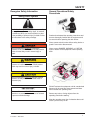
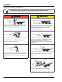
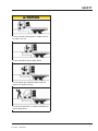
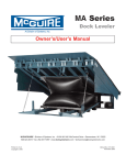
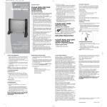
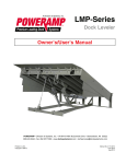
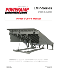
NMS
Mechanical Dock Leveler
Owner’s/User’s Manual
NOVA Technology International, Inc. | N90W14507 Commerce Drive Menomonee Falls, WI 53051
Phone 262-502-1591 | 800-236-7325 | fax 262-502-1511 | www.novalocks.com
Printed in USA
© 2010
Manual No. 4111-0019N
June 2010
November 2010
Table of Contents
Page
Safety
Recognize Safety Information . . . . . . . . . . . . . . . . . . . . . . . . . . . . . . .
General Operational Safety Precautions . . . . . . . . . . . . . . . . . . . . . .
Operational Safety Precautions . . . . . . . . . . . . . . . . . . . . . . . . . . . . .
Maintenance Safety Precautions . . . . . . . . . . . . . . . . . . . . . . . . . . . .
Safety Decals . . . . . . . . . . . . . . . . . . . . . . . . . . . . . . . . . . . . . . . . . . . .
Owner’s/User’s Responsibilities . . . . . . . . . . . . . . . . . . . . . . . . . . . .
1
1
2
4
5
6
Introduction
General Information . . . . . . . . . . . . . . . . . . . . . . . . . . . . . . . . . . . . . . . 7
Dock Leveler Stock Specifications . . . . . . . . . . . . . . . . . . . . . . . . . . . 7
Component Identification . . . . . . . . . . . . . . . . . . . . . . . . . . . . . . . . . . 8
Installation
Prepare Pit . . . . . . . . . . . . . . . . . . . . . . . . . . . . . . . . . . . . . . . . . . . . . . 9
Prepare Dock Leveler . . . . . . . . . . . . . . . . . . . . . . . . . . . . . . . . . . . . .10
Install Dock Leveler . . . . . . . . . . . . . . . . . . . . . . . . . . . . . . . . . . . . . . 12
Operation
Theory . . . . . . . . . . . . . . . . . . . . . . . . . . . . . . . . . . . . . . . . . . . . . . . . .
Operating Instructions . . . . . . . . . . . . . . . . . . . . . . . . . . . . . . . . . . . .
Ramp Loading/Unloading Instructions . . . . . . . . . . . . . . . . . . . .
End Loading/Unloading Instructions . . . . . . . . . . . . . . . . . . . . .
17
18
19
20
Maintenance
Service Dock Leveler Safely . . . . . . . . . . . . . . . . . . . . . . . . . . . . . . . 21
Periodic Maintenance . . . . . . . . . . . . . . . . . . . . . . . . . . . . . . . . . . . . . 22
Adjustments
Adjust Lift Arm Spring and Lip Assist Spring Tension . . . . . . . . . . 24
Adjust Lip Stop Bolt . . . . . . . . . . . . . . . . . . . . . . . . . . . . . . . . . . . . . . 26
Troubleshooting
Troubleshooting . . . . . . . . . . . . . . . . . . . . . . . . . . . . . . . . . . . . . . . . . 27
Parts
Hold-Down Mechanism . . . . . . . . . . . . . . . . . . . . . . . . . . . . . . . . . . .
Frame Components . . . . . . . . . . . . . . . . . . . . . . . . . . . . . . . . . . . . . .
Platform Components . . . . . . . . . . . . . . . . . . . . . . . . . . . . . . . . . . . .
Toe Guard/Weather Seal—Optional . . . . . . . . . . . . . . . . . . . . . . . . . .
29
30
32
36
Miscellaneous
Customer Information . . . . . . . . . . . . . . . . . . . . . . . . . . . . . . . . . . . . 37
Warranty . . . . . . . . . . . . . . . . . . . . . . . . . . . . . . . . . . . . . . . . Back Cover
4111-0019 —Nov.2010
SAFETY
Recognize Safety Information
General Operational Safety
Precautions
Safety-Alert Symbol
The Safety-Alert Symbol identifies important safety
messages on equipment, safety signs, in manuals,
or elsewhere. When you see this symbol, be alert
to the possibility of personal injury or death. Follow
the instructions in the safety message.
Read and understand the operating instructions and
become thoroughly familiar with the equipment and
its controls before operating the dock leveler.
Never operate a dock leveler while a safety device or
guard is removed or disconnected.
The use of the word DANGER signifies the
presence of an extreme hazard or unsafe practice
which will most likely result in severe injury or
death.
The use of the word WARNING signifies the
presence of a serious hazard or unsafe practice
which may result in serious injury or death.
The use of the word CAUTION signifies possible
hazard or unsafe practice which could result in
personal injury.
IMPORTANT
The use of the word IMPORTANT is to draw
attention to a procedure that needs to be followed
to prevent machine damage.
Never remove DANGER, WARNING, or CAUTION
signs or decals on the equipment unless replacing
them.
e
Op
ing
rat
ne
Zo
g
tin
era
p
O
Zo
ne
DO NOT activate the equipment until all unauthorized
personnel in the area have been warned and have
moved outside the operating zone.
Remove any tools or foreign objects from the
operating zone before starting.
Keep the operating zone free of obstacles that could
cause a person to trip or fall.
1
4111-0019 — NOV 2010
SAFETY
Operational Safety Precautions
Learn the safe way to operate this equipment. Read and understand the
manufacturer's instructions. If you have any questions, ask your supervisor.
Stay clear of dock leveling device when freight
carrier is entering or leaving area.
Chock/restrain all freight carriers. Never remove
the wheel chocks until loading or unloading is
finished and truck driver has been given
permission to drive away.
Do not move or use the dock leveling device if
anyone is under or in front of it.
Do not use a broken or damaged dock leveling
device. Make sure proper service and
maintenance procedures have been performed
before using.
Keep hands and feet clear of pinch points. Avoid
putting any part of your body near moving parts.
Make sure lip overlaps onto trailer at least 4 in.
(102 mm).
Keep a safe distance from both side edges.
2
4111-0019 — Nov. 2010
SAFETY
Do not use dock leveling device if freight carrier is
too high or too low.
Do not overload the dock leveling device.
Do not operate any equipment while under the
influence of alcohol or drugs.
Do not leave equipment or material unattended on
dock leveling device.
3
4111-0019 — NOV 2010
SAFETY
Maintenance Safety Precautions
DO NOT grind or weld if hydraulic fluid or other
flammable liquid is present on the surface to be
ground or welded
Always post safety warnings and barricade the
work area at dock level and ground level to
prevent unauthorized use of the unit before
maintenance is complete.
DO NOT grind or weld if uncontained hydraulic fluid
or other flammable liquid is present. Stray sparks
can ignite spills or leaks near the work area.
Always clean up the oil leaks and spills before
proceeding with grinding or welding.
Always keep a fire extinguisher of the proper type
nearby when grinding or welding.
Failure to follow these instructions may result in
serious personal injury or death.
ALWAYS stand clear of dock leveler lip when
working in front of the dock leveler. Failure to do
this may result in serious personal injury or death.
When engaging the maintenance prop
ensure the bridge pin is set in place and
closed before servicing or maintainning
the unit.
4
4111-0019 — Nov. 2010
Every 90 days (quarterly) inspect all safety labels and tags
to ensure they are on the dock leveler and are easily legible.
If any are missing or require replacement, please call
1-800-236-7325 for replacements.
OWNER’S/USER’S RESPONSIBILITIES
1. The owner/ user should recognize the inherent dangers of the interface between the
loading dock and the transportation vehicle. The owner/ user should, therefore, train and
instruct all operators in the safe operation and use of the loading dock equipment in
accordance with manufacturer’s recommendations and industry standards. Before
operation of the equipment, all operators shall read, understand and be familiar with all
functions of equipment as described in the owner’s/user’s manual.
2. The manufacturer shall provide to the initial purchaser all necessary information with
regards to: Safety Information, Operation, Installation and Safety Precautions,
Recommended Initial and Periodic Inspections Procedures, Planned Maintenance
Schedule, Product Specifications, Troubleshooting Guide, Parts Break Down, Warranty
Information and Manufacturers Contact Information. The owner/ user shall be responsible
to verify that this information is available and received as well as proper instructions,
training and familiarity of the equipment for all operators has been completed. Owner’s/
User’s shall actively maintain, update and re train all operators on safe working habits and
operations of the equipment.
3. It is recommended when the transportation vehicle is positioned correctly in the dock
opening and in contact with both bumpers, there shall be a minimum of 4.00 inches
(100mm) overlap of the leveling device and the transportation vehicle at all times during
the loading and unloading process.
4. Name plates, placards, decals, instructions and posted warnings shall not be obscured
from the view of the operator or maintenance personnel for whom such warnings are
intended for. Contact manufacturer for any replacements.
5. Manufacturer’s recommended periodic maintenance and inspection procedures in effect at
the date of shipment shall be followed at all times. Written documentation of maintenance,
replacement parts or damage should be retained. In the event of damage notification to
the manufacturer is requested.
6. Any modifications or alterations of loading dock equipment shall only be done with prior
written approval from the original equipment manufacturer.
7. When industrial moving devices are being used in the loading or unloading of product
from the transportation vehicle, this vehicle shall have the brakes and wheel chocks
applied appropriately or all other positive restraining device shall be fully utilized.
8. Loading dock safety equipment should never be used outside of its intended use, range,
or capacity. Please consult the manufacturer if you have any questions as to the use,
range or capacity of the equipment.
9. When selecting loading dock safety equipment, it is important to consider not only present
requirements but also future plans and any possible adverse conditions, environments or
use.
6
4111-0019 — Nov. 2010
NMS Series Mechanical Dock Levelers dock levelers
are available in the following sizes, weight
capacities, and options:
Congratulations on your choice of a NOVA dock
leveler. This manual covers the NMS-series
mechanical dock leveler.
Designed by NOVA to be a marvel of simplicity and
efficiency, your dock leveler, when properly installed,
will provide many years of trouble-free performance
with an absolute minimum of maintenance. To obtain
maximum performance and longest possible use, a
simple program of preventive maintenance is
recommended.
Once again, thank you and congratulations on your
purchase of a NOVA mechanical dock leveler.
Call NOVA for your specific needs.
INTRODUCTION
Component Identification
1
2
3
4
5
— Lip
— Lip Maintenance Prop
— Platform
— Lip Link
— Lip Assist Spring
8
6 — Hold Down Release Ring
7 — Ratchet Pawl
8 — Ratchet Bar
9 — Hold Down
10 — Platform Maintenance
Prop
11— Main Base Frame
12 — Safety Leg Assy.
13 — Lip (Snubber) Spring
14 — Lip Shock Absorber
15— Safety Leg Pull Chain
16 — Lift Arm Assembly
17 — Lift (Main) Spring
18 — Prop. Pin and Clip
19 — Working Range Toe
Guards
4111-0019 — Nov -2010
If any measurement is off by more than 1/8 in.
(3.18 mm), contact NOVA Technical Services
before proceeding.
NOVA dock levelers are designed with installation
in mind. Each unit is shipped with lifting brackets (A)
fastened to the platform side joists.
INSTALLATION
1. Remove any bumpers that may be banded, or
bolted to the frame of the dock leveler.
DO NOT remove the shipping bands (B) around
the platform lip and leveler frame at this time.
IMPORTANT
DO NOT over-tighten the lifting bracket hardware.
Over-tightening can damage the weather seal, if
equipped.
4. Remove wood blocks that are attached to the
leveler frame before putting the dock leveler into
the pit.
5. To pick up the unit from the rear, slide forks into the
fork slots and under the cross member. Shown below.
6. To pick up the unit from the front, move forks closer
together and slide over the frame and under the cross
member. It may be necessary to unband the unit to
gain access to the front, by lifting the lip up then
sliding the forks under the cross member.
NOTE: Overall width of platform and lifting brackets
(A) must be kept to a minimum to prevent
interference between the lifting brackets and
the pit walls as the dock leveler is lowered
into the pit.
2. Make sure the mounting hardware of lifting
brackets (A) is snug. The brackets should pivot
relatively freely on the mounting cap screw. DO
NOT over-tighten.
3. Attach lifting chains to lifting brackets (A) and to a
lifting device (i.e., hoist or fork truck) having the
appropriate lifting capacity and reach.
REAR PICK UP
FRONT PICK UP
11
4111-0019 — NOV 2010
INSTALLATION
Install Dock Leveler
Shim
Stacking Methods
M
N
P
Q
A— Distance (Leveler Frame
Height)
B— Shim Locations (Under
Rear Vertical Supports,
4-5 Places TYP)
C— Shim Locations (Under
Lip Keepers, Lifter Arm
and Prop)
D— Dock Floor
E— Rear Pit Curb Angle
12
F— String
G— Rear Hinge Frame Angle
H— Distance (Dock Floor-toPit Floor)
J— Distance (Top of Shim
Stack-to-Dock Floor)
K— Shim Stack
L— Dock Leveler Frame
M — Pyramid (Preferred)
N— Stepped (Acceptable)
P— Offset (Not Acceptable)
Q — Straight (Not Acceptable)
4111-0019 — Nov. 2010
NOTE: NOVA dock levelers are designed with a
nominal 1/2 in. (12.7 mm) shimming distance
to allow for pit inconsistencies.
12. If leveler cannot be squared and made level as
instructed in steps 8 – 10, contact NOVA
Technical Services.
19. If binding occurs, reposition leveler and/or add or
remove shims as necessary. Raise and lower
platform again. If platform still binds, contact
NOVA Technical Services for further
instructions.
INSTALLATION
A— Platform Release Ring
B— Platform Maintenance C —Lip prop support
Prop
21. Pull the release ring (A) to raise platform. Engage
the platform maintenance prop (B) in the service
(upright) position and lock the maintenance prop
at this position using an OSHA approved locking
device, supplied by others Engage lip
maintenance prop(C).
Make sure the platform is properly supported in the
raised position before entering the pit to finish weld
the shims. Failure to do this may result in serious
personal injury or death.
22. Install shims under lift arm at locations using the
pyramid shimming method. (Page 12)The lift arm
pivot must be solidly shimmed the entire length of
the lift arm pivot. Make sure the lift arm pivot is
level from side-to-side.
D — Prop Pin and Clip E —Safety Leg Pull
Chain
25. Remove the lifting brackets from the platform side
joists.
26. Disengage the platform maintenance prop.
27. Slowly walk out onto the platform to lower the
platform until it is at the cross-traffic (stored)
position.
28. Check operation of dock leveler by cycling the
leveler at least four times.
• When the platform is at full height, lip will be
fully extended.
• Lip will begin to drop after the unit begins to
lower to truck bed.
29. Check below-dock position by walking platform
down before lip folds completely.
• Lip will be over lip keepers.
• Platform safety legs will be resting on frame.
23. Finish weld all shims using a fillet weld.
• Weld all shims within each shim stack to each
other, then weld the shim stack to the leveler
frame.
• Weld the front leveler frame shim stacks to the
front pit curb steel if not done previously.
24. When all welding has been completed, remove all
slag then paint all the welds and shims.
16
30. Check full below-dock position by walking the
platform down. Pull and hold safety leg chain (E)
before lip folds completely.
31. If the lip does not extend fully or lip folds too
quickly, see appropriate symptom in the
Troubleshooting section.
32. Install the dock bumpers as required, clean
weld splatter and touch up with spray paint.
4111-0019 — Nov. 2010
The NMS-series mechanical dock leveler uses large
lift springs (18) to apply force to lift arm (17). The lift
arm pushes against the underside of the platform (3),
rolling on the cam (not pictured) forcing the platform
to rise. The force of the spring tension is just enough
to lift the weight of the platform and extend lip.
OPERATION
Operating Instructions
Stay clear of dock leveler when freight carrier is
entering or leaving dock area.
12 in. (305 mm)
DO NOT raise or lower the dock leveler if anyone is
under or in front of leveler.
12 in. (305 mm)
Keep hands and feet clear of pinch points. Avoid
putting any part of your body near moving parts.
Failure to follow these instructions may result in
severe personal injury or death.
DO NOT activate the dock leveler until the
truck/trailer is positioned squarely against the
bumpers and the truck wheels are chocked.
The MP-series mechanical dock leveler is designed
to compensate for ± 12 in. (305 mm) of height
difference between the loading dock and the truck
bed. DO NOT use the dock leveler if the truck/trailer
bed is more than 12 in. (305 mm) higher or lower
than the dock floor.
DO NOT overload the dock leveler.
DO NOT operate any equipment while under the
influence of alcohol or drugs.
Never remove the wheel chocks until loading and
unloading is finished and truck driver has been
given permission to leave.
DO NOT leave/store equipment or material
unattended on the dock leveler.
DO NOT use the dock leveler if the freight carrier is
too high or too low.
Failure to follow these instructions may result in
personal injury and/or damage to equipment.
NEVER use a fork truck or any other material
handling equipment to lower the dock leveler.
DO NOT drive any equipment onto the dock leveler
until platform lip is resting on the truck/trailer with
at least 4 in. (102 mm) of overlap.
Always maintain a safe distance from side edges of
leveler during the loading and unloading process.
IMPORTANT
When activating the leveler, always pull AND hold
the platform release ring until the platform is at the
full-raised position. Releasing the ring while the
platform is still rising may result in damage to the
equipment.
NEVER attempt to walk on an unsupported lip.
NEVER allow untrained personnel to operate the
dock leveler.
The dock leveler operation instructions are
divided into the two methods of loading and
unloading:
NEVER attempt to lift any part of the leveler by
hand.
• For ramp loading and unloading, see Ramp
Loading/Unloading Instructions on page 19.
Failure to follow these instructions may result in
serious personal injury or death.
• For end loading and unloading, see End
Loading/Unloading Instructions on page 20.
18
4111-0019 — Nov. 2010
OPERATION
Operating Instructions — Continued
Ramp Loading/Unloading Instructions
NOTE: If end unloading is required, see End
Loading/Unloading Instructions on page 20.
1. Check to make sure truck/trailer is positioned
squarely against dock bumpers.
7. Make sure that the lip is fully extended and
supported on the truck/trailer along the entire
width of the platform with at least 4 in. (102 mm)
of lip contacting the truck bed.
2. Instruct driver to remain at the dock until the
loading or unloading process has been
completed.
3. Chock the truck/trailer wheels or use truck
restraint if present.
8. Proceed with loading or unloading.
A
NOTE: If end loading is necessary, see End
Loading/Unloading Instructions on page 20.
A
4. Raise the platform by pulling and holding the
platform release ring (A).
5. Hold the release ring until the platform is at the
fully-raised position and lip is fully extended.
9. When the loading or unloading process has been
completed, return platform to cross-traffic (stored)
position as follows:
a. Raise the platform to the full-raised position by
pulling and holding the platform release ring (A).
6. Walk out onto the platform. The platform will lower
until the lip rests on the truck/trailer bed.
b. Lower platform by slowly walking out onto the
platform allowing time for the lip to fully fold and
clear the truck/trailer. Continue walking out on
platform until platform lowers to the cross-traffic
position (lip engages in the lip keepers).
10. Remove chocks from truck/trailer wheels or
release truck restraint if used.
11. Indicate to driver that truck may leave the dock.
19
4111-0019 — NOV 2010
OPERATION
Operating Instructions — Continued
End Loading/Unloading Instructions
NOTE: End loading or unloading can be done with
the dock at the cross-traffic position or
below-dock position depending on the height
of the truck/trailer bed.
B
1. Check to make sure truck/trailer is positioned
squarely against dock bumpers.
2. Instruct driver to remain at the dock until the
loading or unloading process has been completed,
and instructed to leave.
3. Chock the truck/trailer wheels or use truck restraint
if present.
6. Slowly walk the platform down allowing enough
time for the lip to fold. Just before the platform
reaches the cross-traffic position, pull and hold
the safety leg retract pull ring (B) (located in a
recess at front of the platform). The platform will
continue lowering to the full below dock position.
End Loading/Unloading — Platform at Cross-Traffic Position.
End Loading/Unloading — Platform at Below-Dock Position.
4. If truck/trailer bed is at or above dock floor level,
leave leveler at the cross-traffic position and
proceed with loading or unloading. When finished,
perform steps 9 and 10.
7. Proceed with loading or unloading.
If truck/trailer bed is below the dock floor level,
perform steps 5 – 10.
A
NOTE: When end unloading is finished and
additional access to the truck/trailer requires
that the platform lip be extended, see Ramp
Loading/Unloading Instructions on page 19
for further instructions.
8. When loading or unloading is finished, raise the
platform to the full-raised position by pulling and
holding the platform release ring. Slowly walk the
platform down, allowing enough time for the lip to
fold. The platform will lower to the cross-traffic
position (lip engages in the lip keepers).
9. Remove chocks from truck/trailer wheels or
release truck restraint if used.
5. Pull and hold the platform release ring (A) until
the platform is at the fully-raised position.
20
10. Indicate to the driver that the truck may leave the
dock.
4111-0019 — Nov. 2010
MAINTENANCE
Service Dock Leveler Safely
A— Platform Release Ring B — Platform Maintenance Prop C— Lip Maintenance Prop D— Prop Pin and Clip E— Safety Leg Pull Chain
Always post safety warnings and barricade the
work area at dock level and ground level to prevent
unauthorized use of the dock leveler before
maintenance is complete. Failure to do this may
result in serious personal injury or death.
Always stand clear of the dock leveler lip when
working in front of the dock leveler. Failure to do
this may result in serious personal injury or death.
The platform maintenance prop MUST be in the
service position when working under the dock
leveler. For maximum protection, use an OSHA
approved lock out tag out device.supplied by
others, to lock the maintenance prop in the service
position. Only the person servicing the equipment
should have the key to unlock the maintenance
prop.
Whenever maintenance is to be performed under the
dock leveler platform, support the platform with the
platform maintenance prop (B).
Put the platform maintenance prop in the service
(upright) position so that the prop is cradled in back
of the header plate and the underside of the deck
plate. Secure the platform maintenance prop in this
position by inserting the pin or attaching an OSHA
approved lockout device* and tagout device*,
supplied by others .
Only the person servicing the equipment should have
the capability to remove the lockout device. The
tagout device must inform that repairs are in process
and clearly state who is responsible for the lockout
condition.
If maintenance requires that the lip be in the
extended position, raise the lip by hand and support
the lip with the lip maintenance prop (C).
NOTE: Make sure to disengage the lip maintenance
prop and allow the lip to fold fully before
disengaging the platform maintenance prop.
Failure to follow these instructions may result in
serious personal injury or death.
* Refer to OSHA regulation 1910.147.
21
4111-0019 — NOV 2010
MAINTENANCE
Periodic Maintenance
1 — Lip Hinge Grease Fittings
2 — Lip Maintenance Prop Pivot
3 — Lift Arm Roller Bushing
4 — Lift Arm Pivot
5 — Hold-Down Pivot/Pulley
6— Safety Leg Linkage Pivots
Always post safety warnings and barricade the
work area at dock level and ground level to prevent
unauthorized use of the dock leveler before
maintenance is complete. Failure to do this may
result in serious personal injury or death.
Always stand clear of the dock leveler lip when
working in front of the dock leveler. Failure to do
this may result in serious personal injury or death.
22
7 — Lip Lift Assist Pin
8 — Hold Down-to-Platform Pin
The platform maintenance prop MUST be in the
service position when working under the dock
leveler. For maximum protection, use an OSHA
approved locking device to lock the maintenance
prop in the service position, supplied by others.
Only the person servicing the equipment should
have the key to unlock the maintenance prop.
Failure to follow these instructions may result in
serious personal injury or death.
4111-0019 — Nov. 2010
MAINTENANCE
Regular maintenance must be performed on a weekly
and quarterly schedule.
Weekly Maintenance
Quarterly Maintenance
• Operate the dock leveler through the complete
operating cycle to maintain lubrication.
• Lubricate the following areas with light-weight
machine oil:
NOTE: To thoroughly inspect the platform hinge area,
position the platform in the full below-dock
position.
(2)— Lip maintenance prop pivot
• Inspect the platform hinge and the lip hinge areas.
The hinge areas must be kept free of dirt and
debris. Build-up of foreign material in the hinge
areas will increase wear and cause abnormal
operation.
(6)— Safety leg linkage pivots
(5)— Hold-down pivot/pulley
(8)— Hold down-to-platform pin
• Lubricate the following areas with white lithium
grease:
IMPORTANT
Failure to properly lubricate the dock leveler will
cause abnormal operation of the leveler.
(1)— Lip hinge area (inject grease into all the lip
hinge grease fittings)
(3)—Lift arm roller bushing
DO NOT lubricate the hold-down ratchet bar and
pawl.
(4)— Lift arm pivot
(7)— Lip assist pin
23
4111-0019 — NOV 2010
ADJUSTMENTS
Adjust Lift Arm Spring and Lip Assist Spring Tension
1 — Jam Nut
2 — Adjustable Nut
3 — Lip Assist Spring
4— Lift Springs
Always post safety warnings and barricade the
work area at dock level and ground level to prevent
unauthorized use of the dock leveler before
maintenance is complete. Failure to do this may
result in serious personal injury or death.
Always stand clear of the dock leveler lip when
working in front of the dock leveler. Failure to do
this may result in serious personal injury or death.
24
5 — Lift Spring Bolt
6 — Hold-Down Mechanism
The platform maintenance prop MUST be in the
service position when working under the dock
leveler. For maximum protection, use an OSHA
approved locking device to lock the maintenance
prop in the service position supplied by others.
Only the person servicing the equipment should
have the key to unlock the maintenance prop.
Failure to follow these instructions may result in
serious personal injury or death.
4111-0019 — Nov. 2010
ADJUSTMENTS
NOTE: Adjusting the tension of lift springs (4) usually
requires that the lip assist spring (3) also be
adjusted.
If the platform does not rise fully and/or lip does not
extend fully, the lift spring tension may be set too low.
If the platform cannot be walked down or is difficult to
walk down, the lift spring tension may be set too high.
3. After lift spring adjustment is completed, check
operation of the lip.
• If the lip folds before the platform can be
walked down, tension of lip assist spring (3)
may be set too low.
• If the lip does not fold fully or takes too long to
fold, tension of lip assist spring (3) may be set
too high.
4. Adjust lip assist spring tension as follows:
If the platform does not rise fully on its own, it may
be necessary to use an external lifting device. Use
a lifting device with the appropriate lifting capacity
to safely raise the platform. Make sure to engage
and pin the platform maintenance prop after raising
the platform. Failure to do this may result in serious
personal injury or death.
IMPORTANT
When using an external lifting device to raise the
platform, make sure hold-down mechanism (6) is
disengaged. Pull and hold platform release ring
during the lifting process to avoid shearing the
ratchet pawl and ratchet bar teeth.
1. Raise the platform and engage the platform
maintenance prop. Pin the maintenance prop in
the service position using attached pin device.
NOTE: Use two-turn increments when adjusting lip
assist spring (3). Check lip operation after
each adjustment. Repeat until proper
operation is obtained.
a. Loosen jam nut (1).
b. To increase spring compression, turn nut (2)
clockwise.
c. To decrease spring compression, turn nut (2)
counterclockwise.
d. Tighten jam nut.
5. Recheck operation of platform and lip. Readjust lift
spring tension and lip assist spring tension until
proper operation is obtained.
2. Adjust tension of lift springs (4) as follows:
NOTE: Use 1/2 turn increments when adjusting lift
spring bolt (5).Turn clockwise to increase
tension and counterclockwise to decrease
tension. Check platform operation after each
adjustment. Repeat until proper operation is
obtained.
• To increase lift spring tension, turn lift spring
bolt (5) clockwise.
• To decrease lift spring tension, turn lift spring
bolt (5) counterclockwise.
25
4111-0019 — NOV 2010
ADJUSTMENTS
Adjust Lip Stop Bolt
Always post safety warnings and barricade the
work area at dock level and ground level to prevent
unauthorized use of the dock leveler before
maintenance is complete. Failure to do this may
result in serious personal injury or death.
A
B
Always stand clear of the dock leveler lip when
working in front of the dock leveler. Failure to do
this may result in serious personal injury or death.
C
E
D
The platform maintenance prop MUST be in the
service position when working under the dock
leveler. For maximum protection, use an OSHA
approved locking device, supplied by others, to lock
the maintenance prop in the service position. Only
the person servicing the equipment should have
the key to unlock the maintenance prop.
Failure to follow these instructions may result in
serious personal injury or death.
Check that lip (E) is fully resting on the lip keepers
(D) and at the lowest part of the lip keepers. If lip is
not resting properly in lip keepers, perform the
following adjustment.
1. Fully raise platform. Manually raise the lip and
engage lip maintenance prop (not shown).
2. Loosen jam nut (B).
A— Platform
B— Jam Nut
C— Stop Bolt
D — Lip Keeper
E — Lip
4. Tighten jam nut (B).
5. Disengage lip maintenance prop.
6. Walk platform down to cross-traffic (stored)
position.
7. Check lip position in both keepers. Repeat
procedure if necessary.
3. Adjust stop bolt (C) as necessary.
• Turn stop bolt “in” (clockwise) to allow lip to fold
closer to platform (A).
• Turn stop bolt “out” (counterclockwise) to hold
lip further away from platform (A).
26
4111-0019 — Nov. 2010
If no obstructions found, call NOVA Technical
Services. See cover for phone number and
address.
If no obstructions found, call NOVA Technical
Services. See cover for phone number and
address.
TROUBLESHOOTING
Symptom
Platform rises to full
height, but lip does not
fully extend.
Possible Cause
Lip assist chain
disconnected or broken.
Connect or replace chain.
Insufficient main spring
tension.
Increase tension on main lift springs. (See Adjust Lift
Arm Spring and Lip Assist Spring Tension in the
Adjustments section.)
Insufficient lip assist force.
Increase lip assist spring compression. (See Adjust
Lift Arm Spring and Lip Assist Spring Compression
in the Adjustments section.)
Platform does not lower Excessive main spring
when operator walks out tension.
onto the platform.
Lip folds too fast during
normal walk-down.
Platform does not stay
down.
Lip does not fold after
truck departs.
28
Solution
Reduce main spring tension. (See Adjust Lift Arm
Spring and Lip Assist Spring Tension in the
Adjustments section.)
Damaged or worn
hold-down mechanism.
Clean and inspect hold-down mechanism.
Insufficient lip assist force.
Increase lip assist spring compression. (See Adjust
Lift Arm Spring and Lip Assist Spring compression
in the Adjustments section.)
Disconnected, worn, or
broken gas strut.
Inspect shock absorber. Connect or replace gas
strut.
Entangled release chain.
Remove cause of entanglement.
Dirt impacted in ratchet bar
teeth.
Clean and inspect ratchet bar and ratchet pawl
teeth. DO NOT lubricate the ratchet assembly.
Broken or damaged ratchet
assembly teeth.
Replace ratchet assembly. DO NOT lubricate the
ratchet assembly.
Disconnected or broken
hold-down pivot pins.
Replace hold-down pivot pins.
Damaged or worn
hold-down mechanism.
Clean and inspect hold-down mechanism.
Lip hinge binding because
of lack of lubrication
Inject grease into all of the lip hinge grease fittings.
(See Periodic Maintenance in the Maintenance
section.)
Excessive lip assist force.
Decrease lip assist spring compression. (See Adjust
Lift Arm Spring and Lip Assist Spring Compression
in the Adjustments section.)
4111-0019 — Nov. 2010
PARTS
Frame Components
30
4111-0019 — Nov. 2010
NVS2000AR
PARTS
Platform Components
PLATFORMS
ITEM QTY
1
32
6 FOOT
6.0 FOOT 6.5 FOOT 7.0 FOOT
8 FOOT
6.0 FOOT 6.5 FOOT
10 FOOT
7.0 FOOT
6.0 FOOT 6.5 FOOT 7.0 FOOT
1
25K 9515-5000 9515-5004 9515-5008 25K 9515-5012 9515-5016
9515-5020 25K 9515-5024 9515-5028 9515-5032
1
30K 9515-5001 9515-5005 9515-5009 30K 9515-5013 9515-5017
9515-5021 30K 9515-5025 9515-5029 9515-5033
1
35K 9515-5002 9515-5006 9515-5010 35K 9515-5014 9515-5018
9515-5022 35K 9515-5026 9515-5030 9515-5034
1
40K 9515-5003 9515-5007 9515-5011 40K 9515-5015 9515-5019
9515-5023 40K 9515-5027 9515-5031 9515-5035
1
45K 9515-5036 9515-5038 9515-5040 45K 9515-5042 9515-5044
9515-5046 45K 9515-5048 9515-5050 9515-5052
1
55K 9515-5037 9515-5039 9515-5041 55K 9515-5043 9515-5045
9515-5047 55K 9515-5049 9515-5051 9515-5053
4111-0019 — Nov. 2010
PARTS
Platform Components
2
1
DPLA-0338
LIP BANGER ASSY.
3
4
2
1
DPLA-0341
DPLA-0353
BAR
BELOW DOCK PULL CHAIN
9
1
DPLA-0343
BELOW DOCK CONTROL ASSY.
10
2
DOTH-2382
PIN, COTTER
11
1
DOTH-2074
BOLT, HEX 5/8-11 X 2.00
12
1
DOTH-2160
NUT, HEX 5/8-11
17
1
DPLA-0360
BDC PUSH ROD ASSY
18
1
DOTH-2060
BOLT SHOULDER
19
1
DOTH-2131
LOCK NUT
20
1
DOTH-6406
LIP ASSIST ROD
23
1
DOTH-2550
SPRING ,LIP ASSIST STD (CONSULT FACTORY)
24
1
DOTH-2546
SPRING ,LIP ASSIST HEAVY (CONSULT FACTORY)
25
1
DOTP-2006
LIP PROP BAR
26
1
DOTH-2062
SHOULDER BOLT
27
1
OTH-2131
LOCK NUT
28
2
OTH-2214
WASHER
29
1
DOTH-2547
SPRING COMPRESSION
30
1
DOTH-2582
SHOCK GAS
31
1
DOTH-2351
BOLT CLEVIS
32
2
DOTH-2374
PIN COTTER
33
4
DOTH-2210
WASHER, FLAT
34
2
DOTH-2163
LOCK NUT
LIP SHAFTS
2
DPLA-2101
6.0 FOOT
2
DPLA-2102
6.5 FOOT
2
DPLA-2103
7.0 FOOT
36
2
DOTH-2355
PIN , CLEVIS
37
2
DOTH-2373
PIN, COTTER
39
2
2101-0079
WASHER, FLAT
35
LIPS
38
6.0 FOOT
25K
30K
35K
40/45K
55K
1
16 0595-5000
0595-5009
0595-5018
0595-5027
0595-5036
1
18 0595-5001
0595-5010
0595-5019
0595-5028
0595-5037
1
20 0595-5002
0595-5011
0595-5020
0595-5029
0595-5038
1
16 0595-5003
0595-5012
0595-5021
0595-5030
0595-5039
1
18 0595-5004
0595-5013
0595-5022
0595-5031
0595-5040
20 0595-5005
0595-5014
0595-5023
0595-5032
0595-5041
1
16 0595-5006
0595-5015
0595-5024
0595-5033
0595-5042
1
18 0595-5007
0595-5016
0595-5025
0595-5034
0595-5043
1
20 0595-5008
0595-5017
0595-5026
0595-5035
0595-5044
6.5 FOOT
1
7.0 FOOT
1 Must
provide dock leveler serial number, platform size, capacity, any options and lip size when calling
or faxing orders.
33
4111-0019 — NOV 2010
PARTS
Platform Components
55
SEE CHART
DOTH-2570
SPRING MAIN 6620
56
SEE CHART
DOTH-2574
SPRING MAIN 6635
57
SEE CHART
DOTH-2576
SPRING MAIN 6820
58
SEE CHART
DOTH-2578
SPRING MAIN 6835
6 FOOT LONG
6.0 FOOT
25K
30K
35K
40K
45K
55K
16
(4)55
(4)55
(4)55
(4)55
(4)55
(1)55, (2)56
18
(4)55
(4)55
(4)55
(4)55
(4)55
(1)55, (2)56
20
(4)55
(4)55
(4)55
(4)55
(4)55
(1)55, (2)56
16
(4)55
(4)55
(4)55
(4)55
(4)55
(1)55, (2)56
18
(4)55
(4)55
(4)55
(4)55
(4)55
(1)55, (2)56
20
(4)55
(4)55
(4)55
(4)55
(4)55
(1)55, (2)56
16
(4)55
(4)55
(4)55
(4)55
(2)55, (2)56
(2)55, (2)56
18
(4)55
(4)55
(4)55
(4)55
(2)55, (2)56
(2)55, (2)56
20
(4)55
(4)55
(4)55
(4)55
(2)55, (2)56
(2)55, (2)56
6.5 FOOT
7.0 FOOT
8 FOOT LONG
6.0 FOOT
16
25K
30K
35K
40K
45K
55K
(4) 55
(4) 57
(4) 57
(4) 57
(4) 57
(4) 57
18
(4) 55
(4) 57
(4) 57
(4) 57
(4) 57
(4) 57
20
(4) 55
(4) 57
(4) 57
(4) 57
(2)57, (2)58
(2)57, (2)58
16
(4) 57
(4) 57
(4) 57
(4) 57
(2)57, (2)58
(2)57, (2)58
18
(4) 57
(4) 57
(4) 57
(2)57, (2)58
(2)57, (2)58
(2)57, (2)58
20
(4) 57
(4) 57
(4) 57
(2)57, (2)58
(2)57, (2)58
(2)57, (2)58
16
(4) 57
(4) 57
(4) 57
(4) 57
(2)57, (2)58
(4)58
18
(4) 57
(4) 57
(4) 57
(4) 57
(2)57, (2)58
(4)58
20
(4) 57
(4) 57
(4) 57
(2)57, (2)58
(2)57, (2)58
(4)58
25K
30K
35K
40K
45K
55K
16
(8) 57
(4) 57, (4) 58
(4) 57, (4) 58
(4) 57, (4) 58
(8) 58
(8) 58
18
(8) 57
(4) 57, (4) 58
(4) 57, (4) 58
(4) 57, (4) 58
(8) 58
(8) 58
20
(8) 57
(4) 57, (4) 58
(4) 57, (4) 58
(4) 57, (4) 58
(8) 58
(8) 58
16
(4) 57, (4) 58
(4) 57, (4) 58
(4) 57, (4) 58
(4) 57, (4) 58
(8) 58
(8) 58
18
(4) 57, (4) 58
(4) 57, (4) 58
(4) 57, (4) 58
(4) 57, (4) 58
(8) 58
(8) 58
20
(4) 57, (4) 58
(4) 57, (4) 58
(4) 57, (4) 58
(4) 57, (4) 58
(8) 58
(8) 58
16
(4) 57, (4) 58
(4) 57, (4) 58
(4) 57, (4) 58
(8) 58
(8) 58
(8) 58
18
(4) 57, (4) 58
(4) 57, (4) 58
(4) 57, (4) 58
(8) 58
(8) 58
(8) 58
20
(4) 57, (4) 58
(4) 57, (4) 58
(4) 57, (4) 58
(8) 58
(8) 58
(8) 58
6.5 FOOT
7.0 FOOT
10 FOOT LONG
6.0 FOOT
6.5 FOOT
7.0 FOOT
34
4111-0019 — Nov. 2010
PARTS
Toe Guard/Weather Seal—Optional
10
12
11
9
5
3
6
1
6
2
7
4
6 FOOT
*
8 FOOT
10 FOOT
1
1
0014-0062
TOE GUARD LH MIDDLE
0014-0070
TOE GUARD LH MIDDLE
0014-0078
TOE GUARD LH MIDDLE
2
1
0014-0066
TOE GUARD LH LOWER
0014-0074
TOE GUARD LH LOWER
0014-0082
TOE GUARD LH LOWER
3
1
0014-0064
TOE GUARD RH MIDDLE
0014-0072
TOE GUARD RH MIDDLE
0014-0080
TOE GUARD RH MIDDLE
4
1
0014-0068
TOE GUARD RH LOWER
0014-0076
TOE GUARD RH LOWER
0014-0084
TOE GUARD RH LOWER
5
2
OTH-2041
SCREW CAP
SAME
SAME
6
4
OTH-2207
WASHER
SAME
SAME
7
2
OTH-2131
LOCK NUT
*
1
DKIT-9179
FRTG COMPLETE R&L
SAME
DKIT-9180
FRTG COMPLETE R&L
SAME
DKIT-9181
FRTG COMPLETE R&L
9
2
DOTH-2841 CHANNEL WEATHER SEAL
DOTH-2840 CHANNEL WEATHER SEAL
DOTH-2843 CHANNEL WEATHER SEAL
10
2
DOTH-2824 T-RUBBER WEATHER SEAL
DOTH-2824 T-RUBBER WEATHER SEAL
CONSULT
FACTORY
11
2
DOTH-2822 BRUSH WEATHER SEAL
DOTH-2822 BRUSH WEATHER SEAL
CONSULT
FACTORY
12
2
DOTH-2821 EXTRUSION ALUM.
DOTH-2820 EXTRUSION ALUM.
CONSULT
FACTORY
35
4111-0019 — NOV 2010
This page intentionally left blank
36
4111-0019 — Nov. 2010
When you receive your NMS-series dock leveler, write
down the dock leveler model and serial number in the
form provided. This will help ensure safe keeping of
the numbers in the event the model/serial number
decal (A) becomes lost or damaged.
Also, write down NOVA’s job number, the company
that installed the dock leveler, and the original
owner’s name. This will all help to identify the specific
dock leveler if more information is required.
When ordering, use part numbers and description to
help identify the item ordered. Do not use “item”
numbers. These are only for locating the position of
the parts. Always give dock leveler MODEL NUMBER
and/or SERIAL NUMBER.
For service, call or contact:
NOVA Technology
N90W14507 Commerce Drive
Menomonee Falls, WI 53051
Phone: (800) 236-7325
Fax: (262) 502-1511
NOVA Job No.
STANDARD PRODUCT WARRANTY
NOVA Technology warrants that its products will be free from defects in design, materials and
workmanship for a period of one (1) year from the date of shipment. All claims for breach of
this warranty must be made within 30 days after the defect is or can with reasonable care, be
detected. In no event shall any claim be made more than 30 days after this warranty has
expired. In order to be entitled to the benefits of this warranty, the product must have been
properly installed, maintained and operated in accordance with all manufacturer’s recommendations and/or specified design parameters and not otherwise have been subject to abuse,
misuse, misapplication, acts of nature, overloading, unauthorized repair or modification,
application in a corrosive environment or lack of maintenance. Periodic lubrication, adjustment
and inspection in accordance with all manufacturers’ recommendations are the sole responsibility of the Owner/User.
In the event of a defect, as determined by NOVA Technology covered by this warranty, NOVA
Technology shall remedy such defect by repairing or replacing any defective equipment or
parts, bearing the cost for the parts, labor and transportation. This shall be exclusive remedy
for all claims whether based on contract, negligence or strict liability.
WARRANTY LIMITATIONS
THE ABOVE WARRANTIES ARE IN LIEU OF ANY OTHER WARRANTIES, WHETHER
EXPRESSED OR IMPLIED, INCLUDING BUT NOT LIMITED TO ANY IMPLIED WARRANTY
OF MERCHANTABILITY OR FITNESS FOR A PARTICULAR PURPOSE. SYSTEMS INC.
AND ITS SUBSIDARIES SHALL NOT IN ANY EVENT BE LIABLE TO ANYONE, INCLUDING
THIRD PARTIES, FOR INCIDENTAL, CONSEQUENTIAL OR SPECIAL DAMAGES OF ANY
KIND INCLUDING BUT NOT LIMITED TO, BREACH OF WARRANTY, LOSS OF USE, LOSS
OF PROFIT, INTERUPTION OF BUSINESS OR LOSS OF GOODWILL.
PRODUCT SPECIFIC WARRANTY
“NMS” SERIES LEVELER
In addition to the “Standard Product Warranty” provided with all NOVA Products, NOVA
Technology guarantees materials, components and workmanship to be free of defects for the
following extended periods:
•Structural Warranty – For a period of five (5) years from the date of shipment, product will
carry a prorated structural warranty. This warranty specifically applies to; the deck section, lip
section, frame, rear hinge assembly and front hinge assembly only. This warranty covers
structural repairs to or replacement of dock leveler at NOVA’s sole discretion and expense
including reasonable labor, materials, freight and travel. If NOVA determines replacement is
necessary, it will provide the original purchaser with a credit toward the purchase of the new
replacement NOVA product in the amount equal to the original purchase price of the warranted
product F.O.B. point of manufacture, discounted on a five year straight line basis by the
number of years of use prior to replacement.