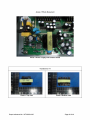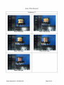
1
EN 60065:2002+A1: 2006 Clause Requirement – Test 3 GENERAL REQUIREMENTS P Safety class of the apparatus ................................. : Class II equipment P 4 GENERAL CONDITIONS OF TESTS P 4.1.4 Ventilation instructions require the use of the test box 5 MARKING 5.1 Result - Remark Verdict No, tested according to the instruction in the user’s manual P P Comprehensible and easily discernible The rating label is easily discernible. P Permanent durability against water and petroleum spirit After rubbing test by water and petroleum spirit, the label still easily discernible, indelible and legible. P Identification, maker, model ................................... : Trade mark: GIEC P Model number: GK-B001 Class II symbol if applicable Marked on the rear enclosure P Rated supply voltage and symbol .......................... : 220V-240V P Frequency if safety dependant P 50/60Hz Rated current or power consumption .................... : 10W P Earth terminal No earth terminal N Hazardous live terminals No hazardous live terminal N Supply output terminals (other than mains) No supply output terminal N 5.3 Use of triangle with exclamation mark Marked on the circuit diagram near every critical components P 5.4 Instructions for use Instruction for use provided in user’s manual in English P 5.4.1 Mains powered equipment not exposed to dripping Stated in the user’s manual or splashing. Warning concerning objects filled with liquid, etc. P Hazardous live terminals, instructions for wiring No hazardous live terminals N Instructions for replacing lithium battery No battery N Instructions for modem if fitted No modem provided N Class I earth connection warning Not class I equipment N 5.2 Instructions for multimedia system connection N Special stability warning for fixed installation Not fixed installation N Warning: battery exposure to heat No battery N Warning: protective film on CRT face No CRT N Report reference No.: WT093001905 Page 4 of 49 EN 60065:2002+A1: 2006 Clause Requirement – Test Result - Remark Verdict 5.4.2 Disconnect device: plug/coupler or all-pole mains switch location, accessibility and markings Power plug used as disconnect device P Instructions for permanently connected equipment Not permanently connected equipment N 6 HAZARDOUS RADIATION 6.1 Ionizing radiation < 36 pA/kg (0,5 mR/h) 6.1 European Council Directive 96/29/Euratom of 13 May 1996 10cm from outer surface of apparatus <1µSv/h (0,1mR/h) N Laser radiation, emission limits to IEC 60825-1 .... : No laser radiation N Emission limits under fault conditions .................... : N 7 HEATING UNDER NORMAL OPERATING CONDITIONS P 7.1 Temperature rises not exceeding specified values, (see appended table) no operation of fuse links P 7.1.1 Temperature rise of accessible parts (see appended table) P 7.1.2 Temperature rise of parts providing electrical insulation (see appended table) P 7.1.3 Temperature rise of parts acting as a support or as a mechanical barrier 7.1.4 Temperature rise of windings (see appended table) P 7.1.5 Parts not subject to a limit under 7.1.1 to 7.1.4 (see appended table) P 7.2 Softening temperature of insulating material supporting parts conductively connected to the mains carrying a current > 0,2 A at least 150 oC The input current was less than 0.2A N 8 CONSTRUCTIONAL REQUIREMENTS WITH REGARD TO THE PROTECTION AGAINST ELECTRIC SHOCK P 8.1 Conductive parts covered by lacquer, paper, untreated textile oxide films and beads etc. considered to be bare Compliance checked by inspection P 8.2 No shock hazard when changing voltage setting device, fuse-links or handling drawers etc. No voltage setting device. It is not possible for user to access fuse-links. No indicators and drawers used. N 8.3 Insulation of hazardous live parts not provided by hygroscopic material No hygroscopic material used as insulation P 8.4 No risk of electric shock following the removal of a cover which can be removed by hand There is no risk of an electric shock from accessible parts P 8.5 Class I equipment Not class I equipment N EN 60065 6.2 Report reference No.: WT093001905 N No ionizing radiation N N Page 5 of 49 EN 60065:2002+A1: 2006 Clause 8.6 8.8 8.9 Requirement – Test Result - Remark Verdict Basic insulation between hazardous live parts and earthed accessible parts N Resistors bridging basic insulation complying with 14.1 a) N Class II equipment and Class II constructions within Class I equipment P Reinforced or double insulation between hazardous live parts and accessible parts Reinforced or double insulation between hazardous live part and accessible parts P Components bridging reinforced or double insulation complying with 14.1 a) or 14.3 Transformer T1 bridging primary and secondary circuit complying with 14.3 P Basic and supplementary insulation each being bridged by a capacitor complying with 14.2.1 a) No such capacitor used N Reinforced or double insulation being bridged with 2 capacitors in series complying with 14.2.1 a) No such capacitor used N Reinforced or double insulation being bridged with a single capacitor complying with 14.2.1 b) Y1 capacitor separately approved used P Basic insulation bridged by components complying Not used with 14.3.4.3 N Basic or supplementary insulation > 0,4 mm (mm) : The insulation of the primary wire: 0.4mm+0.42mm P Reinforced insulation > 0,4 mm (mm) .................... : Enclosure (plastic): 2.3mm min P Thin sheet insulation (excluding non-separable thin sheet insulation. See 8.22) N Basic or supplementary insulation, at least two layers, each meeting 10.3 N Basic or supplementary insulation, three layers any two of which meet 10.3 N Reinforced insulation, two layers each of which meet 10.3 N Reinforced insulation, three layers any two which meet 10.3 N Adequate insulation between internal hazardous live conductors and accessible parts Primary internal wire separate from accessible parts by double insulation P Adequate insulation between internal hazardous live parts and conductors connected to accessible parts Internal hazardous live parts separate form conductors connectors connected to accessible part by double insulation P Report reference No.: WT093001905 Page 6 of 49 EN 60065:2002+A1: 2006 Clause Requirement – Test Result - Remark Verdict 8.10 Double insulation between conductors connected to the mains and accessible parts. Double insulation used P Wires are well secured. No wire is likely to become detached. See above P Double insulation between internal hazardous live parts and conductors connected to accessible parts. 8.11 Detaching of wires No undue reduction of creepages or clearance distances if wires become detached Vibration test carried out ........................................ : See 12.1.2 N P No such part 8.13 Adequate fastening of windows, lenses, lamp covers etc. (pull test 20 N for 10 s) N 8.14 Adequate fastening of covers (pull test 50 N for 10 s) 8.15 No risk of damage to the insulation of internal wiring due to hot parts or sharp edges Internal wire well secured and not likely to touch the hot parts or sharp edge P 8.16 Only special supply equipment can be used Not such equipment N 8.17 Insulated winding wire without additional interleaved insulation Triple insulation wire used as the secondary coil of the transformer P 8.18 Endurance test as required by 8.17 The triple insulation wire has been separately approved N 8.19 Disconnection from the mains See below P 8.19.1 Disconnect device Power plug used as disconnect device P All-pole switch or circuit breaker with >3mm contact separation No switch N P 8.19.2 Mains switch ON indication N 8.20 Switch not fitted in the mains cord N 8.21 Bridging components comply with clause 14 No such component used N 8.22 Non-separable thin sheet material No such material used N 9 ELECTRIC SHOCK HAZARD UNDER NORMAL OPERATING CONDITIONS P 9.1 Testing on the outside P 9.1.1 For voltages >1000 V ac or >1500 V dc complies with clause 13.3.1 for basic insulation 9.1.1.1 a) Open circuit voltages P b) Touch current measured from terminal devices Results in appended table using the network in annex D ................................. : 9.1.1. The measuring network P No voltage >1000 V ac or >1500 V dc according to annex D. Report reference No.: WT093001905 Page 7 of 49 N EN 60065:2002+A1: 2006 Clause Requirement – Test Result - Remark Verdict c) Discharge not exceeding 45 µC < 1µC P d) Energy of discharge not exceeding 350 mJ No voltage exceeding 15 kV dc. N 9.1.1.2 Test with test finger and test probe No hazard live parts accessible P 9.1.2 No hazardous live shafts of knobs, handles or levers No hazardous live shafts 9.1.3 Ventilation holes and other holes tested by means of 4 mm x 100 mm test pin No openings on top enclosure 9.1.4 Terminal devices tested with 1 mm x 20 mm test pin (10 N); test probe D of IEC 61032 No hazard live parts accessible Terminal devices tested with 1 mm x 100 mm straight wire (1 N); test probe D of IEC 61032 No hazard live parts accessible P N P P 9.1.5 Pre-set controls tested with 2.5 mm x 100 mm test No pre-set controls pin (10 N); test probe C of IEC 61032 N 9.1.6 0V under normal condition No shock hazard due to stored charge on withdrawal of the mains plug; voltage (V) after 2 s : 0V under single fault condition P If C is not greater than 0,1 µF no test needed N a) Enclosure sufficiently resistant to external force P 9.1.7 Test probe 11 of IEC 61032 for 10 s (50 N) No damage P b) Test hook of fig. 4 for 10 s (20 N) No damage P c) 30 mm diameter test tool for 5 s (100 or 250 N) : No damage P 9.2 No hazard after removing a cover by hand N 10 INSULATION REQUIREMENTS P 10.1 Insulation resistance (MΩ) at least 2 MΩ min. after Surge test with 50 discharges at a rate of maximum 12/min surge test for basic and 4 MΩ min. for reinforced insulation ................................................................. : from a 1nF capacitor charged to 10 kV performed. Measured greater than 4M between the circuit connect to hazards parts and circuit not connect to hazards parts. P 10.2 Humidity treatment 48 h or 120 h ........................... : 48h P 10.3 Insulation resistance and dielectric strength between mains terminals P Insulation Resistance and dielectric strength across BASIC or SUPPLEMENTARY insulation (Class 1) N Insulation resistance and dielectric strength across (see appended table) REINFORCED insulation (Class II) P Report reference No.: WT093001905 No removable cover by hand Page 8 of 49 EN 60065:2002+A1: 2006 Clause Requirement – Test Result - Remark Verdict 11 FAULT CONDITIONS 11.1 No shock hazard under fault condition No electric shock during fault operation. P 11.2 Heating under fault condition No excessive temperature P No hazard from softening solder No solder softened during the test. N Flames extinguish within 10 seconds No flames in fault condition tests P P Soldered terminations not used as protective mechanism P 11.2.1 Measurement of temperature rises (see appended table) P 11.2.2 Temperature rise of accessible parts (see appended table) P 11.2.3 Temperature rise of parts, other than windings, providing electrical insulation (see appended table) P Temperature rise of printed circuit boards (PCB) exceeding the limits of table 3 by max. 100 K for max. 5 min PCB temperature rise didn’t exceed the limits of table 3. N a) Temperature rise of printed circuit boards (PCB) to 20.1.3, exceeding the limits of table 3 by not more than 100 K for an area not greater than 2 cm² N b) Temperature rise of printed circuit boards (PCB) to 20.1.3 up to 300 K for an area not greater than 2 cm² for a maximum of 5 min N Meets all the special conditions if conductors on printed circuit boards are interrupted N Class I protective earthing maintained Not class I equipment N 11.2.4 Temperature rise of parts acting as a support or mechanical barrier (see appended table) P 11.2.5 Temperature rise of windings (see appended table) P 11.2.6 Temperature rise of parts not subject to the limits of 11.2.1 to 11.2.5 (see appended table) P 12 MECHANICAL STRENGTH 12.1.1 Bump test where mass >7 kg Less than 7 kg N 12.1.2 Vibration test No damage P 12.1.3 Impact hammer test 0.5J, three times. No damage P Steel ball test 2J on top, side back and front enclosure. No damage. P 12.1.4 Drop test for portable apparatus where mass < 7 kg Not portable apparatus N 12.1.5 Thermoplastic enclosures strain relief test 70℃ for 7h. No hazard live part become accessible P Report reference No.: WT093001905 P Page 9 of 49 EN 60065:2002+A1: 2006 Clause Requirement – Test Result - Remark Verdict 12.2 Fixing of knobs, push buttons, keys and levers 12.3 Remote controls with hazardous live parts No such remote controls N 12.4 Drawers (pull test 50 N, 10 s) No drawer N 12.5 Antenna coaxial sockets providing isolation No antenna coaxial socket providing isolation N 12.6 Telescoping or rod antennas construction No such device N 12.6.1 Telescoping or rod antennas securement No such device N 13 CLEARANCE AND CREEPAGE DISTANCES P 13.1 Clearances in accordance with 13.3 P Creepage distances in accordance with 13.4 P N 13.2 Determination of operating voltage Considered P 13.3 Clearances (see appended table) P 13.3.1 General P 13.3.2 Circuits conductively connected to the mains comply with table 8 and, where applicable, table 9 P 13.3.3 Circuits not conductively connected to the mains comply with table 10 P 13.3.4 Measurement of transient voltages N 13.4 Creepage distances (see appended table) P Creepage distances greater than table 11 minima P 13.5 Printed boards P 13.5.1 Clearances and creepage distances between conductors on printed circuit boards, one of which may be conductively connected to the mains, as in fig. 10 P 13.5.2 Type B coated printed circuit boards complying with IEC 60664-3 (basic insulation only) No such printed board used N 13.6 Conductive parts along uncemented joints clearances and creepage distances comply with 13.3 and 13.4 No such part N Conductive parts along reliably cemented joints comply with 8.8 N Temperature cycle test and dielectric strength test N 13.7 Enclosed, enveloped or hermetically sealed parts: not conductively connected to the mains: clearances and creepage distances as in table 12 N 13.8 Parts filled with insulating compound, meeting the requirements of 8.8 Report reference No.: WT093001905 Optocoupler separately approved Page 10 of 49 P EN 60065:2002+A1: 2006 Clause Requirement – Test Result - Remark 14 COMPONENTS P 14.1 Resistors N a) Resistors between hazardous live parts and accessible metal parts 14.2 Verdict No such component N b) Resistors, other than between hazardous live parts and accessible parts N Resistors separately approved .............................. : N Capacitors and RC units P Capacitors separately approved P nd 14.2.1 Y capacitors tested to IEC 60384-14, 2 edition .. : Y capacitors separately approved P 14.2.2 X capacitors tested to IEC 60384-14, 2nd edition .. : X capacitors separately approved P 14.2.3 Capacitors operating at mains frequency but not connected to the mains: tests for X2 ..................... : N 14.2.5 Capacitors with volume exceeding 1750 mm³, No such capacitor where short-circuit current exceeds 0,2 A: compliance with IEC60384-1, 4.38 category B or better ....................................................................... : N Capacitors with volume exceeding 1750 mm³, mounted closer to a potential ignition source than table 5 permits: compliance with IEC 60 384-1, 4.38 category B or better ........................................ : N Shielded by a barrier acc. to 20.1.4/ table 21 or metal ....................................................................... : N Inductors and windings P 14.3 Comply with IEC 61558-1, IEC 61558-2 (as relevant) and clause 20.1.4 14.3.1 14.3.2 Tested with the equipment N Transformers and inductors marked with Marked with the code manufacturer's name and type .............................. : P Transformers and inductors separately approved : Tested in unit N General P Insulation material complies with clause 20.1.4 Refer to 20.1.4 P 14.3.3 Constructional requirements 14.3.3.1 Clearances and creepage distances comply with clause 13 14.3.3.2 Transformers meet the constructional requirements P 14.3.4.1 Class II transformers have adequate separation Primary separately from between hazardous live parts and accessible parts secondary coil by reinforced (double or reinforced insulation) insulation P Report reference No.: WT093001905 P See clause 13 P Page 11 of 49 EN 60065:2002+A1: 2006 Clause Requirement – Test Result - Remark Coil formers and partition walls > 0,4 mm Bobbin of T1: > 0.9 mm P 14.3.4.2 Class I transformers, with basic insulation and protective screening only if all 7 conditions of 14.3.4.2 are met Class II transformer N 14.3.4.3 Separating transformers with at least basic insulation No separating transformer N 14.3.5.1 Class II transformers have adequate insulation Primary separately from between hazardous live parts and accessible parts secondary coil by reinforced (double or reinforced insulation) insulation P Coil formers and partition walls > 0,4 mm P 14.3.5.2 14.4 Verdict Bobbin of T1: > 0.9 mm Class I transformers have adequate insulation between hazardous live parts and accessible conductive parts or those conductive parts or protective screens connected to a protective earth terminal N Winding wires connected to protective earth have adequate current-carrying capacity N High voltage components No high voltage component N High-voltage components and assemblies: U > 4 kV (peak) separately approved N Component meets category V-1 of IEC 60707 N 14.4.1 High voltage transformers and multipliers tested as part of the submission N 14.4.2 High voltage assemblies and other parts tested as part of the submission N 14.5 Protective devices P Protective devices used within their ratings P External clearances and creepage distances meet See clause 13 requirement of clause 13 for the voltage across the device when opened P a) Thermal cut-outs separately approved N 14.5.1.1 No thermal cut-out b) Thermal cut-outs tested as part of the submission 14.5.1.2 a) Thermal links separately approved N No thermal link N b) Thermal links tested as part of the submission N 14.5.1.3 Thermal devices re-settable by soldering No such device N 14.5.2.1 Fuse-links in the mains circuit according to IEC 60127 Fuse link separately approved P 14.5.2.2 Correct marking of fuse-links adjacent to holder ... : “T 630mAL250V” marked near the fuse link on the PCB board P 14.5.2.3 Not possible to connect fuses in parallel ............... : P Report reference No.: WT093001905 Page 12 of 49 EN 60065:2002+A1: 2006 Clause Requirement – Test Result - Remark Verdict 14.5.2.4 Not possible to touch hazardous live parts when Tools need to replace the fuse replacing fuse-links without the use of a tool ......... : link N 14.5.3 PTC-S thermistors comply with IEC 60730-1 N No PTC-S thermistor PTC-S devices (15 W) category V-1 or better N 14.5.4 Circuit protectors have adequate breaking capacity and their position is correctly marked N 14.6 Switches 14.6.1 a) Separate testing to IEC 61058 including: No switch N N 10 000 operations Normal pollution suitability Resistance to heat and fire level 3 and Make and break speed independent of speed of actuation V-0 compliance with annex G, G.1.1 14.6.1 b) Tested in the apparatus: N Switch controlling > 0.2A with open contact voltage > 35 V (peak)/24 V dc complying with 14.6.3, 14.6.4 and V-0 in annex G, G.1.1 N Switch controlling > 0.2A with open contact voltage < 35 V (peak)/24 V dc complying with 14.6.3 and V-0 in annex G, G.1.1 N Switch controlling < 0.2A with open contact voltage > 35 V (peak)/24 V dc complying with 14.6.4 and V-0 in annex G, G.1.1 N 14.6.2 Switch tested to 14.6.1 b) constructed to IEC 61058-1 subclause 13.1 and has making/breaking action independent of speed of actuation N 14.6.3 Switch tested to 14.6.1 b) compliant with IEC 61058-1 subclause 16.2.2 d) and m) not attaining excessive temperatures in use N 14.6.4 Switch tested to 14.6.1 b) has adequate dielectric strength N 14.6.5 Mains switch controlling mains socket outlets additional tests to IEC 60058-1 N 14.7 Socket outlet current marking correct No socket outlet N Safety interlocks No such devices. N Safety interlocks to 2.8 of IEC 60950 14.8 Voltage setting devices and the like Report reference No.: WT093001905 N No such devices. N Page 13 of 49 EN 60065:2002+A1: 2006 Clause Requirement – Test Result - Remark Verdict Voltage setting device not likely to be changed accidentally N No motor 14.9 Motors 14.9.1 Endurance test on motors N Motor start test N Dielectric strength test N 14.9.2 Not adversely affected by oil or grease etc. N 14.9.3 Protection against moving parts N 14.9.4 Motors with phase-shifting capacitors, three-phase motors and series motors meet clause. B.8, B.9 and B.10 of IEC 60950, Annex B N 14.10 Batteries 14.10.1 Batteries mounted with no risk of accumulation of flammable gases N 14.10.2 No possibility of recharging non-rechargeable batteries N 14.10.3 Recharging currents and times within manufacturers limits N Lithium batteries discharge and reverse currents within the manufacturers limits N 14.10.4 Battery mould stress relief N 14.10.5 Battery drop test N 14.11 Optocouplers 14.12 N No battery used N Separately approved P Optocouplers comply with Cl. 8 P Internal and external dimensions to 13.1. or alternatively 13.6 (jointed insulation) P Surge suppression varistors No surge suppression varistor N Comply with IEC 61051-2 N Not connected between mains and accessible parts except for earthed parts of permanently connected apparatus N Complies with the current pulse, fire hazard and thermal stress requirements of 14.12 N 15 TERMINALS P 15.1.1 Mains plug, appliance inlet, interconnection couplers and mains socket-outlet meet the appropriate standard Report reference No.: WT093001905 Mains plug separately approved according to the appropriate standard Page 14 of 49 P EN 60065:2002+A1: 2006 Clause 15.1.2 Requirement – Test Result - Remark Verdict Overloading of plugs or appliance inlets prevented No mains socket outlet if the apparatus has mains socket outlets N Overloading of internal wiring prevented if the apparatus has mains socket outlets N No mains socket outlet Connectors for antenna, earth, audio, video or data: P No risk of insertion in mains socket-outlets None of mismatch of connectors to AC mains occurred. P No risk of insertion into audio or video: outlets marked with the symbol of 5.2 No sockets indicated with the symbol. N 15.1.3 Output terminals of a.c. adaptors or similar devices No such device not compatible with household mains socketoutlets N 15.2 Provision for protective earthing N Accessible conductive parts of Class I equipment reliably connected to earth terminal, within equipment Class II equipment N Protective earth conductors correctly coloured N Equipment with non-detachable mains cord provided with separate protective earth terminal near mains input N Protective earth terminal resistant to corrosion N Earth resistance test: < 0,1 Ω at 25 A ................... : N 15.3 Terminals for external flexible cords and for permanent connection to the mains supply P 15.3.1 Adequate terminals for connection of permanent wiring 15.3.2 Reliable connection of non-detachable cords: P Not soldered to conductors of a printed circuit board P Adequate clearances and creepage distances between connections should a wire break away Not permanent connected equipment No wire is likely to break away N P Wire secured by additional means to the conductor P 15.3.3 Screws and nuts clamping conductors have adequate threads: ISO 261, ISO 262 or similar N 15.3.4 Soldered conductors wrapped around terminal prior to soldering or held in place by additional means N Clamping of conductor and insulation if not soldered or held by screws N Report reference No.: WT093001905 Page 15 of 49 EN 60065:2002+A1: 2006 Clause Requirement – Test Result - Remark Verdict 15.3.5 Terminals allow connection of appropriate crosssectional area of conductors, for the rated current of the equipment N 15.3.6 Terminals to 15.3.3 have sizes required by table 16 N 15.3.7 Terminals clamp conductors between metal and have adequate pressure N Terminals designed to avoid conductor slipping out when tightened or loosened N Terminals adequately fixed to avoid loosening when the clamping is tightened or loosened and stress on internal wiring is avoided N 15.3.8 Terminals carrying a current more than 0,2 A: contact pressure not transmitted by insulating material except ceramic N 15.3.9 Termination of non-detachable cords: wires terminated near to each other P Terminals located and shielded: test with 8 mm strand N 15.4 Devices forming a part of the mains plug Not direct plug-in equipment N 15.4.1 No undue strain on mains socket-outlets 15.4.2 Device complies with standard for dimensions of mains plugs 15.4.3 Device has adequate mechanical strength (tests a,b,c) N 16 EXTERNAL FLEXIBLE CORDS P 16.1 VDE approved IEC 60227 Mains cords sheathed type, complying with PVC cord used IEC 60227 for PVC or IEC 60245 for synthetic rubber cords ............................................................ : P Non-detachable cords for Class I have green/yellow core for protective earth N N Class II equipment 16.2 Mains cords conductors have adequate cross0.5mm2, the length of the sectional area for rated current consumption of the power supply cord is less than equipment 2m 16.3 a) Flexible cords not complying with 16.1, used for interconnections between separate units of equipment used in combination and carrying hazardous live voltages, have adequate dielectric strength No such flexible cords. N b) Flexible cords not complying with 16.1, withstand bending and mechanical stress (3.2 of IEC 60227-2) No such flexible cords. N Report reference No.: WT093001905 Page 16 of 49 P EN 60065:2002+A1: 2006 Clause Requirement – Test 16.4 Flexible cords used for connection between No such flexible cord equipment have adequate cross-sectional areas to avoid temperature rise under normal and fault conditions N 16.5 Adequate strain relief on external flexible cords P Not possible to push cord back into equipment P Strain relief device unlikely to damage flexible cord P For mains cords of Class I equipment, hazardous live conductors become taut before earth conductor 16.6 Apertures for external flexible cord: no risk of damage to the cord during assembly or movement in use 16.7 Transportable musical instruments and amplifiers fitted with detachable cord set with appliance inlet to IEC 60320-1 Result - Remark Verdict Class II equipment N P Not transportable musical instrument N Transportable musical instruments and amplifiers fitted with detachable cord sets or with means of stowage to protect the cord N 17 ELECTRICAL CONNECTIONS AND MECHANICAL FIXINGS P 17.1 Torque test to table 20: P - screws into metal: 5 times Enclosure fixing and PCB fixing screws: Φ3.0mm, tested with 0.5Nm torque P - screws into non-metallic material: 10 times N 17.2 Correct introduction into female threads in nonmetallic material N 17.3 Cover fixing screws: captive No captive screw used N Non-captive fixing screws: no hazard when replaced by a screw whose length is 10 times its diameter No clearance and creepage distance will reduce to below the requirement. P 17.4 No loosening of conductive parts carrying a current > 0,2 A N 17.5 Contact pressure not transmitted through plastic other than ceramic for connections carrying a current > 0,2 A N 17.6 Stranded conductors of flexible supply cords carrying a current > 0,2 A with screw terminals not consolidated by solder N 17.7 Cover fixing devices other than screws have adequate strength and their positioning is unambiguous Report reference No.: WT093001905 No cover N Page 17 of 49 EN 60065:2002+A1: 2006 Clause Requirement – Test Result - Remark Verdict 17.8 Fixing devices for detachable legs or stands provided No such device N 17.9 Internal pluggable connections, affecting safety, unlikely to become disconnected N 18 MECHANICAL STRENGTH OF PICTURE TUBES AND PROTECTION AGAINST THE EFFECTS OF IMPLOSION N Picture tube separately approved to IEC 61965: N No picture tube Picture tube separately approved to 18.1 .............. : N Picture tubes > 16 cm intrinsically protected N Non-intrinsically protected tubes > 16 cm used with protective screen N Protective film as part of implosion protection: edges covered by enclosure N 18.2 Intrinsically protected tubes: tests on 12 samples N 18.2.1 Samples subject to ageing: 6 N 18.2.2 Samples subject to implosion test: 6 N 18.2.3 Samples subject to mechanical strength test (steel ball): 6 N 18.3 Non-intrinsically protected tubes tested to 18.3 N 19 STABILITY AND MECHANICAL HAZARDS P Mass of the equipment exceeding 7 kg ................. : Less than 7 kg N Apparatus intended to be fastened in place – suitable instructions N 19.1 Test on a plane, inclined at 10o to the horizontal N 19.2 100 N force applied vertically downwards N 19.3 100 N force, or 13% of weight, applied horizontally to point of least stability. N 19.4 Edges or corners not hazardous Edges and corners are smoothed P 19.5 Glass surfaces (exc.laminated) with an area exceeding 0,1 m² or maximum dimension > 450 mm, pass the test of 19.5.1 No glass surface N 19.6 Wall or ceiling mountings adequate N 20 RESISTANCE TO FIRE P 20.1 Electrical components and mechanical parts P 18.1 Report reference No.: WT093001905 Page 18 of 49 EN 60065:2002+A1: 2006 Clause Requirement – Test Result - Remark Verdict a) Exemption for components contained in an enclosure of material V-0 to IEC 60707 with openings not exceeding 1 mm in width N b) Exemption for small components as defined in 20.1 Some small components mounted on UL listed PCB with flammability of V-0. P 20.1.1 Electrical components meet the requirements of Clause 14 or 20.1.4 Considered complied for adapter itself. P 20.1.2 Insulation of internal wiring working at voltages > 4 kV or leaving an internal fire enclosure, not contributing to the spread of fire Internal wiring working at voltages not exceeding 4kV. N 20.1.3 Material of printed circuit boards on which the available power exceeds 15 W at a voltage between 50 V and 400V (peak) a.c. or d.c. meets V-1 or better to IEC60707, unless used in a fire enclosure V-0 PCB used P Material of printed circuit boards on which the See above available power exceeds 15 W at a voltage >400 V (peak) a.c. or d.c. meets V-0 to IEC 60707 20.1.4 Components and parts not covered by 20.1.1, 20.1.2 and 20.1.3 (other than fire enclosures) mounted nearer to a potential ignition source than the distances in Table 21 comply with the relevant flammability category in Table 21 P See clause 14 P Components and parts as above but shielded from a potential ignition source, with the barrier area in accordance with Table 21 and fig. 13 N 20.2 Fire enclosure N 20.2.1 Potential ignition sources with open circuit voltage > 4 kV (peak) a.c. or d.c. contained in a fire enclosure to V-1 No voltage > 4 kV. N 20.2.2 Internal fire enclosures with openings not exceeding 1 mm in width and with openings for wires completely filled No internal fire enclosure N 20.2.3 Requirements of 20.2.1 and 20.2.2 met by an internal fire enclosure Report reference No.: WT093001905 N Page 19 of 49 EN 60065:2002+A1: 2006 Clause Requirement – Test A APPENDIX A, ADDITIONAL REQUIREMENTS FOR APPARATUS WITH PROTECTION AGAINST SPLASHING WATER N A.5.1 j) Marked with IPX4 (IEC 60529), 5.4.1 a) does not apply N A.10.2.1 Enclosure provides protection against splashing water N A.10.2.2 Humidity treatment carried out for 7 days N B APPENDIX B, APPARATUS TO BE CONNECTED TO THE TELECOMMUNICATION NETWORKS N Complies with IEC 62151 clause 1 N Complies with IEC 62151 clause 2 N Complies with IEC 62151 clause 3 but with 3.5.4 modified to 2.4.10 of this standard N Complies with IEC 62151 clause 4 but with 4.1.2, 4.1.3 and 4.2.1.2 modified in accordance with annex B of this standard N Complies with IEC 62151 cause 5 but with 5.3.1 modified in accordance with annex B of this standard N Complies with IEC 62151 clause 6 N Complies with IEC 62151 clause 7 N Complies with IEC 62151 annex A, B and C N L APPENDIX L, ADDITIONAL REQUIREMENTS FOR ELECTRONIC FLASH APPARATUS FOR PHOTOGRAPHIC PURPOSES. N L5.4 Marking and Instructions N L9.1.1 Terminals to connection to synchroniser not HAZARDOUS LIVE N L7.1.5 & Lithium batteries meet permissible temp rise in Table 3, unless comply with 6.3.2 of IEC 60086-4 N Mains switch characteristics appropriate to its function under normal conditions N L11.2.6 L14.6.6 Report reference No.: WT093001905 Result - Remark Verdict Page 20 of 49 EN 60065:2002+A1: 2006 Clause Requirement – Test Result - Remark Verdict GROUP DIFFERENCES (CENELEC common modifications) and special national conditions according to CB Bulletin No. 112A, December 2006 P EN 60065:2002+A1:2006 (IEC Publication 60065:2001+A1:2005) EXPLANATION FOR ABBREVIATIONS C=CENELEC common modification, S=Special national conditon P=Pass, F=Fail, N/A=Not applicable. Placed in the column to the right CONTENT Add the following annexes: P Annex ZA (normative) Other international publications quoted in this standard with the references of the relevant European publications Annex ZB (normative) Special national conditions Annex ZC (informative) A-deviations 2.6.1 S(DK) Class II equipment P The following is added: Certain types of CLASS I apparatus, see 15.1.1, may be provided with a plug not establishing earthing continuity when inserted in Danish socket-outlets. Justification: Heavy Current Regulations, Section 107 3.1 N C: Add the following indent at the end of the list: exposure to excessive sound pressures from headphones or earphones. NOTE A new method of measurement is described in EN 50332-1, Sound system equipment: Headphones and earphones associated with portable audio equipmentMaximum sound pressure level measurement methodology and limit consideration- Part 1: General method for “one package equipment”, and in EN 50032-2, Sound system equipment: Headphones and earphones associated with portable audio equipment- Maximum sound pressure level measurement methodology and limit considerations- Part 2: Gudielines to associate sets with headphones coming from different manufactures. 4.1.1 C: Replace the text of the note by: N NOTE For ROUTINE TEST reference is made to EN 50333 5 S(DE) No cathode-ray tube The following marking are required: In case of intrinsically ionizing radiation safe cathode-ray tubes with accelerating voltages betwwen 20kV and 30kV: Report reference No.: WT093001905 Page 21 of 49 N EN 60065:2002+A1: 2006 Clause Requirement – Test Result - Remark Verdict - On the cathode-ray tube itself the wording: Eigensichere Kathodenstrahlröhre nach Anlage III Röntgenverordnung - Inside the apparatus: the maximum allowed accelerating voltage in kV, and the maximum allowed beam current in mA. - On the outer of the apparatus: a notice in German language that produced X-rays are sufficiently shielded by the intrinsically safe cathode-ray tube. In case of approval of the whole TV receiver with an accelerating voltage exceeding 20 kV: - On the outer of the apparatus: the licence number .../.../.../Rö, and the following text: Die in diesem Gerät entstehende Röntgenstrahlung ist ausreichend abgeschirmt. Beschleunigungsspannung: max: ... kV. - Supplied with the apparatus: a copy of the "Zulassungsschein", together with the notices required there. In case of TV receivers with accelerating voltages not exceeding 20 kV: Die in diesem Gerät entstehende Röntgenstrahlung ist ausreichend abgeschirmt. Beschleunigungsspannung: max: ... kV. Justification: German ministerial decree against ionizing radiation ( Röntgenverordnung), dated 1987-01-08. NOTE The German ministerial decree (Röntgenverordnung) is under revision. S(DE) No cathode-ray tube Annex ZC Delete the A-deviation for Clause 5 for Germany and add the following new A-deviation: Clause National deviation Germany Report reference No.: WT093001905 Page 22 of 49 N EN 60065:2002+A1: 2006 Clause Requirement – Test Result - Remark Verdict 6.1 The following requirement applies: For the operation of the any cathode ray tube intended for the display of visual images Operating at an acceleration voltage exceeding 40kV, authorization is required, or Application of type approval (Bauartzulassung) and marking. Justification: German ministerial decree against ionizing radiation (Röntgenverordnung), in force since 2002-07-01, implementing the European Directive 96/29/EURATOM. NOTE Contact address: Physikalisch-Tchnische Bundesanstalt, Bundesallee 100, D38116 Braunschweig, Tel.: Int+49-513-592-6320, Internet: http:// www.ptb.de 5.1 5.1.i) IT: additional marking on the outside of the TV receiver in Italian language Not TV receiver N IT: user instructions in Italian language including a conformity declaration N IT: certificatino number on the back cover N C: Replaced the note by: N NOTE For RATED POWER CONSUMPTION measurements of TVs reference is made to EN 62087. Measurements are done in the ON (play) operating mode. 5.4.1 C: Add the following indent: Za) A warning that excessive sound pressure from earphones and headphones can cause hearing loss Report reference No.: WT093001905 No earphone or headphone Page 23 of 49 N EN 60065:2002+A1: 2006 Clause Requirement – Test 6.1 C: Replace the subclause by: Result - Remark Verdict No ionizing radiation N 6.1 Ionizing radiation Equipment that might produce ionizing radiation is checked by measuring the amount of radiation. The amount of radiation is determined by means of a radiation monitor of the ionizing chamber type with an effective area of 1000m2 or by measuring equipment of other types giving equivalent result. Measurements are made with the equipment on test operating at the most unfavourable supply voltage (see 4.2) and with operator controls and service controls adjusted so as to give maximum radiation whilst maintainning the equipment operative for normal use. Internal preset controls not intended to be adjusted during the lifetime of the equipment are not considered to be serivce controls. At any point 100mm from the surface of the operator access area, the dose-rate shall not exceed 1μSv/h (0.1 mR/h) (see Note). Account shall be taken of the background level. NOTE These values appear in Directive 96/29/Euratom 13.3.1 C: Delete note 4 13.3.1 S (NO) P Considered P To the second paragraph the following is added: In Norway, due to the IT power distribution system used, the a.c. MAINS supply voltage is considered to be equal to the line-to-line voltage, and will remain 230V in case of a single earth fault will remain 230V in case of a single earth fault. Justification: Based on a use in Norway of an IT power distribution system where the neutral is not provided. 14 C: Delete not 4 and not 5. P 15.1.1 C: Delete note 1 and note 2. P 15.1.1 S (DK) No socket outlet used To the first paragraph the following is added: In Denmark, supply cords of single phase appliances having a rated current not exceeding 13A shall be provided with a plug according to the Heavy Current Refulations Section 107-2-D1. Appliances of CLASS I provided with socket-outlets with earth contact or which are intended to be used in locations where protection against indirect contact is required according to the wiring rules shall be provided with a plug in accordance with the Heavy Current Regulations, Section Report reference No.: WT093001905 Page 24 of 49 N EN 60065:2002+A1: 2006 Clause Requirement – Test Result - Remark Verdict 107-2-D1 standard sheet DK 2-1a. To the second paragraph the following is added: Socket outlets intended for providing power to CLASS II apparatus with a rated current of 2,5 A shall have the following dimensions: Dimensions in mm Other dimensions shall be in compliance with the Heavy Current Regulations, Section 107-2-D1, Standard Sheet DKA 1-3 for portable socket-outlets. Shutters are not required. To the third paragraph the following is added: Mains socket-outlets with earthing contact shall be in compliance with Heavy Current Regulations Section 107-2D1, Standard sheet DK 1-3a, DK 1-5a or DK 1-7a Justification: Heavy Current Regulations, Section 107 Report reference No.: WT093001905 Page 25 of 49 EN 60065:2002+A1: 2006 Clause Requirement – Test 15.1.1 S(NO) Result - Remark Verdict No socket-outlets N Mains socket-outlets mounted on CLASS II apparatus shall comply with the specifications given in CEE Publ. 7 as far as applicable, with the following amendments: § 8 Dimensions a 2,5 A 250 V two-pole socket-outlets for electronic apparatus shall comply with the enclosed Standard Sheet I. § 24 Mechanical strength a 2,5 A, 250 V socket-outlets for CLASS II electronic apparatus are tested as specified in 12.1.3 of EN 60065. Also the protecting rim shall be tested Justification: Act of 24 May 1929 relating to supervision of electrical installation (TEA 1929/FEL 1998). 15.2 C: Delete note 2. N 16.1 C: Delete note 1. N 16.2 C: Delete the note. N 20 C: Delete note 2. N Annex B C: Replace not 1 by: N In the CENELEC countries listed in IEC 62151, special national conditons apply. Add the following: All subclauses given below are subclauses of IEC 62151 Report reference No.: WT093001905 Page 26 of 49 EN 60065:2002+A1: 2006 Clause Requirement – Test Result - Remark Verdict (ref. corrigenda 1 and 2 to IEC 62151). Subclause 4.1.1 (corrigendum 2): Add after the first paragraph: NOTE In Finland, Norway and Sweden, CLASS I equipment which is intended for connection to the building installation via a non-industrial plug or a non-industrial appliance coupler, or both and in addition is intended for connection to other equipment or a network shall, if safety relies on connection to protective earth or if surge suppressors are connected between the network terminals and ACCESSIBLE parts, has a marking stating that the equipment must be connected to an earthed mains socketoutlet. The marking text in the applicable countries shall be as follows: In Finland: “Laite on liitettävä suojamaadoituskoskettimilla varustettuun pistorasiaan” In Norway: “Apparatet må tilkoples jordet stikkontakt” In Sweden: "Apparaten skall anslutas till jordat uttag" Subclause 4.1.4 (corrrigendum 1) Add at the end of the subclause: NOTE In Norway, for requirements see 4.1.1, note and 5.3.1, note 1. Subclause 4.2.1.2 (corrigendum 1) Add at the end of the subclause: NOTE 3 In Norway, for requirements see 5.3.1, note 1. Subclause 4.2.1.3 (corrigendum 2) Add at the end of the subclause: NOTE In Norway, for requirements see 4.1.1, note and 5.3.1, note 1. Subclause 4.2.1.4 (corrigendum 1) Number the existing note as NOTE 1 and add at the end of the subclause the following NOTE 2: NOTE 2 In Norway, for requirements see 4.1.1, note and 5.3.1, note 1. Subclause 5.3.1 (corrigendum 1) Add after the first test specifications paragraph: NOTE 1 In Finland, Norway and Sweden, there are additional requirements for the insulation. Renumber the existing note as NOTE 2. Report reference No.: WT093001905 Page 27 of 49 EN 60065:2002+A1: 2006 Clause Requirement – Test Result - Remark Verdict For additional requirements for the insulation in Finland, Norway and Sweden in NOTE 1 the following text is added between the first and the second paragraph (this text is identical to the corresponding EN 60950-1:2001): NOTE 1 In Finland, Norway and Sweden, if this insulation is solid, including insulation forming part of a component, it shall at least consist of either • two layers of thin sheet material, each of which shall pass the electric strength test below, or • one layer having a distance through insulation of at least 0,4 mm, which shall pass the electric strength test below If this insulation forms part of a semiconductor component (e.g. an optocoupler), there is no distance through insulation requirement for the insulation consisting of an insulating compound completely filling the casing, so that CLEARANCES and CREEPAGE DISTANCES do not exist, if the component passes the electric strength test in the accordance with the compliance clause below and in addition: • passes the test and inspection criteria of 13.6 with an electric strength test of 10.3 using the test voltage of 1,5 kV multiplied by 1,6, and • is subject to routine testing for electric strength during manufacturing, using a test voltage of 1,5 kV (for performance of the test see N.2.1). It is permitted to bridge this insulation with a capacitor complying with EN 132400:1994, subclass Y2. A capacitor classified Y3 according to EN 132400:1994, may bridge this insulation under the following conditions: • the insulation requirements are satisfied by having a capacitor classified Y3 as defined by EN 132400, which in addition to the Y3 testing, is tested with an impulse test of 2,5 kV defined in IEC 62151, Subclause 6.2.1; • the additional testing shall be performed on all the test specimens as described in EN 132400; • the impulse test of 2,5 kV is to be performed before the endurance test in EN 132400 in the sequence of tests as described in EN 132400. Subclause 5.3.2 (corrigendum 1) Add after the fourth dash: NOTE In Finland, Norway and Sweden, exclusions are applicable for equipment which is intended for connection to the building installation wiring using screw terminals or other reliable means, and for equipment which is intended for Report reference No.: WT093001905 Page 28 of 49 EN 60065:2002+A1: 2006 Clause Requirement – Test Result - Remark Verdict connection to the building installation wiring via an industrial plug and socket -outlet or an appliance coupler, or both, complying with EN 60309 or with a comparable national standard. S(SE) N 14 The following is added: Switches containing mercury such as thermostats, relays and level controllers are not allowed. Justification: Ordinance (1990:944) on Prohibition in Connection with Handling, Importation and Exportation of Chemical Products (Certain Cases) Annex G C: Delete the note N Annex J.2 C: Delete the notes of Table J.1. N J.2 After Table J.1 the following is added: N In Norway, due to the IT power distribution system used, the a.c. MAINS supply voltage is considered to be equal to the line-to-line voltage, and will remain 230 V in case of a single earth fault. Justification: Based on a use in Norway of an IT power distribution system where the neutral is not provided Annex N C: Add after the introduction: N For ROUTINE TEST reference is made to EN 50333. Bibliograph y C: Add the following standards: P EN 50332-1: 2000, Sound system equipment: Headphones and earphones associated with portable audio equipmentMaximum sound pressure level measurement methodology and limit considerations- Part 1: General method for “one package equipment”. EN 50332-2:2003, Sound system equiment: Headphones and earphones associated with portable audio equipemntMaximum sound pressure level measurement method and limit considerations-Part 1: General method for “one package equipemnt”. EN 50332-1: 2003, Sound system equipment: headphones and earphones associated with portable audio equipmentMaximum sound pressure level measruement- Maximum sound pressure level measurement methodology and limit consideration- Part 2: Matching of sets with headphones if either or both are offered separately EN 60065:2002/A1:2006 Add the following notes for the standards indicated: Report reference No.: WT093001905 Page 29 of 49 EN 60065:2002+A1: 2006 Clause Requirement – Test Result - Remark Verdict IEC 60130 (all parts) NOTE: Parts 9 and 17:1998 are harmonized as ENs (not modified). IEC 60169 (all parts) NOTE: Partly harmonized in the EN 60169/HD 134 series (not modified). IEC 60173:1964 NOTE: Harmonized as HD 27 S1:1978 (not modified). IEC 60335-2-56:1997 NOTE: Harmonized as EN 60335-256:1997 (not modified). IEC 60335-2-82:1999 NOTE: Harmonized as EN 60335-282:2000 (not modified). IEC 60410:1973 NOTE: Harmonized as EN 61040:1992 (not modified). IEC 60695 (all parts) NOTE: Harmonized as EN 60695 series (not modified). IEC 61040:1990 NOTE: Harmonized as EN 61040: 1992 (not modified) IEC 61558-2-1:1997 NOTE: Harmonized as EN 61558-21:1997 (not modified). IEC 61558-2-4:1997 NOTE: Harmonized as EN 61558-24:1997 (not modified). IEC 61558-2-6:1997 NOTE: Harmonized as EN 61558-26:1997 (not modified). IEC 61558-2-9: NOTE: Hamonized as EN 60598-29:1989+A1:1994 (not modified) IEC 61558-2-17 NOTE: Harmonized as EN 60598-2-17: 1989+A2:1991 (not modidied). Annex ZA P C: other international plublications quoted in this standard with the reference of the relevant European publications This European Standard incorporateds by dated or undated referenece. For dated references, subsequent amendments to or revisions of any of these publications apply to this European Standard only when iincorporated in it by amendment or revision. For undated references the lasted edition of the publication refered to applies (including amendments). NOTE When an international standard has been modified by common modification, indicated by (mod), the relevant EN/HD applies. Report reference No.: WT093001905 Page 30 of 49 EN 60065:2002+A1: 2006 Clause Requirement – Test Report reference No.: WT093001905 Result - Remark Verdict Page 31 of 49 EN 60065:2002+A1: 2006 Clause Requirement – Test Report reference No.: WT093001905 Result - Remark Verdict Page 32 of 49 EN 60065:2002+A1: 2006 Clause Requirement – Test Report reference No.: WT093001905 Result - Remark Verdict Page 33 of 49 EN 60065:2002+A1: 2006 Clause Requirement – Test Report reference No.: WT093001905 Result - Remark Verdict Page 34 of 49 EN 60065:2002+A1: 2006 Clause Requirement – Test Report reference No.: WT093001905 Result - Remark Verdict Page 35 of 49 7.1 TABLE: temperature rise measurements P Power consumption in the OFF/Stand-by 2.43W -- Position of the functional switch (W) ...................... : -- — Operating conditions Normal working Un (V) In (mA) Pn (W) Pout(W) 198V/50Hz 63.2 6.17 -- 220V/50Hz 61.5 6.30 -- 240V/50Hz 69.2 6.44 -- 264V/50Hz 56.0 6.63 -- 198V/60Hz 63.3 6.16 -- 220V/60Hz 63.0 6.29 -- 240V/60Hz 71.3 6.29 -- 264V/60Hz 56.4 6.66 -- Loudspeaker impedance (Ω) ............ -- — Several loudspeaker systems -- -- Marking of loudspeaker terminals -- Monitored point: dT (K) Limit dT (K) 198V/50Hz 264V/50Hz Power cord insulation 15.0 14.0 60 Connector CN6 16.6 15.5 For reference X2 cap C15 17.9 17.0 65 LF1 coil 21.9 21.2 75 PCB near D17 32.3 35.3 85 E-cap C123 34.7 38.2 70 PCB near U9 55.5 68.1 85 T1 coil 41.8 44.8 75 T1 bobbin 40.1 43.2 For reference PCB near D19 36.3 36.3 85 Optocoupler U10 34.4 36.6 65 Y-cap C133 34.9 37.5 70 PCB near U3 38.7 36.6 85 Top enclosure (metal) 11.3 10.2 40 Front enclosure (plastic) 7.7 6.3 60 Key 6.2 4.3 50 Report reference No.: WT093001905 Page 36 of 49 Operating conditions Winding temperature rise measurements N o Ambient temperature t1 ( C) .................................. : 24.1(198V), 24.3(264V) — Ambient temperature t2 (oC) .................................. : 24.4(198V), 25.3(264V) — Temperature rise dT of winding: R1 (Ω) R2 (Ω) dT (K) Limit dT (K) Insulation class Note: 7.2 TABLE: softening temperature of thermoplastics Temperature T of part 9.1.1 N T - normal conditions (oC) T - fault conditions (oC) T softening (oC) TABLE: Electric shock hazard under normal condition Measured between: P U1 (V) Required U1 (Vpk) U2 (V) Required U2 (Vpk) L/N and metal enclosure 0.190 35 0.168 0.35 L/N and signal terminal 0.196 35 0.172 0.35 10.3 TABLE: insulation resistance measurements P Insulation resistance R between: R (MΩ) Required R (MΩ) L and N (fuse open) >100 ≥2 L/N and signal terminal >100 ≥4 Primary and secondary coil of the T1 >100 ≥4 Secondary coil and the core of the T1 >100 ≥4 10.3 TABLE: electric strength measurements Test voltage applied between: P Test voltage (V) Breakdown L and N (switch open) 1500 No L/N and signal terminal 3000 No Primary and secondary coil of the T1 3000 No Secondary coil and the core of the T1 3000 No Report reference No.: WT093001905 Page 37 of 49 11.2 TABLE: summary of fault condition tests P Voltage (V) 0,9 or 1,1 times rated voltage ............. : See below — Ambient temperature (oC) ...................................... : 25 oC-27 oC — fault condition, state component short- or open circuited and components whose temperature rises are measured supply voltage result, state effect of fault condition and the duration of the test 264V/50Hz Work until got steady state. No excessive temperature rise. No hazard. Test last for 2h 264V/50Hz Overload to 0.3A, input current: 76mA, input power: 8.62W. Work until got steady state. No excessive temperature rise. No hazard. Test last for 1.5h 264V/50Hz Input current: 55mA, input power: 6.17W. Work until got steady state. No excessive temperature rise. No hazard. Test last for 2h E45 short circuit 264V/50Hz Input current: 22-46mA, input power: 0.191.23W. Circuit protected. Unit shut down immediately. No hazard. Test last for 15min D19 short circuit 264V/50Hz Input current: 22mA, input power: 0.32W. Circuit protected. Unit shut down immediately. No hazard. Test last for 15min U10 pin3-4 short circuit 264V/50Hz Input current: 22mA, input power: 0.29W. Circuit protected. Unit shut down immediately. No hazard. Test last for 15min U10 pin1-2 short circuit 264V/50Hz Input current: 22-41mA, input power: 0.321.27W. Circuit protected. Unit shut down immediately. No hazard. Test last for 15min U9 pin1-8 short circuit 264V/50Hz Fuse opened immediately. Fuse current: 2.4A. U9 pin1-8 short circuit 198V/50Hz Fuse opened immediately. Fuse current: 2.6A. C123 short circuit 264V/50Hz Fuse opened immediately. Fuse current: 2.4A. C123 short circuit 198V/50Hz Fuse opened immediately. Fuse current: 2.6A. Opening block Transformer T1 coil: 52.2K PCB: 75.4K Enclosure (metal): 17.3K Enclosure (plastic): 13.2K USB overload Transformer T1 coil: 52.5K PCB: 85.2K Enclosure (metal): 13.6K Enclosure (plastic): 9.1K USB short circuit Transformer T1 coil: 40.6K PCB: 64.3K Enclosure (metal): 9.8K Enclosure (plastic): 5.6K Report reference No.: WT093001905 Page 38 of 49 D14 short circuit 264V/50Hz Fuse opened immediately. Fuse current: 2.5A. D14 short circuit 198V/50Hz Fuse opened immediately. Fuse current: 2.5A. Winding temperature rise measurements N o Ambient temperature t1 ( C) .................................. : -- — Ambient temperature t2 (oC) .................................. : -- — Note(s): -Clause 13.3 Clause 13.4 TABLE: Creepage distance and clearance Rated supply voltage: 220-240V Pollution degree: P II Material Group: IIIb 30 N force on outside of conductive enclosure applied.......................: Applied 30 N force on outside of conductive enclosure applied.......................: Applied Locations between: Operating voltage Clearance (mm) Creepage (mm) CTI V peak V rms Min Actual Min Actual < 175 L and N (before the fuse) 339 240 2.0 4.2 2.5 4.2 < 175 L and N (under the fuse) 339 240 2.0 3.0 2.5 3.0 < 175 PCB trace between primary and secondary circuit under T1 460 240 4.2 6.8 4.8 6.8 < 175 PCB trace between primary and secondary circuit under U10 436 240 4.2 7.2 4.8 7.2 < 175 PCB trace between primary and secondary circuit under C48 339 240 4.0 7.1 4.8 7.1 < 175 Primary and secondary of the T1 460 240 4.2 >6.0 4.8 >6.0 < 175 Core and secondary of the T1 460 240 4.2 4.6 4.8 >5.0 < 175 Transformer core and secondary of C133 460 240 4.2 >4.4 4.8 >5.0 < 175 Primary and metal enclosure 339 240 4.0 7.0 4.8 8.0 < 175 Notes: 1. Secondary circuits of Class II apparatus which have connector terminals that could be earthed (e.g. antenna signal input), are subjected to the requirements for circuits conductively connected to the mains in Tables 8 and 9. 2. Floating secondary circuits of Class I apparatus which have connector terminals that could be earthed (e.g. antenna signal input), are subjected to the requirements for circuits conductively connected to the mains in Tables 8 and 9 unless the floating secondary circuit is separated from the primary circuits by an earthed metal screen (e.g. in the power transformer), or the floating secondary circuit is connected to earth via a component such as a capacitor. 3. For insufficient clearances and creepage distances from secondary to secondary circuits and from secondary circuits to earth, see Cl. 4.3.1, 4.3.2 and 11.2. 4. If the minimum creepage distance in Table 11 is less than the minimum required clearance in Tables 8, 9 or 10 as required, then the value for clearance is used as the minimum creepage distance. "Min" = minimum required. "Actual = Actual dimensions measured. Report reference No.: WT093001905 Page 39 of 49 Report reference No.: WT093001905 Page 40 of 49 14 TABLE: list of critical components and materials Component Manufacturer/ Type/model Value / rating P Standard trademark Approval/ Reference Shenzhen H03VVH2-F Baohing Electric Wire & Cable Manufacture Co., Ltd. 2×0.5mm2 VDE 0281-5 VDE 103727 Ching Cheng Wire Material Co., Ltd. EL-207 2.5A 250V VDE 0620 VDE 40002990 (alt.) Shenzhen Hong Yun HYP-201 2.5A/250V~ VDE 0620 VDE 40021944 Power cord Phino Electric Co., Ltd H03VVH2-F 2×0.75mm2 VDE 0281-5 VDE 113841 Phino Electric PHP-318 Company Limited 250V~, 13A BS 1363: Part 1+A1+A2 KM 69214 Fuse in BS plug Dongguan Cooper Electrionics Co., Limited TDC 180 240V~, 3A BS 1362+A1+A2 ASTA 658 (alt.) Taller GmbH ATLAS 240V~, 3A BS 1362+A1+A2 KM70570 Connector (CN6) Zhejiang Jinda Electronics Co., Ltd -- VH-3A2-7.8MM UL 1977 UL E237523 X2 capacitor (C15 & C49) Tenta Electric MEX Industrial Co.,Ltd IEC 60384-14 VDE 119119 (alt.) Shenzhen Shengxin Capacitor Co., Ltd. IEC 60384-14 VDE 123934 MEX-X2 0.1uF/280VAC Y1 capacitor (C31, C48 & C33) Hsuan Tai Electronics Co.,Ltd 1000pF, 400VAC, Y1 IEC 60384-14 VDE118413 CY 1000pF, 400VAC, Y1 IEC 60384-14 VDE118413 (alt.) Shantou HighNew Technology CD Dev. Zone Songtian Enterprise Co., Ltd. XC 3T Electronics(Shen zhen) Corp Ltd T630mA L250V EN 60127-1 VDE 40019614 Power cord (EU) Power plug (EU) (BS) Power plug (BS) Fuse Report reference No.: WT093001905 0.1uF/275VAC EN 60127-2 Page 41 of 49 Line filter (LF1) Hua Yu Electrical UU9.8 Factory 85mH EN 60065 Test in unit Transformer T1 Hua Yu Electrical EE25 Factory Class B EN 60065 Test in unit -Primary Wire TAI-I ELECTRIC WIRE & CABLE CO LTD UEW 130℃ UL 1446 UL E85640 -Bobbin Chang Chun Plastic Co., Ltd T375J 150℃, V-0 UL 94 UL E59481 (alt.) Various Various 150℃, V-0 UL 94 UL -Insulation tape JINGJIANG YAHUA PRESSURE SENSITIVE GLUE CO LTD CT280 130℃ UL 510 UL E165111 (alt.) Various Various 130℃ UL 510 UL -Tube Changyuan Electronics (Shenzhen) Co Ltd CB-TT-T 600V, 200℃ UL 224 UL E180908 -Triple insulated wire SHANGHAI CHUANYE ELECTRONIC TECHNOLOGY CO LTD GPX-B 130℃ UL 60950-1 UL E243712 Optocoupler U10 Bright LED Electronics Corp BPC-817B Reinforce insulation EN 60747-5-2 VDE 40007240 (alt.) Sharp Corp Electronics Components Group Xing Da Printed Circuit Board Mfr Various PC817 Reinforce insulation EN 60747-5-2 VDE 40008087 XD-105 V-0, 130℃ UL 94 UL E193079 Various V-0, 130℃ UL 94 UL Plastic enclosure HB UL 94 UL E162823 Heat tube 300V, 125℃ UL 224 UL E180908 300V, 125℃ UL 224 UL PCB (alt.) (alt.) Formosa AG15A1 Chemicals & Fibre Corp Plastics Div shrinkable CHANGYUAN CB-HFT ELECTRONICS (SHENZHEN) CO LTD Various Various Report reference No.: WT093001905 Page 42 of 49