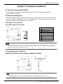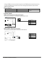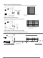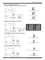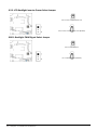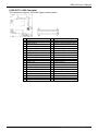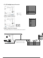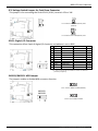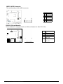
1
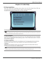
FCC Information and Copyright
This equipment has been tested and found to comply with the limits of a Class B digital device,
pursuant to Part 15 of the FCC Rules. These limits are designed to provide reasonable protection
against harmful interference in a residential installation. This equipment generates, uses, and can
radiate radio frequency energy and, if not installed and used in accordance with the instructions,
may cause harmful interference to radio communications. There is no guarantee that
interference will not occur in a particular installation.
The vendor makes no representations or warranties with respect to the contents here and
specially disclaims any implied warranties of merchantability or fitness for any purpose. Further
the vendor reserves the right to revise this publication and to make changes to the contents
here without obligation to notify any party beforehand.
Duplication of this publication, in part or in whole, is not allowed without first obtaining
the vendor’s approval in writing.
The content of this user’s manual is subject to be changed without notice and we will not be
responsible for any mistakes found in this user’s manual. All the brand and product names
are trademarks of their respective companies.
Dichiarazione di conformità sintetica
Ai sensi dell’art. 2 comma 3 del D.M. 275
del 30/10/2002
Si dichiara che questo prodotto è
conforme alle normative vigenti e soddisfa
i requisiti essenziali richiesti dalle direttive
2004/108/CE, 2006/95/CE e
1999/05/CE quando ad esso applicabili
Short Declaration of conformity
We declare this product is complying with the
laws in force and meeting all the essential
requirements as specified by the directives
2004/108/CE, 2006/95/CE and 1999/05/CE
whenever these laws may be applied
Table Of Contents
FCC Information and Copyright ������������������������������������������������������������������������������� 1 Chapter 1:
Introduction ������������������������������������������������������������������������������������������� 3
1.1 Before You Start ������������������� ��������� �������� ��������� ��������� �������� ��������� ��������� ��������� �� ��������� ���� �������� �� 3
1.2 Package Checklist ���������������������� �������� ��������� ��������� ��������� �������� ��������� ��������� ������� ���������� ��� �������� � 3
1.3 Specifications ���� �������� ��������� ��������� ��������� �������� ��������� ��������� �������� ��������� ��������� �� ������� ������ �������� ���� 4
Chapter 2: Hardware installation ����������������������������������������������������������������������������� 9
2.1 Central Processing Unit (CPU) ��������������������������������������������������������������������������������������������� 9
2.2 Connect Cooling Fans ������������������ ��������� ��������� ��������� �������� ��������� ��������� �������� ��������� ������������ � ���� 9
2.3 Installing System Memory �������������������������������������������������������������������������������������������������� 9
2.4 Power Supply ����������������� �������� ��������� ��������� �������� ��������� ��������� ��������� �������� ������ �������� ����� �������� ��� 10
2.5 Jumpers / Headers / Connectors �������������������������������������������������������������������������������������� 11
2.6 Expansion Slots ���������������������� �������� ��������� ��������� �������� ��������� ��������� ��������� �������� ��������� ���� �������� � 18
Chapter 3: BIOS Setup ������������������������������������������������������������������������������������������� 19
3.1 Main Menu ����������������������� ��������� �������� ��������� ��������� ��������� �������� ��������� ��������� � ������ ������� �������� ���� 20
3.2 Advanced Menu ������������������������� ��������� ��������� �������� ��������� ��������� �������� ��������� ����� ��������� ���� �������� 21
3.3 Chipset Menu ������������������������� ��������� ��������� �������� ��������� ��������� ��������� �������� ������ �������� ����� �������� �� 34
3.4 Security Menu ����������������������� �������� ��������� ��������� �������� ��������� ��������� ��������� �������� �������� ����� �������� � 40
3.5 Boot Menu ������������������������ ��������� ��������� �������� ��������� ��������� ��������� �������� ��������� ������ ������� �������� ����� 42
3.6 Exit Menu ������������������������� ��������� �������� ��������� ��������� �������� ��������� ��������� �������� ������ ������� �������� ������� 43
Chapter 4: Useful help ������������������������������������������������������������������������������������������ 44
4.1 Driver Insta lla tion ��������� �������� ��������� ��������� �������� ��������� ��������� �������� ��������� ��������� ���� ��������� ���� ����� 44
4.2 AMI BIOS Beep Code ������������������������� ��������� �������� ��������� ��������� �������� ��������� ��������� ��� ����������� �� �� 45
4.3 AMI BIOS post code ������������������������� �������� ��������� ��������� �������� ��������� ��������� �������� ���� ����������� �� ���� 45
4.4 Troubles hooting ��������� ��������� ��������� �������� ��������� ��������� �������� ��������� ��������� �������� ����� �������� ����� ������� 47
2 | Table Of Contents
BIBD-ICP User’s Manual
Chapter 1: Introduction
1.1 Before You Start
Thank you for choosing our product. Before you start installing the motherboard, please
make sure you follow the instructions below:
••• Prepare a dry and stable working environment with sufficient lighting.
••• Always disconnect the computer from power outlet before operation.
••• Before you take the motherboard out from anti-static bag, ground yourself properly
by touching any safely grounded appliance, or use grounded wrist strap to remove the
static charge.
••• Avoid touching the components on motherboard or the rear side of the board
unless necessary. Hold the board on the edge, do not try to bend or flex the board.
••• Do not leave any unfastened small parts inside the case after installation. Loose
parts will cause short circuits which may damage the equipment.
••• Keep the computer from dangerous area, such as heat source, humid air and water.
••• The operating temperatures of the computer should be 0 to 45 degrees Celsius.
••• To avoid injury, be careful of:
Sharp pins on headers and connectors
Rough edges and sharp corners on the chassis
Damage to wires that could cause a short circuit
1.2 Package Checklist
••• Mini-ITX Mainboard x 1
••• Fully Setup Driver DVD x 1
••• I/O Bracket x 1
••• SATA Cable x 1
Note
»»» The package contents may be different due to the sales region or models in which it was sold.
For more information about the standard package in your region, please contact your dealer or
sales representative.
Chapter 1: Introduction | 3
1.3 Specifications
CPU
Intel Celerin J1900(2.0GHz@10W) 4T/4C 2M L2 cache
Integrated Intel® HD Graphics series graphic engine supports:
Graphics Frequency: Intel Graphics HD 321MHz-750MHz
Graphic
Dual independent displays (Extended mode) as below two:
-- Integrated VGA D-Sub
-- Integrated LVDS dual channel 18-24Bits support by RTD2136R Realtek
FINTEK F81866AD
Super I/O
Provides the most commonly used legacy Super I/O functionality. 128pin type
Environment Control initiatives, H/W Monitor, Fan Speed Controller
2x SO-DIMM (204pin) slot, DDR3L 1333/1066 MHz, Max 8GB
Main Memory
Registered DIMM or ECC DIMM is not supported
* DIMMB1 slot is optional.
Chipset built-in Serial ATA controller
SATA
LAN
Sound Codec
Expansion Slots
SATA Version 2.0 specification compliant
Data transfer rates up to 3.0 Gb/s
Realtek RTL 8111G
10 / 100 / 1000 Mb/s auto negotiation, Half / Full duplex capability
Realtek Codec ALC662, supports Line-out/Mic-in
1x Mini PCI-E slot (Height @ 8mm), Mini PCI-E or mSATA function can be selected by BIOS
1x 2x2 Pin DC Jack
1x DC jack (RJ11), 12V/24V input select by jumper
1x VGA D-Sub
4x USB 2.0
Back Panel I/O
1x RJ-45 (Gigabit LAN)
1x PS2 for KB/Mouse
3x COM
- COM1 (RS232/422/485) support RI/5V/2V power select
- COM2/3 (RS232), support RI/5/12V power select
1x Audio Connectors (for Line-out/MIC-in)
4 | Chapter 1: Introduction
BIBD-ICP User’s Manual
SATA
2x SATA II up to 3Gb/s HDD connector (SATA2 is shared with mini PCI-E slot)
Display
1x 2*20 pins, LCD LVDS connector support Dual Channel
1x 1*8 pins, LCD Backlight Inverter power connector
1x 1*3 pins, LCD Backlight power select jumper(3.3V/5V)
1x 1*3 pins, LCD Inverter power select jumper(5V/12V)
1x 1*3 pins, Backlight control mode select jumper
1x 1*3 pins, Backlight PWM signal select jumper
Speaker
2x 1*2 pins for Amplifier output ALC105 class D 3Watt/Channel Amplifier
1x buzzer
On Board Connectors
& Headers
Power
1x 2*2 pins + 12V DC-in connector(Share with rear DC Jack)
2x 1*4 pins for HDD power 5V
I/O
1x 2*5 pins, USB2.0 pin header support 2 USB devices
1x 2*5 pins, USB3.0 pin header support 1 USB device
4x 2*5 pins COM3/4/5/6, RS232, support Ring/5/12V 2*3 pins power select
1x 2*5 pins header, digital IO support 4 in 4 out
1x 2*13 pins, parallel header for printer
2x 1*3 pins, system fan and CPU smart fan header
1x 2*5 pins front panel as Power/Reset/HDD/LAN header
1x 1*6 pins box header, internal cash drawer
1 x 1*6 pins MSR pin header
2 x 1*3 pins jumper, MSR definition change
Board Size
Operation Temperature
Storage Temperature
Relative Humidity
1 x 1*6 pins header, SIM card
170 mm (W) x 170 mm (L), Mini-ITX
0°C ~ 60°C
-20°C ~ 80°C
10% ~ 90% (non-condensing)
Win 7, Win 8, POSReady, Linux Fedora 14, Intel® Embedded Graphics Drivers Version 10 (Support by Intel
OS Support
EIA IEGD tools)
Biostar reserves the right to add or remove support for any OS with or without notice.
Chapter 1: Introduction | 5
1.4 Rear Panel Connectors
JP2: DC-12V Input Connector
Pin
1
2
3
4
Assignment
+12V DC_IN
+12V DC_IN
GND
GND
COM1 Serial Port Connectors
Pin
1
2
3
4
5
6
7
8
9
Assignment
Carrier detect (DCD)
Received data (RXD)
Transmitted data (TXD)
Data terminal ready (DTR)
Signal ground (GND)
Data set ready (DSR)
Request to send (RTS)
Clear to send (CTS)
Ring / 5V / 12V *
(selected by BIOS setting)
COM2/3 Serial Port Connectors (RS232)
Pin
1
2
3
4
5
6 | Chapter 1: Introduction
Assignment
Carrier detect (DCD)
Received data (RXD)
Transmitted data (TXD)
Data terminal ready (DTR)
Signal ground (GND)
Pin
6
7
8
9
Assignment
Data set ready (DSR)
Request to send (RTS)
Clear to send (CTS)
Ring / 5V / 12V *
BIBD-ICP User’s Manual
JPC3: COM3 Serial Port Voltage Switch Jumper
2
1
Pin 1-2 Close: Pin9=Ring
4
3
Pin 3-4 Close: Pin9= 5V
6
5
Pin 5-6 Close: Pin9=12V
Note
»»» Note1: COM1/2 voltage selection is controlled by BIOS setup. Please see page-23 & 24 for detail
setting.
RJ-11 pin define
Pin
1
2
3
4
5
6
Define
CASE OPEN2_N
CASH1 _P
CASE OPEN_N
CASH_PWR (12/24V)
CASH2_P
GND
Function
Status Pin
Control Pin
Status Pin
--Control Pin
---
GPIO
S5_25
S0_82
S5_24
--S0_83
---
address (memory space)
0XFED0E1B8 bit0
0XFED0C1D8 bit0
0XFED0E1C8 bit0
--0XFED0C1B8 bit0
---
»»» You could read the address value at dword (32 bits/4 bytes).
Chapter 1: Introduction | 7
1.5 Motherboard Layout
BUZZ1
VGA1
COM3
JPC3
JHDD1
JHDD2
COMA1
COM2
COM1
JUSB1
CPU_FAN1
JCOMS1
JCOM4
JCOM5
JCOM6
JMSRS1 JMSR1
JMSRS2
JPC4
F_USB1
JPC5
JBLR1
JLV3
JLV2
Note
»»» represents the 1st pin.
»»» DIMMB1 slot is optional.
8 | Chapter 1: Introduction
JLV1
JPC6
JC1
SYS_FAN1
JSIM1
BIBD-ICP User’s Manual
Chapter 2: Hardware installation
2.1 Central Processing Unit (CPU)
The mainboard includes an onboard Intel® SOC, and a cooler has been installed to
provide sufficient cooling.
2.2 Connect Cooling Fans
These fan headers support cooling-fans built in the computer. The fan cable and connector
may be different according to the fan manufacturer. Connect the fan cable to the
connector while matching the black wire to pin#1.
CPU_FAN1: CPU fan header
SYS_FAN1: System fan header
CPU_FAN1
SYS_FAN1
JCFAN1
Pin Assignment
1
Ground
2
Smart Fan Control
3
FAN RPM rate sense
JSFAN1
Pin Assignment
1
Ground
2
+12V
3
FAN RPM rate sense
Note
»»» System Fan Headers support 3-pin head connectors. When connecting with wires onto connectors,
please note that the red wire is the positive and should be connected to pin#2, and the black wire is
Ground and should be connected to GND.
2.3 Installing System Memory
DIMMA1/B1: DDR3L Memory Module (204pin SO-DIMM)
Note
»»» The DIMM must be installed to DIMMA1 slot first. The DIMMB1 slot is optional.
»»» If the DIMM does not go in smoothly, do not force it. Pull it all the way out and try again.
Chapter 2: Hardware installation | 9
1. Align a DIMM on the slot such that the notch on the DIMM matches the break on the slot.
2. Insert the DIMM firmly into the slot until the retaining clips snap back in place and the
DIMM is properly seated.
Memory Capacity
DIMM Socket Location
DIMMA1
DDR3 Module
512MB/1GB/2GB/4GB
DIMMB1
512MB/1GB/2GB/4GB
Total Memory Size
Max is 8GB
2.4 Power Supply
JPWR1: ATX Power Source Connector (4-pin)
This connector provides or +12V input to system power circuit.
Pin
Assignment
1
2
+12V in
+12V in
3
Ground
4
Ground
JHDD1/JHDD2: HDD Power Connector
This connector provides power connection of SATA devices.
Pin Assignment
1
+12V output
JHDD1
JHDD2
10 | Chapter 2: Hardware installation
2
GND
3
GND
4
+5V output
BIBD-ICP User’s Manual
2.5 Jumpers / Headers / Connectors
Jumper Setting
The illustration shows how to set up jumpers. When the jumper cap is placed on pins,
the jumper is “close”, if not, that means the jumper is “open”.
Pin opened
Pin closed
Pin 1-2 closed
JCMOS1: Clear CMOS Jumper
Placing the jumper on pin2-3 allows user to restore the BIOS safe setting and the CMOS data.
Please carefully follow the procedures to avoid damaging the motherboard.
1
3
Pin 1-2 Close: Normal Operation (Default)
1
3
Pin 2-3 Close: Clear CMOS data
Clear CMOS Procedures:
1. Remove AC power line.
2. Set the jumper to “Pin 2-3 close”.
3. Wait for five seconds.
4. Set the jumper to “Pin 1-2 close”.
5. Power on the AC.
6. Reset your desired password or clear the CMOS data.
JPANEL1: Front Panel Header
This 10-pin header includes Power-on, Reset, HDD LED, and Power LED connection. It
allows user to connect the system case’s front panel switch functions.
Function Pin Assignment
N/A
1
Key
3
HD LED+
5
HD LED-
Reset
7
Reset GND
Button
9
Reset
HDD
LED
Function Pin Assignment
2
Power LED+
Power
4
Power LED+
LED
6
Power LED-
Power
8
Power
Button
10
Power GND
Chapter 2: Hardware installation | 11
SATA1/2: Serial ATA 3.0 Gb/s Connectors
These connectors support the thin Serial ATA cable for primary internal storage devices.
Pin Assignment
1
Ground
2
TX+
3
TX-
4
Ground
5
RX-
6
RX+
7
Ground
»»» SATA2 is optional and shared with Mini
PCI-E slot.
JUSB1: USB 3.0 Vertical Connector
This connector allows you to connect one USB 3.0 port.
Pin Assignment
1
RX-
Pin
2
Assignment
VCC
3
RX+
4
VCC
5
GND
6
GND
7
TX+
8
D+
9
TX-
10
D-
»»» This USB 3.0 connector is not
backward compatible with
USB 2.0 devices.
F_USB1: Header for USB 2.0 Ports at Front Panel
This header allows you to connect two additional USB 2.0 ports.
9
1
+5V (fused)
2
+5V (fused)
3
USB -
4
USB -
5
USB +
6
USB +
Key
10
NC
12 | Chapter 2: Hardware installation
BIBD-ICP User’s Manual
Serial Port Connectors & Headers
JPC4/5/6: JCOM4/5/6 Serial Port Voltage Switch Jumper
2
1
Pin 1-2 Close: Pin9=Ring (Default)
4
3
Pin 3-4 Close: Pin9= 5V
6
2
6
5
1
5
Pin 5-6 Close: Pin9=12V
JCOM4/JCOM5/JCOM6: Serial Port Headers
JCOM4 JCOM5
2
1
JCOM6
10
9
Pin
1
3
5
7
9
Assignment
-PDCD
PSOUT data
GND
-PRTS
Ring/ 5V / 12V*
Pin
2
4
6
8
10
Assignment
PSIN
-PDTR
-PDSR
-PCTS
NA
JLV1: Backlight Control Mode Selection Jumper
Pin 1-2 Closed: Voltage Level Mode
Pin 2-3 Closed: PWM Mode (Default)
JLV2: LCD Panel Power Select Jumper
Pin 1-2 Close: Inverter Power=3.3V (Default)
Pin 2-3 Close: Inverter Power=5V
Chapter 2: Hardware installation | 13
JLV3: LCD Backlight Inverter Power Select Jumper
Pin 1-2 Close: Inverter Power=5V
Pin 2-3 Close: Inverter Power=12V (Default)
JBLR1: Backlight PWM Signal Select Jumper
Pin 1-2 Close: Reverse
Pin 2-3 Close: Forward (Default)
14 | Chapter 2: Hardware installation
BIBD-ICP User’s Manual
LVDS-OUT1: LVDS Connector
This connector supports 18/24 bit single-channel panels.
40
2
39
Pin
1
3
5
7
9
11
13
15
17
19
21
23
25
27
29
31
33
35
37
39
Assignment
LVDSB_DATA0_N
LVDSB_DATA0_P
GND
LVDSB_DATA1_N
LVDSB_DATA1_P
GND
LVDSB_DATA2_N
LVDSB_DATA2_P
GND
LVDSB_CLK_N
LVDSB_CLK_P
GND
LVDSB_DATA3_N
LVDSB_DATA3_P
VCC5
LVDSA_DDC_CLK
VCC3_3
NC
PVDD2, 3.3V/5V (selected by JLV2)
PVDD2, 3.3V/5V (selected by JLV2)
1
Pin
2
4
6
8
10
12
14
16
18
20
22
24
26
28
30
32
34
36
38
40
Assignment
PVDD2, 3.3V/5V (selected by JLV2)
PVDD2, 3.3V/5V (selected by JLV2)
GND
GND
LVDSA_DATA0_N
LVDSA_DATA0_P
GND
LVDSA_DATA1_N
LVDSA_DATA1_P
GND
LVDSA_DATA2_N
LVDSA_DATA2_P
GND
LVDSA_CLK_N
LVDSA_CLK_P
GND
LVDSA_DATA3_N
LVDSA_DATA3_P
NC
LVDSA_DCC_DATA
Chapter 2: Hardware installation | 15
JC1: LCD Backlight Inverter Connector
Pin
1
2
3
4
5
6
7
8
Assignment
5V/12V*
5V/12V*
NC
NC
Backlight On(5V)/Off(0V)
Brightness Adjust (0-5V)
GND
GND
* selected by JLV3
JSPK1/2: Audio Connector
RightSpeaker (JSPK1)
Pin Assignment
1
SPKRN
2
SPKRP
Left Speaker (JSPK2)
Pin Assignment
1
SPKLN
2
SPKLP
JPRNT1: Printer Port Connector
This header allows you to connect printer port on the PC.
1
3
17
Data 7
18
Ground
19
-ACK
20
Ground
21
23
25
Busy
PE
SCLT
22
24
26
Ground
Ground
Key
5
7
9
Data 1
Data 2
Data 3
11
Data 4
13
Data 5
16 | Chapter 2: Hardware installation
BIBD-ICP User’s Manual
JP1: Voltage Switch Jumper for Cash Draw Connector
This jumper is for controlling the Pin4 of RJ11 (JRJ11) to switch 12V or 24V.
Pin 1-2 Close: Pin4 of RJ11(JRJ11)=24V
(Default)
Pin 2-3 Close: Pin4 of RJ11(JRJ11)=12V
JDIO1: Digital I/O Connector
This connector offers 4-pair of digital I/O functions and address is set in BIOS.
2
10
1
9
Pin
1
2
3
4
5
6
7
8
9
10
Assignment
5V
DI-01
DO-01
DI-02
DO-02
DI-03
DO-03
DI-04
DO-04
GND
address(I/O space)
-528H bit23
-528H bit27
-548H bit28
-548H bit29
---
address(memory space)
--0XFED0E348 bit 0
-0XFED0E218 bit 0
-0XFED0E168 bit 0
-0XFED0E158 bit 0
--
GPIO
-S0_55
S5_40
S0_59
S5_1
S0_92
S5_26
S0_93
S5_27
--
»»» You could read the address value at dword
(32 bits/4 bytes).
JMSRS1/JMSRS2: MSR Jumper
The jumpers enable or disable MSR connector function.
1
3
Pin 1-2 Close: JMSR1 Disabled (Default)
JMSRS1
JMSRS2
1
3
Pin 2-3 Close: JMSR1 Enabled
Chapter 2: Hardware installation | 17
JMSR1: MSR Connector
The mainboard provides MSR connector.
1
Pin
1
2
3
4
5
6
6
Assignment
PS2CLK
PS2DAT
KCLK
KDAT
GND
+5V
JSIM1: SIM card header
This mainboard is equipped with one SIM card header for Mini PCI-E Slot.
1
18 | Chapter 2: Hardware installation
6
Pin
Assignment
1
GND
2
3
UIM_RESET
UIM_CLK
4
UIM_DATA
5
UIM_VPP
6
UIM_PWR
BIBD-ICP User’s Manual
2.6 Expansion Slots
PE1: Mini PCI-E Slot (Height @ 8mm)
This mainboard is equipped with 1 Mini PCI-E Slots.
Install an Expansion Card
You can install your expansion card by following steps:
••• Read the related expansion card’s instruction document before install the
expansion card into the computer.
••• Remove your computer’s chassis cover, screws and slot bracket from the computer.
••• Place a card in the expansion slot and press down on the card until it is
completely seated in the slot.
••• Secure the card’s metal bracket to the chassis back panel with a screw.
••• Replace your computer’s chassis cover.
••• Power on the computer, if necessary, change BIOS settings for the expansion card.
••• Install related driver for the expansion card.
Chapter 2: Hardware installation | 19
Chapter 3: BIOS Setup
Introduction
The purpose of this manual is to describe the settings in the AMI UEFI BIOS Setup program
on this motherboard. The Setup program allows users to modify the basic system
configuration and save these settings to NVRAM.
UEFI BIOS determines what a computer can do without accessing programs from a disk. This
system controls most of the input and output devices such as keyboard, mouse, serial ports
and disk drives. BIOS activates at the first stage of the booting process, loading and
executing the operating system. Some additional features, such as virus and password
protection or chipset fine-tuning options are also included in UEFI BIOS.
The rest of this manual will to guide you through the options and settings in UEFI BIOS Setup.
Plug and Play Support
This AMI UEFI BIOS supports the Plug and Play Version 1.0A specification.
EPA Green PC Support
This AMI UEFI BIOS supports Version 1.03 of the EPA Green PC specification.
ACPI Support
AMI ACPI UEFI BIOS support Version 1.0/2.0 of Advanced Configuration and Power interface
specification (ACPI). It provides ASL code for power management and device configuration
capabilities as defined in the ACPI specification, developed by Microsoft, Intel and Toshiba.
PCI Bus Support
This AMI UEFI BIOS also supports Version 2.3 of the Intel PCI (Peripheral Component
Interconnect) local bus specification.
DRAM Support
DDR3 SDRAM (Double Data Rate III Synchronous DRAM) is supported.
Supported CPUs
This AMI UEFI BIOS supports the latest CPU.
Using Setup
When starting up the computer, press <Del> during the Power-On Self-Test (POST) to enter
the UEFI BIOS setup utility. In the UEFI BIOS setup utility, you will see General Help
description at the top right corner, and this is providing a brief description of the selected
item. Navigation Keys for that particular menu are at the bottom right corner, and you can
use these keys to select item and change the settings.
Note
»»» The default UEFI BIOS settings apply for most conditions to ensure optimum performance of the
motherboard. If the system becomes unstable after changing any settings, please load the default
settings to ensure system’s compatibility and stability. Use Load Setup Default under the Exit Menu.
»»» For better system performance, the UEFI BIOS firmware is being continuously updated. The
UEFI BIOS information described in this manual is for your reference only. The actual UEFI BIOS
information and settings on board may be slightly different from this manual.
»»» The content of this manual is subject to be changed without notice. We will not be responsible
for any mistakes found in this user’s manual and any system damage that may be caused by
wrong-settings.
20 | Chapter 3: BIOS Setup
BIBD-ICP User’s Manual
3.1 Main Menu
Once you enter AMI UEFI BIOS Setup Utility, the Main Menu will appear on the
screen providing an overview of the basic system information.
BIOS Information
Shows system information including UEFI BIOS version, model name, marketing name,
built date, etc.
Memory Frequency
Shows the system memory frequency.
Total Memory
Shows system memory size, VGA shard memory will be excluded.
System Date
Set the system date. Note that the ‘Day’ automatically changes when you set the date.
System Time
Set the system internal clock.
Access Level
Shows the access level of current user.
Chapter 3: BIOS Setup | 21
3.2 Advanced Menu
The Advanced Menu allows you to configure the settings of CPU, Super I/O, Power
Management, and other system devices.
Note
»»» Beware of that setting inappropriate values in items of this menu may cause system to malfunction.
»»» The options and default settings might be different by RAM or CPU models.
ACPI Settings
Enable ACPI Auto Configuration
This item enables or disables BIOS ACPI Auto
Configuration. Options: Disabled (Default) / Enabled
Enable Hibernation
This item enables or disables system ability to hibernate (OS/S4 sleep state)/ This option
may be not effective with some OS.
Options: Enabled (Default) / Disabled
22 | Chapter 3: BIOS Setup
BIBD-ICP User’s Manual
ACPI Sleep State
This item selects the highest ACPI sleep state the system will enter when the SUSPEND
button is pressed.
Options: S3 (Suspend to RAM)(Default) / Suspend Disabled
Lock Legacy Resources
This item enables or disables Lock of Legacy
Resources. Options: Disabled (Default) / Enabled
Restore AC Power Loss
This item enables the system to wake from S5 using Ring-In
event. Options: Power Off (Default) / Power On / Last State
EuP Control
When EuP is enabled, the system will meet EuP requirement.
Options: Disabled (Default) / Enabled
PME Wake up from S5
This item enables the system to wake from S5 using PEM event.
Options: Disabled (Default) / Enabled
Wake system with Fixed Time
This item enables or disables the system to wake on by alarm event. When this item is
enabled, the system will wake on the hr::min::sec specified.
Options: Disabled (Default) / Enabled
Wake up date
You can choose which date the system will boot up.
Wake up hour / Wake up minute / Wake up second
You can choose the system boot up time, input hour, minute and second to specify.
USB Device Wakeup from S3/S4
This item allows you to enable or disabled the USB resume from S3/S4
function. Options: Disabled (Default) / Enabled
Ring-In Wake up from S5
This item enables the system to wake from S5 using Ring-In
event. Options: Disabled (Default) / Enabled
PS2 Keyboard PowerOn
This item allows you to control the keyboard power on function.
Options: Disabled (Default) / Ctrl + Esc / Ctrl + F1 / Ctrl + Space / Any key / Wake Key / Power
Key / Ctrl + Alt + Space / Space
PS2 Mouse PowerOn
This item allows you to control the mouse power on
function. Options: Disabled (Default) / Enabled
Chapter 3: BIOS Setup | 23
Super IO Configuration
Serial Port 1 Configuration
Serial Port
This item enables or disables Serial Port (COM).
Options: Enabled (Default) / Disabled
Change Settings
This item selects an optimal setting for Super IO device.
Options: Auto (Default) / IO=3F8h; IRQ=4 / IO=3F8h; IRQ= 3,4,5,6,7,9,10,11,12 / IO=2F8h; IRQ=
3,4,5,6,7,9,10,11,12 / IO=3E8h; IRQ= 3,4,5,6,7,9,10,11,12 / IO=2E8h; IRQ= 3,4,5,6,7,9,10,11,12
Serial Port 1 Power
This item sets serial port 1 power.
Options: Ring / 5V / 12V (Default)
24 | Chapter 3: BIOS Setup
BIBD-ICP User’s Manual
Serial Port 2 Configuration
Serial Port
This item enables or disables Serial Port (COM).
Options: Enabled (Default) / Disabled
Change Settings
This item selects an optimal setting for Super IO device.
Options: Auto (Default) / IO=2F8h; IRQ=3 / IO=3F8h; IRQ= 3,4,5,6,7,9,10,11,12 / IO=2F8h; IRQ=
3,4,5,6,7,9,10,11,12 / IO=3E8h; IRQ= 3,4,5,6,7,9,10,11,12 / IO=2E8h; IRQ= 3,4,5,6,7,9,10,11,12
Serial Port 2 Power
This item sets serial port 1 power.
Options: Ring / 5V (Default) / 12V
Serial Port 3 Configuration
Serial Port
This item enables or disables Serial Port (COM).
Options: Enabled (Default) / Disabled
Chapter 3: BIOS Setup | 25
Change Settings
This item selects an optimal setting for Super IO device.
Options: Auto (Default) / IO=2C0h; IRQ=6 / IO=2C0h; IRQ= 3,4,5,6,7,9,10,11,12 / IO=2C8h; IRQ=
3,4,5,6,7,9,10,11,12 / IO=2D0h; IRQ= 3,4,5,6,7,9,10,11,12 / IO=2D8h; IRQ= 3,4,5,6,7,9,10,11,12
Serial Port 4 Configuration
Serial Port
This item enables or disables Serial Port (COM).
Options: Enabled (Default) / Disabled
Change Settings
This item selects an optimal setting for Super IO device.
Options: Auto (Default) / IO=2C8h; IRQ=6 / IO=2C0h; IRQ= 3,4,5,6,7,9,10,11,12 / IO=2C8h; IRQ=
3,4,5,6,7,9,10,11,12 / IO=2D0h; IRQ= 3,4,5,6,7,9,10,11,12 / IO=2D8h; IRQ= 3,4,5,6,7,9,10,11,12
Serial Port 5 Configuration
Serial Port
This item enables or disables Serial Port (COM).
Options: Enabled (Default) / Disabled
26 | Chapter 3: BIOS Setup
BIBD-ICP User’s Manual
Change Settings
This item selects an optimal setting for Super IO device.
Options: Auto (Default) / IO=2D0h; IRQ=6 / IO=2C0h; IRQ= 3,4,5,6,7,9,10,11,12 / IO=2C8h; IRQ=
3,4,5,6,7,9,10,11,12 / IO=2D0h; IRQ= 3,4,5,6,7,9,10,11,12 / IO=2D8h; IRQ= 3,4,5,6,7,9,10,11,12
Serial Port 6 Configuration
Serial Port
This item enables or disables Serial Port (COM).
Options: Enabled (Default) / Disabled
Change Settings
This item selects an optimal setting for Super IO device.
Options: Auto (Default) / IO=2D8h; IRQ=6 / IO=2C0h; IRQ= 3,4,5,6,7,9,10,11,12 / IO=2C8h; IRQ=
3,4,5,6,7,9,10,11,12 / IO=2D0h; IRQ= 3,4,5,6,7,9,10,11,12 / IO=2D8h; IRQ= 3,4,5,6,7,9,10,11,12
Parallel Port Configuration
Parallel Port
This item enables or disables Parallel Port (LPT/LPTE).
Options: Enabled (Default) / Disabled
Chapter 3: BIOS Setup | 27
Change Settings
This item allows you to select an optimal setting for Super IO device.
Options: Auto (Default) / IO=378h; IRQ=7 / IO=378h; IRQ=5,6,7,9,10,11,12 / IO=278h;
IRQ=5,6,7,9,10,11,12 / IO=3BCh; IRQ=5,6,7,9,10,11,12
UART IRQ Mode
This item sets PCI IRQ Sharing for OS(EX. Windows) or ISA IRQ for Dos.
Options: PCI IRQ Sharing (Default) / ISA IRQ
Watch Dog Degree
This item allows you to determine the functional degree of Watch Dog.
Options: Second (Default) / Minute
Watch Dog Timer
Options: 0 for disabled (Default) / Min=1, Max=255
H/W Monitor
Smart Fan Function
This item allows you to control the CPU Smart Fan function.
Options: Enabled (Default)/ Disabled
28 | Chapter 3: BIOS Setup
BIBD-ICP User’s Manual
Smart Fan Mode Configuration
CPU_Fan 1 Smart Fan Control
This item selects Smart Fan Mode.
Options: Manual RPM Mode (Default) / Manual Duty Mode / Auto RPM Mode / Auto
Duty_ cycle Mode
CPU Configuration
Active Processor Cores
This item sets number of cores to enable in each processor package.
Options: All (Default) / 1
Limit CPUID Maximum
When the computer is booted up, the operating system executes the CPUID instruction to
identify the processor and its capabilities. Before it can do so, it must first query the
processor to find out the highest input value CPUID recognizes. This determines the kind of
basic information CPUID can provide the operating system.
Options: Disabled (Default) / Enabled
Chapter 3: BIOS Setup | 29
Execute-Disable Bit
XD can prevent certain classes of malicious buffer overflow attacks when combined with a
supporting OS (Windows Server 2003 SP1, Windows XP SP2, SuSE Linux 9.2, RedHat Enterprise
3 Update 3.).
Options: Enabled (Default) / Disabled
Hardware Prefetcher
The processor has a hardware prefetcher that automatically analyzes its requirements and
prefetches data and instructions from the memory into the Level 2 cache that are likely to
be required in the near future. This reduces the latency associated with memory reads.
Options: Enabled (Default) / Disabled
Adjacent Cache Line Prefetch
The processor has a hardware adjacent cache line prefetch mechanism that
automatically fetches an extra 64-byte cache line whenever the processor requests for a
64-byte cache line. This reduces cache latency by making the next cache line immediately
available if the processor requires it as well.
Options: Enabled (Default) / Disabled
Intel Virtualization Technology
Virtualization Technology can virtually separate your system resource into several parts,
thus enhance the performance when running virtual machines or multi interface systems.
Options: Enabled (Default) / Disabled
Power Technology
This item enables or disables the power management features.
Options: Custom (Default) / Disable / Energy Efficient
EIST
This item enables or disables Intel SpeedSteps.
Options: Enabled (Default) / Disabled
Turbo Mode
This item enables or disables Turbo Mode.
Options: Enabled (Default) / Disabled
P-STATE Coordination
This item changes P-STATE Coordination. Options:
HW_ALL (Default) / SW_ALL / SW_ANY
CPU C6 Report
This item enables or disables CPU C6 (ACPI C3) report to OS.
Options: Enabled (Default) / Disabled
CPU C7 Report
This item enables or disables CPU C7 (ACPI C3) report to OS.
Options: Enabled (Default) / Disabled
Package C state limit
This item enables or disables package C state limit.
Options: No Limit (Default) / CO / C1 / C3 / C6 / C7
30 | Chapter 3: BIOS Setup
BIBD-ICP User’s Manual
PPM Configuration
EIST
This item enables or disables Intel SpeedSteps.
Options: Enabled (Default) / Disabled
CPU C state Report
This item enables or disables CPU C state report to OS.
Options: Enabled (Default) / Disabled
Enhanced C state
This item enables or disables Enhanced CPU C state.
Options: Enabled (Default) / Disabled
Max CPU C-state
This option controlls Max C state that the processor will support.
Options: C7 (Default) / C6 / C1
SATA Configuration
Chapter 3: BIOS Setup | 31
Serial-ATA (SATA)
This item enables/disables Serial ATA Device.
Options: Enabled (Default) / Disabled
SATA ODD Port
This item selects SATA ODD Port
Options: No ODD (Default) / Port0 ODD / Port1 ODD
SATA Mode
This item determines how SATA controller(s) operate.
Options: IDE (Default) / AHCI
Serial-ATA Port 1/2
This item enables/disables Serial ATA Port 1/2
Options: Enabled (Default) / Disabled
SMART Self Test
Run SMART Self Test on all HDDs during POST.
Options: Disabled (Default) / Enabled
Network Stack
Network Stack
This item enables or disables UEFI network stack
Options: Disabled (Default) / Enabled
»»» Note: The following items appear only when you set the Network Stack to [Enabled]
IPv4 PXE Support
This item enables or disables IPv4 PXE Boot Support. If disabled IPv4 booth option will not
be created.
Options: Enabled (Default) / Disabled
IPv6 PXE Support
This item enables or disables IPv6 PXE Boot Support. If disabled IPv6 booth option will not
be created.
Options: Enabled (Default) / Disabled
PXE boot wait time
Wait time to press ESC key to abort the PXE boot.
32 | Chapter 3: BIOS Setup
BIBD-ICP User’s Manual
CSM Configuration
CSM Support
This item enables or disables CSM Support
Options: Enabled (Default) / Disabled
GateA20 Active
Upon Request – FA20 can be disabled using BIOS services. Always – do not allow disabling
GA20; this option is useful when any RT code is executed above
1MB Options: Upon Request (Default) / Always
Option ROM Messages
This item sets the display mode for option ROM.
Options: Force BIOS (Default) / Keep Current
INT19 Trap Response
BIOS reaction on INT19 trapping by Option ROM: IMMEDIATE – execute the trap right away;
POSTPONED – execute the trap during legacy boot.
Options: Immediate (Default) / Postponed
Boot option filter
This option controls what devices system can boot to. Options:
Legacy only (Default) / UEFI and Legacy / UEFI only
Network
This option controls the execution of UEFI and Legacy PXE OpROM
Options: Legacy only (Default) / Do not launch / UEFI only / Legacy first / UEFI first
Storage
This option controls the execution of UEFI and Legacy Storage OpROM
Options: Legacy only (Default) / Do not launch / UEFI only / Legacy first / UEFI first
Video
This option controls the execution of UEFI and Legacy Video OpROM
Options: Legacy only (Default) / Do not launch / UEFI only / Legacy first / UEFI first
Other PCI devices
For PCI devices other than Network, Mass storage or video defines which OpROM to
launch. Options: Legacy only (Default) / UEFI first
Chapter 3: BIOS Setup | 33
USB Configuration
Legacy USB Support
This item determines if the BIOS should provide legacy support for USB devices like the
keyboard, mouse, and USB drive. This is a useful feature when using such USB devices
with operating systems that do not natively support USB (e.g. Microsoft DOS or Windows
NT). Options: Enabled (Default) / Disabled / Auto
XHCI Hand-Off
This is a workaround for OSes without XHCI hand-off support. The XHCI ownership
change should be claimed by XHCI driver.
Options: Enabled (Default) / Disabled
EHCI Hand-Off
This is a workaround for OSes without EHCI hand-off support. The EHCI ownership
change should be claimed by EHCI driver.
Options: Disabled (Default) / Enabled
USB Mass Storage Driver Support
The item allows you to enable or disable USB Mass Storage Driver Support.
Options: Enabled (Default) / Disabled
USB transfer time-out
The time-out value for Control, Bulk, and Interrupt
transfers. Options: 20 sec (Default) / 1 sec / 5 sec / 10 sec
Device reset time-out
The item sets USB mass storage device Start Unit command timeout. Options: 20 sec (Default) / 10 sec / 30 sec / 40 sec
Device power-up delay
“Auto” uses default value: for a Root port it is 100ms, for a Hub port the delay is taken
from Hub descriptor.
Options: Auto (Default) / Manual
Device power-up delay in seconds
Delay range is 1 ~ 40 seconds, in one second increments.
Options: 5 (Default)
34 | Chapter 3: BIOS Setup
BIBD-ICP User’s Manual
3.3 Chipset Menu
This section describes configuring the PCI bus system. PCI, or Personal Computer
Interconnect, is a system which allows I/O devices to operate at speeds nearing the speed of
the CPU itself uses when communicating with its own special components.
Note
»»» Beware of that setting inappropriate values in items of this menu may cause system to malfunction.
North Bridge
Chapter 3: BIOS Setup | 35
Intel IGD Configuration
Integrated Graphics Device
Enable: Enable Integrated Graphics Device (IGD) when selected as the Primary Video
Apaptor. Disable: Always disable IGD.
Options: Enabled (Default) / Disabled
IGD Turbo Enable
Enable: Enable IGD Turbo Enable. Disable: Enable IGD Turbo Disable.
Options: Enabled (Default) / Disabled
Primary Display
This item selects which of IGD/PCI Graphics device should be Primary Display.
Options: IGD (Default) / Auto / PCI / SG
GFX Boost
This item enables or disables GFX Boost.
Options: Disabled (Default) / Enabled
PAVC
This item enables or disables Protected Audio Video Control
Options: LITE Mode (Default) / Disabled / SERPENT Mode
DVMT Pre-Allocated
This item selects DVMT 5.0 Pre-Allocated (Fixed) Graphics Memory size used by the Internal
Graphics Device.
Options: 64M (Default) / 96M / 128M / 160M / 192M / 224M / 256M / 288M / 320M / 352M
/ 384M / 416M / 448M / 480M / 512M
DVMT Total Gfx Mem
This item selects DVMT5.0 Total Graphic Memory size used by the Internal Graphics Device.
Options: 256MB (Default) / 128MB / MAX
Aperture Size
This item selects the Aperature Size.
Options: 256MB (Default) / 128MB / 512MB
GTT Size
This item selects the GTT Size.
Options: 2MB (Default) / 1MB
36 | Chapter 3: BIOS Setup
BIBD-ICP User’s Manual
VCC_Vnn Config for Power state2
This item enables or disables Vcc Vnn Config for power state2
Options: Disabled (Default) / Enabled
RC6 (Render Standby)
This item enables or disables render standby support.
Options: Enabled (Default) / Disabled
LCD Control
Boot Display Device
This item allows you to select the display device.
Options: Auto (Default) / D-SUB / LVDS
LCD Panel Type
This item selects the LCD panel type.
Options: 1440 x 900 2CH (Default) / 800 x 600 1CH / 1024 x 768 1CH / 1280 x 1024 2CH /
1366 x 768 1CH / 1600 x 900 2CH / 1600 x 1200 2CH / 1920 x 1080 2CH / 1920 x1200 2CH
LVDS Output
This item selects the LVDS Output is 18 or 24
Bit. Options: 24 BIT (Default) / 18 BIT
Panel backlinght brightness
This item selects the LVDS panel
brightness. Options: 5 (Default)
Max TOLUD
This item sets maxium value of TOLUD.
Options: Dynamic (Default) / 1GB / 1.25GB / 1.5GB / 1.75GB / 2GB / 2.25GB / 2.5GB / 2.75GB /
3GB
Chapter 3: BIOS Setup | 37
South Bridge
Azalia HD Audio
Azalia Controller
This item controls detection of the Azalia device. Disabled = Azalia will be unconditionally
disabled. Enabled = Azalia will be unconditionally Enabled. Auto = Azalia will be enabled
if present, disabled otherwise.
Options: Enabled (Default) / Disabled
Audio AMP output
This item selects Audio AMP output dB value.
Options: 11dB (Default) / 14dB / 19dB / 25dB
38 | Chapter 3: BIOS Setup
BIBD-ICP User’s Manual
USB Configuration
XHCI Mode
The item selects Mode of operation of xHCI controller.
Options: Smart Auto (Default) / Auto / Enabled / Disabled
USB 2.0(EHCI) Support
This item controls the USB EHCI (USB 2.0) functions. One EHCI controller must always
be enabled.
Options: Disabled (Default) / Enabled
»»» Note: The following items appear only when you set the USB 2.0(EHCI) Support to [Enabled]
USB RMH Mode
This item enables or disables PCH USB Rate Matching Hubs mode.
Options: Enabled (Default) / Disabled
USB ECHI jebug
This item enables or disables PCH EHCI debug capability.
Options: Disabled (Default) / Enabled
USB Per Port Control
Control each of the USB ports (0-3). Enable: Enable USB per port; Disable: Use USB port
X settings.
Options: Enabled (Default) / Disabled
USB Port 0/1/2/3
This item enables or disables USB Port 0.
Options: Enabled (Default) / Disabled
Chapter 3: BIOS Setup | 39
PCI Express Configuration
Onboard LAN
This item enables or disables Onboard PCIE LAN.
Options: Enabled (Default) / Disabled
Onboard LAN Ootion ROM
This item enables or disables the Boot Option for Legacy Network Devices.
Options: Disabled (Default) / Enabled
High Precision Timer
This item enables or disables the High Precision Event Timer.
Options: Enabled (Default) / Disabled
40 | Chapter 3: BIOS Setup
BIBD-ICP User’s Manual
3.4 Security Menu
Administrator Password
This item sets Administrator Password.
User Password
This item sets User Password.
Secure Boot
Secure Boot can be enabled if 1. System running in user mode with enrolled Platform
Key(PK) 2.CSM function is disabled.
Options: Disable (Default) / Enabled
»»» Note: The following items appear only when you set the Secure Boot Mode function to [Custom]
Chapter 2: Hardware installation | 41
Key Management
Enroll All Factory Default Keys
It allows you to immediately load/clear the default Security Boot keys, Platform key (PK),
Key-exchange Key (KEK), Signature database (db), and Revoked Signatures (dbx). The
Platform Key (PK) state will change from Unloaded mode to Loaded mode. The settings are
applied after reboot or at the next reboot.
Platform Key (PK)
Delete PK – Allows you to delete the PK file from your
system. Set new PK – Allows you set new PK file.
Key Exchange Key Database (KEK)
Delete KEK – Allows you to delete the KEK file from your
system. Set new KEK – Allows you set new KEK file.
Append Var to KEK – Allows you append Var to KEK.
Authorized Signature Database (DB)
Delete DB – Allows you to delete the DB file from your
system. Set new DB – Allows you set new DB file.
Append Var to DB – Allows you append Var to DB.
Authorized Timestamps Database (DBT)
Delete DBT – Allows you to delete the DBT file from your
system. Set new DBT – Allows you set new DBT file.
Append Var to DBT – Allows you append Var to DBT.
Forbidden Signature Database (DBX)
Delete DBX – Allows you to delete the DBX file from your
system. Set new DBX – Allows you set new DBK file.
Append Var to DBX – Allows you append Var to DBX.
42 | Chapter 2: Hardware installation
BIBD-ICP User’s Manual
3.5 Boot Menu
This menu allows you to setup the system boot options.
Setup Prompt Timeout
This item sets number of seconds to wait for setup activation
key. Options: 2 (Default)
Bootup NumLock State
This item selects the keyboard NumLock
state. Options: On (Default) / Off
Full Screen Logo Display
This item allows you to enable/disable Full Screen Logo Show
function. Options: Disabled (Default) / Enabled
Boot Success Beep
When this item is set to Enabled, BIOS will let user know boot success with beep.
Options: Enabled (Default) / Disabled
Boot Option
The items specify the boot device priority sequence from the available devices. The number of
device items that appears on the screen depends on the number of devices installed in the system.
Chapter 2: Hardware installation | 43
3.6 Exit Menu
This menu allows you to load the optimal default settings, and save or discard the changes
to the BIOS items.
Discard Changes and Exit
Abandon all changes made during the current session and exit setup.
Save Changes and Reset
Reset the system after saving the changes.
Restore Defaults
This selection allows you to reload the BIOS when problem occurs during system
booting sequence. These configurations are factory settings optimized for this system.
44 | Chapter 2: Hardware installation
BIBD-ICP User’s Manual
Chapter 4: Useful help
4.1 Driver Installation
After you installed your operating system, please insert the Fully Setup Driver DVD into
your optical drive and install the driver for better system performance.
You will see the following window after you insert the DVD
The setup guide will auto detect your motherboard and operating system.
Note
»»» If this window didn’t show up after you insert the Driver DVD, please use file browser to locate and
execute the file SETUP.EXE under your optical drive.
A. Driver Installation
To install the driver, please click on the Driver icon. The setup guide will list the compatible
driver for your motherboard and operating system. Click on each device driver to launch
the installation program.
B. Software Installation
To install the software, please click on the Software icon. The setup guide will list the software
available for your system, click on each software title to launch the installation program.
C. Manual
Aside from the paperback manual, we also provide manual in the Driver DVD. Click on
the Manual icon to browse for available manual.
Note
»»» You will need Acrobat Reader to open the manual file. Please download the latest version of Acrobat
Reader software from http://www.adobe.com/products/acrobat/readstep2.html
Chapter 4: Useful help | 45
4.2 AMI BIOS Beep Code
Boot Block Beep Codes
Number of Beeps
Continuing
Description
Memory sizing error or Memory module not found
POST BIOS Beep Codes
Number of Beeps
1
8
Description
Success booting.
Display memory error (system video adapter)
4.3 AMI BIOS post code
Checkpoint Description
Disable NMI, Parity, video for EGA, and DMA controllers. Initialize BIOS, POST, Runtime data area. Also
03
initialize BIOS modules on POST entry and GPNV area. Initialized CMOS as mentioned in the Kernel Variable
“wCMOSFlags.”
Check CMOS diagnostic byte to determine if battery power is OK and CMOS checksum is OK. Verify CMOS
checksum manually by reading storage area. If the CMOS checksum is bad, update CMOS with power-on
04
default values and clear passwords. Initialize status register A.
Initializes data variables that are based on CMOS setup questions.
Initializes both the 8259 compatible PICs in the system
05
Initializes the interrupt controlling hardware (generally PIC) and interrupt vector table.
Do R/W test to CH-2 count reg. Initialize CH-0 as system timer. Install the POSTINT1Ch handler. Enable IRQ-0
06
in PIC for system timer interrupt.
Traps INT1Ch vector to “POSTINT1ChHandlerBlock.”
07
Fixes CPU POST interface calling pointer.
Initializes the CPU. The BAT test is being done on KBC. Program the keyboard controller command byte is
08
being done after Auto detection of KB/MS using AMI KB-5.
C0
Early CPU Init Start -- Disable Cache – Init Local APIC.
C1
Set up boot strap processor Information.
C2
Set up boot strap processor for POST.
C5
Enumerate and set up application processors.
C6
Re-enable cache for boot strap processor.
C7
Early CPU Init Exit.
0A
Initializes the 8042 compatible Key Board Controller.
0B
Detects the presence of PS/2 mouse.
0C
Detects the presence of Keyboard in KBC port.
Testing and initialization of different Input Devices. Also, update the Kernel Variables.
0E
Traps the INT09h vector, so that the POST INT09h handler gets control for IRQ1. Uncompress all available
language, BIOS logo, and Silent logo modules.
13
Early POST initialization of chipset registers.
20
Relocate System Management Interrupt vector for all CPU in the system.
24
Uncompress and initialize any platform specific BIOS modules. GPNV is initialized at this checkpoint.
Initializes different devices through DIM.
2A
See DIM Code Checkpoints section of document for more information.
Initializes different devices. Detects and initializes the video adapter installed in the system that have optional
2C
ROMs.
2E
Initializes all the output devices.
Allocate memory for ADM module and uncompress it. Give control to ADM module for initialization. Initialize
31
language and font modules for ADM. Activate ADM module.
33
Initializes the silent boot module. Set the window for displaying text information.
37
Displaying sign-on message, CPU information, setup key message, and any OEM specific information.
Initializes different devices through DIM. See DIM Code Checkpoints section of document for more information.
38
USB controllers are initialized at this point.
39
Initializes DMAC-1 & DMAC-2.
3A
Initialize RTC date/time.
Test for total memory installed in the system. Also, Check for DEL or ESC keys to limit memory test. Display
3B
total memory in the system.
3C
Mid POST initialization of chipset registers.
46 | Chapter 4: Useful help
BIBD-ICP User’s Manual
Checkpoint Description
Detect different devices (Parallel ports, serial ports, and coprocessor in CPU, etc.) successfully installed in the
40
system and update the BDA, EBDA…etc.
Updates CMOS memory size from memory found in memory test. Allocates memory for Extended BIOS
52
Data Area from base memory. Programming the memory hole or any kind of implementation that needs an
adjustment in system RAM size if needed.
60
Initializes NUM-LOCK status and programs the KBD typematic rate.
75
Initialize Int-13 and prepare for IPL detection.
78
Initializes IPL devices controlled by BIOS and option ROMs.
7C
Generate and write contents of ESCD in NVRam.
84
Log errors encountered during POST.
85
Display errors to the user and gets the user response for error.
87
Execute BIOS setup if needed / requested. Check boot password if installed.
8C
Late POST initialization of chipset registers.
8D
Build ACPI tables (if ACPI is supported).
8E
Program the peripheral parameters. Enable/Disable NMI as selected.
Initialization of system management interrupt by invoking all handlers. Please note this checkpoint comes right
90
after checkpoint 20h.
A1
Clean-up work needed before booting to OS.
Takes care of runtime image preparation for different BIOS modules. Fill the free area in F000h segm ent with
A2
0FFh. Initializes the Microsoft IRQ Routing Table. Prepares the runtime language module. Disables the system
configuration display if needed.
A4
Initialize runtime language module. Display boot option popup menu.
Displays the system configuration screen if enabled. Initialize the CPU’s before boot, which includes the
A7
programming of the MTRR’s.
A9
Wait for user input at config display if needed.
AA
Uninstall POST INT1Ch vector and INT09h vector.
AB
Prepare BBS for Int 19 boot. Init MP tables.
AC
End of POST initialization of chipset registers. De-initializes the ADM module.
B1
Save system context for ACPI. Prepare CPU for OS boot including final MTRR values.
00
Passes control to OS Loader (typically INT19h).
Chapter 4: Useful help | 47
4.4 Troubleshooting
Probable
1. There is no power in the system. Power LED does
not shine; the fan of the power supply does not work
2. Indicator light on keyboard does not shine.
System is inoperative. Keyboard lights are on, power
indicator lights are lit, and hard drives are running.
Solution
1. Make sure power cable is securely plugged in.
2. Replace cable.
3. Contact technical support.
Using even pressure on both ends of the DIMM,
press down firmly until the module snaps into place.
1. Check cable running from disk to disk controller
board. Make sure both ends are securely plugged in;
System does not boot from a hard disk drive, but can check the drive type in the standard CMOS setup.
be booted from optical drive.
2. Backing up the hard drive is extremely important.
All hard disks are capable of breaking down at any
time.
System only boots from an optical drive. Hard disks 1. Back up data and applications files.
can be read, applications can be used, but system
2. Reformat the hard drive. Re-install applications
fails to boot from a hard disk.
and data using backup disks.
Screen message shows “Invalid Configuration” or
Review system’s equipment. Make sure correct
“CMOS Failure.”
information is in setup.
1. Set master/slave jumpers correctly.
System cannot boot after user installs a second hard 2. Run SETUP program and select correct drive types.
drive.
Call the drive manufacturers for compatibility with
other drives.
CPU Overheated
If the system shutdown automatically after power on system for seconds, that means the
CPU protection function has been activated.
When the CPU is over heated, the motherboard will shutdown automatically to avoid
a damage of the CPU, and the system may not power on again.
In this case, please double check:
1. The CPU cooler surface is placed evenly with the CPU surface.
2. CPU fan is rotated normally.
3. CPU fan speed is fulfilling with the CPU speed.
After confirmed, please follow steps below to relief the CPU protection function.
1. Remove the power cord from power supply for seconds.
2. Wait for seconds.
3. Plug in the power cord and boot up the system.
Or you can:
1. Clear the CMOS data. (See “Close CMOS Header: JCMOS1” section)
2. Wait for seconds.
3. Power on the system again.
»»» Release Date: 2015/03/13
48 | Chapter 4: Useful help