1
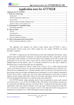
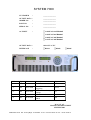
SYSTEM 7000
CUSTOMER
:
_______________
OUTPUT DATA :
_______________
ORDER NO
:
_______________
PART NO
:
_______________
SERIAL NO
:
_______________
AC INPUT
:
F 3x208VAC excl Neutral
F 3x208VAC incl Neutral
F 3x400VAC incl Neutral
F 3x415VAC incl Neutral
OUTPUT DATA :
±20A 35V or 75V
INTERFACE
FRS232
:
FRS422
REV.
By
Date
Description
Pages
1.0
DT
09.06.2004
All
1.1
DT
12.07.2004
1.2
DT
15.03.2005
1.3
JFL
22.11.2005
1.4
JFL
18.10.2006
Initial
Fast ADC and hardware
triggering
Partial reset to factory
settings
Minor corrections
Minor corrections, 415
added
FRS485
28-29
15
All
All
MANUAL
MAGNET POWER SUPPLY
SYSTEM 7000
DANFYSIK A/S ! DK - 4040 Jyllinge ! Denmark ! Tel.: +45 46 79 00 00 ! Fax.: +45 46 79 00 01
IMPORTANT!
This documentation contains information which
is the property of DANFYSIK A/S, Denmark.
It is submitted to you in confidence that it will not be
disclosed or transmitted to others without DANFYSIK=s
authorisation.
MAGNET POWER SUPPLY SYSTEM 7000
1
Table of contents
PAGE
INTRODUCTION AND SPECIFICATIONS ....................................................................................... 3
1
1.1
1.2
1.3
2
GENERAL INTRODUCTION ............................................................................................................... 3
SPECIFICATIONS .............................................................................................................................. 4
WARRANTY AND WARRANTY REPAIR ............................................................................................. 5
UNPACKING AND INSTALLATION................................................................................................. 6
2.1
2.2
2.3
2.4
2.5
2.6
2.7
3
RECEIVING THE GOODS ................................................................................................................... 6
INSTRUCTIONS FOR UNPACKING ...................................................................................................... 6
INSTALLATION REQUIREMENTS ....................................................................................................... 6
INSTALLATION ................................................................................................................................. 7
MASTER CONFIGURATION (NO PARALLEL UNITS CONNECTED) ...................................................... 7
MASTER/ SLAVE CONFIGURATION (TWO OR MORE UNIT IN PARALLEL) ......................................... 8
RS422 OR RS485 MULTIDROP CONFIGURATION ............................................................................. 9
OPERATING INSTRUCTIONS ......................................................................................................... 10
3.1
3.2
3.3
3.4
3.5
3.6
SWITCHING ON .............................................................................................................................. 10
MAIN POWER ON, OFF, STB & RESET ......................................................................................... 10
LOCAL / REMOTE CONTROL........................................................................................................... 12
CURRENT SETTING......................................................................................................................... 12
SETTING UP THE MPS.................................................................................................................... 12
DATA COMMUNICATION ................................................................................................................ 14
3.6.1
Termination using RS 422 or RS 485................................................................................... 15
3.6.2
Partial reset to factory settings.............................................................................................. 15
3.7
PROGRAMMING ............................................................................................................................. 16
3.7.1
Software Profile Programming............................................................................................. 18
3.7.2
Equal time slot ramp profile method .................................................................................... 18
3.7.3
SW limits .............................................................................................................................. 19
3.8
SW COMMANDS ............................................................................................................................ 20
4
THEORY OF OPERATIONS.............................................................................................................. 22
4.1
INTRODUCTION .............................................................................................................................. 22
4.1.1
SYSTEM 7000 Interface specification:................................................................................ 23
4.2
DISPLAY CONTROLLER MODULE. .................................................................................................. 27
4.2.1
Micro-Processor ................................................................................................................... 27
4.2.2
Display.................................................................................................................................. 27
4.2.3
DAC circuit .......................................................................................................................... 27
4.2.4
Slow ADC circuit ................................................................................................................. 28
4.2.5
Voltage reference.................................................................................................................. 28
4.2.6
Fast ADC for reading/displaying of output current .............................................................. 28
4.2.7
DC/DC Converter:................................................................................................................ 29
4.2.8
Serial Interface: .................................................................................................................... 29
4.2.9
Front Panel Interface specification: ...................................................................................... 30
4.3
POWER AMPLIFIER MODULE: ........................................................................................................ 31
4.3.1
Power Amplifier Interface specification:.............................................................................. 31
4.3.2
ON/OFF/STANDBY control................................................................................................ 33
4.3.3
Interlock and ON/OFF/STANDBY status............................................................................ 34
4.3.4
Over Current Interlock.......................................................................................................... 34
4.3.5
Out of Regulation Status ...................................................................................................... 34
4.3.6
Power Output Over Voltage Interlock.................................................................................. 34
4.3.7
Converter Over Voltage Interlock ........................................................................................ 35
DANFYSIK A/S - DK 4040 JYLLINGE - DENMARK.
MAGNET POWER SUPPLY SYSTEM 7000
2
4.3.8
Over Temperature Interlock ................................................................................................. 35
4.3.9
PS Fan Fault Interlock .......................................................................................................... 35
4.3.10 Ground Fault Interlock ......................................................................................................... 35
4.3.11 Soft start ............................................................................................................................... 36
4.3.12 Analog local/remote current set point controls..................................................................... 36
4.3.13 Slew Rate limit ..................................................................................................................... 36
4.3.14 Current limit ......................................................................................................................... 36
4.3.15 Summed Measured Current .................................................................................................. 36
4.3.16 Summed Current Error ......................................................................................................... 37
4.3.17 Analog measurements........................................................................................................... 37
4.3.18 Current Regulation ............................................................................................................... 38
4.3.19 Current Error Amplifier........................................................................................................ 39
4.3.20 Power Amplifier ................................................................................................................... 39
4.3.21 Load Dump........................................................................................................................... 40
4.3.22 Auxiliary Voltage and Ground planes .................................................................................. 40
4.3.23 Current Transducer ............................................................................................................... 40
4.4
AC/DC CONVERTER MODULE ...................................................................................................... 42
4.4.1
AC/DC Converter Interface specification ............................................................................ 43
4.4.2
Auxiliary Power.................................................................................................................... 43
4.4.3
Current mode Push-Pull regulator ........................................................................................ 44
4.4.4
Pulse Width Modulator module............................................................................................ 44
4.4.5
FET Gate driver.................................................................................................................... 45
4.4.6
Power output stage ............................................................................................................... 45
4.4.7
Power Transformer ............................................................................................................... 45
4.4.8
Output filter .......................................................................................................................... 46
5
MAINTENANCE ................................................................................................................................ 47
5.1
5.2
5.3
INTRODUCTION .............................................................................................................................. 47
PREVENTIVE MAINTENANCE ......................................................................................................... 47
ADJUSTMENT AND CALIBRATION .................................................................................................. 47
6
TROUBLE SHOOTING ...................................................................................................................... 48
7
DRAWINGS ........................................................................................................................................ 49
8
PARTS LISTS...................................................................................................................................... 49
9
PARTS LISTS STRUCTURE ............................................................................................................. 49
DANFYSIK A/S - DK 4040 JYLLINGE - DENMARK.
MAGNET POWER SUPPLY SYSTEM 7000
3
1
Introduction and specifications
1.1
General introduction
The SYSTEM 7000 is a DC constant current output Power Supplies designed for applications
requiring very high stability and low noise combined with reliability and ease of operation.
The SYSTEM 7000 is aimed at correction magnets in ion beam applications. It is the result of
an intensive development effort at Danfysik based on twenty years of experience in delivering
precision DC Power supplies to industrial and research laboratory users around the world.
Up to five SYSTEM 7000 units can be connected in a parallel Master/slave configuration. All
analogue signals are summed in the master unit. The master unit monitors and controls the
parallel connected slave units.
•
Current stability options of 100 ppm classes
•
Power outputs up to 1.5 kW per unit and 7.5kW with 5 units in parallel
•
Output current (maximum) up to 20 A Bipolar per unit and 100 A with 5 units in parallel
•
Local controlled or Remote controlled through a RS232, RS422 or RS485 serial interface
line.
DANFYSIK A/S - DK 4040 JYLLINGE - DENMARK.
MAGNET POWER SUPPLY SYSTEM 7000
4
1.2
Specifications
STABILITY CLASS . . . . . . . . . . . . . . 100 ppm
Number of output channels: . . . . . . . . . . .
DC OUTPUT RATINGS:
Output polarity: . . . . . . . . . . . . .
Power range . . . . . . . . . . . . . . . . .
Voltage . . . . . . . . . . . . . . . . . . . . .
Current range . . . . . . . . . . . . . . . .
1500W
75V
20 A
1.
BIPOLAR.
TEMPERATURE RATINGS:
OPERATING.
Ambient temperature.
Centigrade.
0 to 40
PERFORMANCE:
STORAGE temperature
-20 to 50
All drift and regulation data are given for max.
Current output.
MAIN COOLING SYSTEM.
Warm up time. (Cold start)
Warm up time. (With control power ON).
30 min
30 min
Drift:
Long term 8 hours.
100ppm
Line regulation:
+/- 10 % slow.
+/- 1 % fast.
Load regulation:
+ 10 % resistance change. T > 1 min.
Na
Na
Na
OVERALL DIMENSIONS AND WEIGHT:
MAINS CURRENT:
. . 208VAC
. . 400/415VAC
Up to 5,5 Amps pr phase
Up to 2,75 Amps pr phase
LED INDICATIONS:
MM
132.5
480.3
525
Status
Fault
Kg
25
27
ON/OFF/READY/RESET
Over-temp/Internal/AC/
Ground/External/Over
Voltage/Over Current
Remote and Local
7-segment display for indicating of:
Output Voltage
Output Current
INPUT/OUTPUT INTERFACES
COMPUTER INTERFACE:
Analogue 0±10VDC;
Set Current, Current- Current Error-Voltage-readback
RS232
RS422
RS485
Digital 5V TTL;
Control, Status, Interlock
LOAD:
Recommended below 500mH.
Loop might need adjustment to specific load.
DANFYSIK A/S - DK 4040 JYLLINGE - DENMARK.
40
MAINS VOLTAGE:
See front page
AC voltage +/- 10 %.
48 - 62 Hz.
Control mode
WEIGHT: (approx.)
Net weight . . . . . . . . . . . . . .
Shipping weight . . . . . . . . . . .
0
AC SUPPLY POWER.
T > 1 min.
T > 3 ms.
CABINET:
Height . . . . . . . . . . . . . . . . . .
Width . . . . . . . . . . . . . . . . . . .
Depth . . . . . . . . . . . . . . . . . . .
Air cooling
MAGNET POWER SUPPLY SYSTEM 7000
5
1.3
Warranty and warranty repair
DANFYSIK A/S warrants that the products manufactured by us will be free from defects in
material and workmanship that adversely would affect the normal functioning of the unit, for a
period of 18 months from the date of shipment or 12 months from the date of installation
whichever occurs first.
The exemptions to this are:
a)
Parts not manufactured by DANFYSIK A/S which are covered by the original
equipment manufacturer's warranty.
b)
Repair work, which is warranted for six (6) months from the date of shipment from
the DANFYSIK works.
DANFYSIK A/S will repair or replace either on site or at the factory, at option, any equipment
which proves to be defective within its warranty period.
In the case of warranty, DANFYSIK A/S will pay or reimburse lowest freight rate (two-way) of
any item returned to DANFYSIK or our designated agent/representative, provided that prior
written authorisation for such return has been given by DANFYSIK A/S.
This warranty shall not apply to any equipment, which has become defective or unworkable due to
mishandling, improper maintenance, incorrect use, radiation damage or any other circumstance not
generally acceptable for equipment of a similar type.
On standard products, DANFYSIK A/S reserves the right to make changes in design without
incurring any obligation to modify previously manufactured units.
The foregoing is the full extent of this warranty, and no other warranty is expressed or implied. In
no event shall Danfysik be liable for special damages arising from the delivery, late delivery or use
of the equipment.
If any fault develops, the following steps should be taken.
Notify DANFYSIK A/S, giving full details of the problems, and include Model-Type and Serial
number.
On receipt of these information, DANFYSIK A/S will give you either service information or
instructions for shipping.
All shipments of DANFYSIK equipment should be made according to our instructions and shipped
in the original or a similar container.
For smaller parts a carton will be sufficient, if the parts are wrapped in plastic or paper and
surrounded with at least 10 centimetres of shock-absorbing material.
DANFYSIK A/S - DK 4040 JYLLINGE - DENMARK.
MAGNET POWER SUPPLY SYSTEM 7000
6
2
Unpacking and installation
2.1
Receiving the goods
The Shipping container and the Power Supply should be thoroughly inspected for signs of
obvious physical damage immediately upon receipt.
All materials in the container should be checked against the enclosed packing list.
DANFYSIK A/S will not be responsible for shortages against the packing list unless notified
immediately.
2.2
Instructions for unpacking
The Power Supply is shipped in reinforced cardboard.
If the equipment is damaged in any way, a claim should be filed with the shipping agent, and a
full report of the damage should be forwarded to DANFYSIK A/S or our local agent/representative immediately.
Upon receipt of this report, you will be issued instructions for the repair, replacement or return
shipment.
Please include the Model no, Type no, Serial no, and Order no for the Power Supply on any
communication with DANFYSIK A/S or our representative.
2.3
Installation requirements
During installation of the Power Supply, local rules and regulations for electric power supplies
should be respected and the following conditions and installations should be available.
*
A normal, dust free room with humidity not above 80 % and a room temperature within 0 to
40 centigrade.
*
Three-phase Mains voltage including neutral (except 208V excl. neutral) switched and
fused.
*
Ground connection according to the local authority regulation and the requirements for the
equipment.
Please see specification sheet chapter 1.2 in this manual for actual figures for this power
supply.
DANFYSIK A/S - DK 4040 JYLLINGE - DENMARK.
MAGNET POWER SUPPLY SYSTEM 7000
7
2.4
Installation
Before and during installation of the Power Supply, the following points should be checked /
carried out.
2.5
*
Check that the main voltage and frequency matches to the specified and labelled
requirements.
*
Check that screw connections from the output terminals are tightened.
*
Check that all screws on D-sub connectors are tightened.
*
*
*
*
If the External Interlock 1 is unused, then short-circuit the terminals.
If the External Interlock 2 is unused, then short-circuit the terminals.
If the External Interlock 3 is unused, then short-circuit the terminals.
If the External Interlock 4 is unused, then short-circuit the terminals.
Master configuration (No parallel units connected)
•
The Master/ Slave slide switch, located in the back of the cabinet, must be set to Master.
•
Connect Analogue or Digital interface remote control cable if applicable.
•
Connect the termination plug in the “Parallel unit to slave” DB25 male connector located on
the back of the cabinet. (Pin 1 & 2 shorted).
DANFYSIK A/S - DK 4040 JYLLINGE - DENMARK.
MAGNET POWER SUPPLY SYSTEM 7000
8
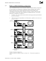
2.6
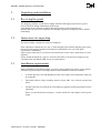
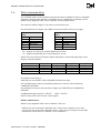
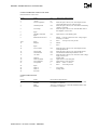
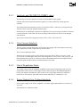
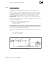
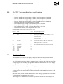
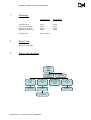
Master/ Slave configuration (two or more unit in parallel)
•
The Master / Slave slide switch located on the back of the supply must be placed in Master
position for the master unit and in slave position for all the other units. Only one SYSTEM
7000 must be configured as master.
•
Connect the “Parallel unit” interface cable between the “Parallel unit to slave” DB25 male
plug of the first unit (normal master) to the “Parallel unit to master” DB25 female plug of
the next unit and so on in a daisy chain. The first unit must have the termination plug
connected to the “Parallel unit to master” and the last unit must have the termination plug
connected to the “Parallel unit to slave”.
•
Not used external interlocks must be short-circuited.
Master
AC Main Power
Factory Program
Rack Fan
MPS status
Ac control input
External trig
Ground
fuse
Parallel units
to master
Parallel units
to slaves
External Interlocks
Slave
AC Main Power
Factory Program
Rack Fan
MPS status
Factory Program
Rack Fan
MPS status
Current
Output
Analog
Current
Output
Analog
Current
Output
Ac control input
External trig
Ground
fuse
AC Main Power
Analog
Master Slave
Parallel units
to master
Digital
Parallel units
to slaves
External Interlocks
Slave
Digital
Master Slave
Ac control input
External trig
Ground
fuse
Parallel units
to master
Digital
Parallel units
to slaves
Termination plug
External Interlocks
Master Slave
Example of a Master/Slave configuration with two slaves
DANFYSIK A/S - DK 4040 JYLLINGE - DENMARK.
MAGNET POWER SUPPLY SYSTEM 7000
9
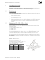
2.7
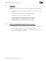
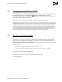
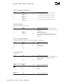
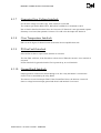
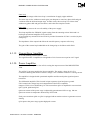
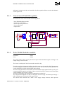
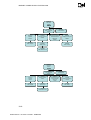
RS422 or RS485 Multidrop configuration
Up to 32 SYSTEM 7000 units can be connected in a RS422 or RS485 multidrop configuration.
It is also possible to run a Master/Slave configuration within a multidrop system. All units
must be connected in order to read the individual unit interlock status signals, but for
controlling the system only the master connection is necessary. Trying to control one of the
slaves will have no effect as the control commands are disabled on the slaves. To set up the
Master/Slave configuration, see chapter 2.6.
•
The Master / Slave slide switch located on the back of the supply must be placed in Master
position for all masters.
•
Address all units with a unique address. See SW manual doc- ApBCPsw1c.doc on how to set
up the unit address.
MPS no. Y
addresse : X+(Y-1)
AC Main Power
Factory Program
Rack Fan
MPS status
Ac control input
External trig
Ground
fuse
Parallel units
to master
Parallel units
to slaves
External Interlocks
MPS no. 3
addresse : X+2
AC Main Power
Factory Program
Rack Fan
MPS status
Factory Program
Rack Fan
MPS status
External trig
Parallel units
to master
Analog
Current
Output
Analog
Current
Output
Analog
Current
Output
Digital
Parallel units
to slaves
Master Slave
Ac control input
External trig
Ground
fuse
Parallel units
to master
Digital
Parallel units
to slaves
External Interlocks
AC Main Power
Current
Output
Ac control input
Ground
fuse
AC Main Power
Analog
Master Slave
External Interlocks
MPS no. 2
addresse : X+1
Digital
Master Slave
Ac control input
MPS no. 1
addresse : X
Factory Program
Rack Fan
MPS status
External trig
Ground
fuse
Parallel units
to master
Digital
Parallel units
to slaves
External Interlocks
Master Slave
X :Start address
Y : The last unit of MPS on the
multdrop line
Example of multidrop configuration
About the termination of RS422 or RS45, see chapter 3.6.1 “Termination using RS422 or
RS485”
DANFYSIK A/S - DK 4040 JYLLINGE - DENMARK.
MAGNET POWER SUPPLY SYSTEM 7000
10
3
Operating Instructions
This chapter describes how to operate the power supply in the local as well as in the remote
mode. It also identifies the controls and the indicators on the front panel.
3.1
Switching on
After connecting the Power Supply to the mains (line) voltage in accordance with chapter 1.2,
2.3 and 2.4, it can be switched ON.
3.2
_
Switch the main power ON
_
Set control mode to LOCAL
_
If the sum Interlock indication is set (red LED illuminates in the RESET button), press
this button to clear it. If it can’t be cleared, interlocks are present and must first be
resolved.
Main power ON, OFF, STB & Reset
The power supply can be set to three different modes for turning the power supply ON and
OFF given as below.
0) Direct ON & OFF (default mode)
1) Standby mode 1
2) Standby mode 2
The desired working mode can be selected using the ‘esc’<NFSMODE command. See the
software description for setting up the power supply and for further detail of this issue.
The working principle of the different modes is described through following state diagrams.
The circles are the state and the arrow lines are witch button, command or event that initiates
the state shift.
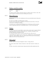
Mode 0 – Direct ON & OFF
Else
This mode is the default mode. It is
characterized by the power supply is either in the
ON or in the OFF state or if an interlock is
present in the FAULT state.
State
OFF
ON
FAULT
FAN
OFF
ON
ON
Output
Converter
Not Powered
Powered
Not Powered
DANFYSIK A/S - DK 4040 JYLLINGE - DENMARK.
ON-S
INTL
OFF
ON
RESET
OFF-S
AC Power
ON
INTL
{event}
RES
{no INTL}
OFF
{no INTL &
Off = Reset}
FAULT
Else
MAGNET POWER SUPPLY SYSTEM 7000
11
Mode 1 – ON & OFF through STANDBY
Else
In this mode the power supply must first be set into
the stand by state before entering the ON or OFF
state. An interlock puts the power supply immediately
in the FAULT state.
ON-S
OFF
INTL
{event}
RES
In the stand by mode is the output converter without
power.
State
FAN
OFF
ON
STB-1
FAULT
OFF
ON
ON
ON
ON
STB-1
Output
Converter
Not Powered
Powered
Not Powered
Not Powered
INTL
{event}
OFF
RES
{no INTL}
RES
{no INTL}
INTL
{event}
OFF-S
Else
FAULT
Else
OFF
AC Power
ON
Mode 2 – ON & OFF through STANDBY
This mode can be seen as a mixture of mode 0 and
1. Here the inserted stand by mode is actually
nearly the same as the ON state but with the output
forced to zero (compared to mode 0). An interlock
puts the power supply immediately in the FAULT
state.
Else
ON-S
INTL
{event}
ON
OFF
STB
In the stand by mode the output converter is with
power but forced to zero output.
STB-2
{Out-Dis}
OFF
State
FAN
OFF
ON
STB-2
FAULT
OFF
ON
ON
ON
Output
Converter
Not Powered
Powered
Powered
Not Powered
ON
STB
Else
INTL
{event}
Else
OFF-S
AC Power
ON
INTL
{event}
FAULT
Else
RES
{no INTL}
The STB transition is locally initiated by pressing
the reset button and thereafter at the same time the
ON button. Remotely the STB command must be
issued.
The LED inside the Reset push button indicated that the Power Supply is interlocked either due
to an internal or external fault.
DANFYSIK A/S - DK 4040 JYLLINGE - DENMARK.
MAGNET POWER SUPPLY SYSTEM 7000
12
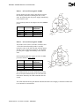
3.3
Local / Remote control
The LED “Remote” illuminates, when the Power Supply is in the REMOTE control mode and
is off in LOCAL control mode.
The control mode (LOCAL/REMOTE) is changed by pushing the "Remote" push button if the
MPS is not locked to remote line.
SYSTEM 7000 operating front panel
3.4
Current setting
In local:
The output current level can be displayed by pushing the “SET” button.
The output current display consists of six 7-segment LEDs. The left segment shows the sign. For
negative set values a minus sign will be displayed and for positive set values no sign will be
displayed. The other Segments display the set value. Each segment can be altered individually
with the up/down button. To select which segment to alter, use the forward/back button. The
chosen segment will flash.
3.5
Setting up the MPS
Two dip-switches are available for setting up of the power supply.
35V / 75V setup
The analogue ±10V output voltage read back can be scaled for either 35V or 75V
Factory settings are indicated on the back of the SYSTEM 7000 cabinet.
Output Voltage →
P803 SW1
P901 SW1
P901 SW2
35V
Closed
Closed
Closed
75V
Open
Open
Open
Bandwidth setup
For highest stability and fastest response time, the load impedance transfer function is incorporated
in the total loop gain. Therefore it is necessary to adapt the internal gain and frequency response of
the loop to match the actual connected load.
The current loop gain can be change between 1, 5 and 10 on switch P302. (1, 14 and 20dB)
The lowest loop pole can be shifted a decade upwards with switch P306.
DANFYSIK A/S - DK 4040 JYLLINGE - DENMARK.
MAGNET POWER SUPPLY SYSTEM 7000
13
Gain factor: →
P302 SW1
P302 SW2
1
Closed
Closed
Frequency Pole →
P306 SW1
Low (factory)
Closed
5
Closed
Open
10 (factory)
Open
Open
High
Open
Current / Voltage mode
This switch setting is for internal use and debugging only by authorized Danfysik service
personnel. In general it sets the unit to a voltage supply where a 20A (full scale) setting gives a
voltage output of approximately 35V.
Loop mode →
P305 SW1
P305 SW2
Current mode (factory)
Open
Closed
Voltage mode
Closed
Open
Hint:
The time constant of the magnet (transfer function of the load) can be measured, using
the SYSTEM 7000 in the voltage mode together with an attached gain/phase analyser.
Machine Protection System signal
The Machine Protection System signal (Abbreviated to “M.P.S. signal”) is available through an
Amphenol connector located on the back of the cabinet. This signal is produced by AND’ing;
the three signals; ON status, Sum Interlock and the Main contactor is on.
The M.P.S. signal is high when the SYSTEM 7000 is ON.
Sum interlock and the ON status can be excluded from the “M.P.S. signal”
Sum Interlock/ ON Status Enable / Disable
Switch ↓
Signal name ↓
P702 SW1
Sum interlock
P702 SW2
ON status
Enabled (factory)
Closed
Closed
Disabled
Open
Open
Interlock enable – disable - rerouting
Two interlocks (Ground Fault Interlock, Over Voltage) and one status signal (Out of
regulation) can be disabled if not desired.
Interlock/ Status Enable / Disable
P801 SW1
P801 SW2
P803-SW2
Interlock Ground Fault
Status Out of regulation
Interlock Over voltage
DANFYSIK A/S - DK 4040 JYLLINGE - DENMARK.
Enable
Open (factory)
Open (factory)
Open (factory)
Disable
Closed
Closed
Closed
MAGNET POWER SUPPLY SYSTEM 7000
14
3.6
Data communication
The SYSTEM 7000 uses the standard serial interface RS232 and RS422 which is compatible
with many computers and terminals. The RS422 may be configured in a multidrop system.
RS485 is only supported under certain conditions. See description below.
The connector labeled “digital” is the remote serial interface port.
Pin description for the “digital” port (DB25) located at the back of the power supply.
RS232 remote line
DB25
Pin No. Signal
2
Tx
3
Rx
25
RETURN
RS422/485 remote line
DB25
Pin No. Signal
25
RETURN
9
Tx High
10
Tx Low
11
Rx High
12
Rx Low
Rx : Signals received by the Control Module from its host.
Tx : Signals transmitted by the Control Module to its host.
NOTE! The selection between RS232, RS422 and RS485 is selected through straps on the
Display Controller Module.
Serial bus
RS232
RS422
4-Wire RS485
2-Wire RS485
Strap ST2
Open
Open
Open
Close
Strap ST3
Open
Close
Close
Open
Strap ST4
Close
Open
Open
Open
Strap ST10
Open
Open
Close
Close
The default serial setting is :
8 BIT DATA, NO PARITY AND 2 STOPBIT and baud rate 9600.
The communication is done by transmitting characters in ASCII code terminated by
CARRIAGE RETURN.
The termination characters from the Power Supply are LINE FEED and CARRIAGE
RETURN.
An ERROR message includes a "?BELL".
(Bell = ASCII 7.)
NOTE! None of the serial lines has control signals.
RS485 communication.
RS485 is only supported under certain conditions. These are:
- Disable Line turn around time: Minimum 2ms. (Time for the transmitters to tri state)
- Answer Line turn around time: Minimum 100µs t (Time after receiving the last bit of the
transmission until an answer is initiated “active transmitter”.)
DANFYSIK A/S - DK 4040 JYLLINGE - DENMARK.
MAGNET POWER SUPPLY SYSTEM 7000
15
3.6.1
Termination using RS 422 or RS 485
As standard there is no termination resistors connected inside the display controller module. An
external termination resistor of 100 Ohm must therefore be added at the end of the
communication cable or the internal 100 ohm resistor must be enabled (short-circuiting strap
ST9). The external resistor is preferable.
Hint. This resistor can be placed inside the last DB 25 plug for the remote line.
When using the RS 485 or the RS 422 line in the multi drop configuration, it is very important
during an address transfer to leave the lines at the "SPACE" state when tri stated. That is when
the line is not driven by any transmitters at all. The "SPACE" state can be utilized by adding
1K Ohm resistors to +5V (non inverting) and GND (inverting) on both the transmit and the
receive lines. The display controller module can provide this by short circuiting ST5-ST8 (use
a thin soldering iron). The 1K resistors increase the noise immunity eliminating noise to be
treated as commands thereby flawing the first character after being addressed.
3.6.2
Partial reset to factory settings
From firmware release version BCP V1.07
The partial reset to factory settings resets the baudrate and address setting to factory default.
This feature can be used when the baudrate or/and address is unknown and the operator no
longer is able to communicate with the MPS.
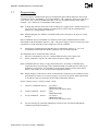
To activate the partial reset to factory settings, do following on the front panel (picture of front
panel, see page 12)
1. Hold the “▲” (up) and “▼” (down) buttons for min. 5 sec.
2. Release the buttons and the baudrate and address are reset to factory settings.
After partial reset, the setting for baudrate is:
8 BIT DATA, NO PARITY AND 2 STOPBIT and baud rate 9600
and the address is : 0
DANFYSIK A/S - DK 4040 JYLLINGE - DENMARK.
MAGNET POWER SUPPLY SYSTEM 7000
16
3.7
Programming
The power supply communication protocol is build upon plain ASCII characters where each
command or reply is delimited by a "Carriage Return" <CR> character. However a reply has a
“Line Feed” <LF> character added before the <CR> for a friendlier display when using a
terminal. <LF> characters on commands will be ignored.
Hint. Actually the protocol allows full control of the power supply from a "dumb" terminal. In
case of a service- debug- situation a terminal can be used to tap the communication
transfer by a simple parallel connection.
Hint: When debugging, the "ERRT" command enables error messages to be given as a read
able text.
More commands may be transmitted in a chain but each single command must be trailed
individually with the delimiter character <CR>. The power supply is able to execute up to 200
commands a second depending of the complexity of each command.
Ps.
Issuing short commands faster than the time to transmit the answer e.g. “S1" will
overload the internal transmit buffer regardless of the selected baud rate.
All commands can be divided into three sections.
a)
Directive commands. Eg. the "N" command that turns the power supply ON
b)
Status commands . Eg. the "S1" that returns the power supply status
Status commands delivers always a reply whereas directive- and setup- commands only
responds with an error message if the command couldn’t be understood or if the given
parameters are incorrect. It is possible to set the power supply to always generate an
answer. This feature is very useful when using RS485 protocol.
Hint. When using the "OK Answer" mode a retransmission of the last given command can be
performed if no answer or an error message is received. The System 7000 respond time
is around 5ms after receiving the last bit of the termination character.
Answer scheme if set to “Always Answer” mode.
c)
d)
e)
Ps.
Directive commands.Answer: - No answer
- ERROR message
- OK if set to OK answer mode
Status commands . Answer: - Data
- ERROR message
Set up commands. Answer: - No answer
- ERROR message
- OK if set to OK answer mode
An error message is generated immediately when an error is detected although the
command isn’t fully transmitted.
DANFYSIK A/S - DK 4040 JYLLINGE - DENMARK.
MAGNET POWER SUPPLY SYSTEM 7000
17
Below is an example written in BASIC on how to turn ON the power supply and read the status
without and with acceptance answer:
Turning the power supply ON and reading/evaluating the status with always answer disabled.
LPRINT "N"+CHR$(13)
LPRINT "S1"
LINPUT S1$
IF LEFT$(S1$,1) = CHR$(?)
GOTO ERROR_HANDLING
ENDIF
J=1
DO
IF MID$(S1$,J,1)="!"
GOSUB STATUS(J)_ACTIVE
ELSE
GOSUB STATUS(J)_ACTIVE
ENDIF
J=J+1
UNTIL J=24
:REM Turns the power supply on
:REM Issues the status command
:REM Read the MPS reply
:REM Is it an error message reply?
:REM Yes then go to error module
:REM evaluate status reply
:REM set this status bit active
:REM set this status bit inactive
Turning the power supply ON with always answer enabled
J=0 :ERROR$=”“
DO
J=J+1
:REM Counter for maximum attempts
LPRINT "N"+CHR$(13)
:REM Turns the power supply on
LINPUT RE$
:REM Read the MPS reply with 0.1 Sec. time out
IF LEFT$(RE$,1) = CHR$(?)
:REM Is it an error reply?
ERROR$=RE$
:REM Mark the error code
ELSEIF RE$=”OK”
:REM Is it a good reply
BRAKE
:REM then exit DO loop
ELSEIF J=6
:REM Try only six times
IF LEFT$(ERROR$,1) = CHR$(?) :REM Was it error reply?
GOTO ERROR_HANDLING:REM Yes then go to error module
ELSEIF
GOTO NO_COMMUNICATION :REM Yes then go to “No answer” error module
ENDIF
ENDIF
UNTIL -1
:REM loop endless
Ps.
An ERROR message includes a "?BELL".
DANFYSIK A/S - DK 4040 JYLLINGE - DENMARK.
(Bell = ASCII 7.)
MAGNET POWER SUPPLY SYSTEM 7000
18
3.7.1
Software Profile Programming
SYSTEM 7000 is delivered with the software profile option.
With the ramp profile SW it is possible to down load and run a predefined ramp sequence that
the output current must follow. The SYSTEM 7000 supports Equal timeslot method.
The examples below are shown for a uni-polar profile. For bipolar profiles, the output current
may also be set as negative.
3.7.2
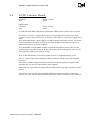
Equal time slot ramp profile method
With the ”Equal time slot method” it is possible to download up to 512 current set values and a
single time slot value, that will be used for all set values. Only one stack is available.
This profile method is especially useable for faster and more accurate curves fitting profiles
e.g. as a function generator.
To use the Equal time slot method at least the following steps must be preformed:
- Clear and set the stack “RAMPSET [parameter]”,- Program the stack “R [parameter]”, -Start
the stack “RAMP [parameter]”, -Read the status of the running stack “RAMP".
PS.
All values must be given as a floating point number scaled to “1.00000". That is; 2.5ms
must be entered as 0.00250 and 19.54% output current as 0.1954.
Please refer to ApBCPsw1a.doc Software commands for full instructions.
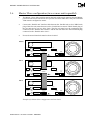
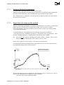
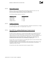
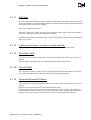
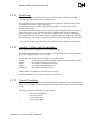
The figure below shows an example of one ramp profile stack. (Ps. not all 512 points need to
be programmed, empty entries will be ignored.)
Software Ramp Profile
Equal Time Slot Method
Output
Current
15
20
10
Incremental
2
5
3 4
1
25
26 27
Time
From
TRIG
Time Slots
The time slot must be given as a multiple of 2.5ms. Between 2.5ms to 1 second. Any value inbetween will automatically be rounded according to formulae:
{time slot}=frac({time}/0.00250)*0.00250
DANFYSIK A/S - DK 4040 JYLLINGE - DENMARK.
MAGNET POWER SUPPLY SYSTEM 7000
19
The SW will after the start command update the output current every 2.5ms. By means of
interpolation regardless of the programmed time slot value:
The ramp can be initiated to run as a single shot “RAMP R”, auto iteratively (auto loop) by
software command “RAMP R,L” or HW triggered auto armed “RAMP T,W”. For a full
documentation on controlling the “Equal time slot method” please refers to ApBCPsw1a.doc
Software commands.
If synchronization to an eternal event is required, it is possible to arm the ramp sequence first
with the synchronization command “RAMP T”. A hardware signal on the trigger input X7 pin
1&2 (10 to 24V) or a “RAMP R” command will start the sequence.
If more power supplies have to be synchronized, one of the supplies has to be appointed as
master. Connecting the master trig output X7 pin 3&4 to the other supplies trig input will start
the other supplies when the master is triggered. A maximum skew of 2.5ms between the
supplies may be expected. (an external 15V auxiliary supply is needed, as the trig output is an
open collector and the trig input is an opto coupler input.)
External input and output triggers are located on the back of the SYSTEM 7000, see overview
of the back of SYSTEM 7000 in chapter 4.1.1
Hint: When adding values to the ramp profile, the enter point (start) and exit point (stop) shall
be the same in order for running the ramp sequence in loop. Otherwise there will be an
unwanted level between the exit point for the first ramp and the enter point for the next
ramp as the ramp is miscalculated. Besides, the output current should set to zero before
start running the ramp.
In order to run ramp profile correctly, following steps must be performed
• Clear the stack by typing RAMPSET C
• Enter the data points, type R 0.xxxxx and press enter. Repeat this until the last data
point has been entered.
• Save the data points by typing R S
• Set the output current to zero by typing WA 0 or DA 0,0
• Turn on the MPS by typing N
• Run the ramp in loop by typing RAMP R,L
x is a number from 0 to 9
Description of how to set up and run the ramp profile, refer to the ApBCPsw1a.doc Software
command
3.7.3
SW limits
The limits of the “Equal time slot method” ramp profile SW are:
-
The set value must be given in a floating point representation normalized to
1.00000.
The time slot may be between 0.0250 to 1 second given in a floating point
representation normalized to 1.0000.
Maximum numbers of stacks = 1
Maximum number of time slots in a stack = 512
DANFYSIK A/S - DK 4040 JYLLINGE - DENMARK.
MAGNET POWER SUPPLY SYSTEM 7000
20
3.8
SW Commands
Following are the commands for the standard software listed in alphabetic order.
Please see the ApBCPsw1a.doc Software command for detail explanation on every command.
This issue is valid for software version BCP100
STANDARD COMMANDS. summary
AD X
ADR
ADR XXX
Read value from an ADC
channel.
Read the address of the MPS.
Write an address to a MPS.
ADCTRIG
Read the AD channel trig setup
CMD
CMDSTATE
Read current control mode.
Read current control state.
DA 0,XXXXXX Writes a value to an Digital to
Analog converter for setting the
output current. (Alternative to
the WA command.)
S1
S1H
Read the internal status.
Read internal status in HEX
format
STB
Standby (Main Power ON
with clamped output in
ON/OFF/STB mode 2)
TD
Test DAC
TYPE
AD type in use
UNLOCK
Unlock the MPS
Reads the software version
ERRC
ERRT
Coded error message.
Text string error message.
VER
F
Main Power OFF
LALL
LOC
LOCK
Listen ALL.
Change to Local Control
Lock the MPS in Local Control.
WA XXXXXX Writes a value to an Digital to
Analog converter for setting the
output current. (preferred
command DA 0,XXXXXX.)
N
NERR
Main Power ON
No error message
PO
PO +/-
Polarity status
Change to Normal polarity
PRINT
Reads internal user information
about the MPS.
RA
REM
RLOCK
RS
Read the set value.
Change to remote control.
Remote line only
Reset interlocks.
X is a number from 0 to 9 and Commands in quotation marks are optional
DANFYSIK A/S - DK 4040 JYLLINGE - DENMARK.
MAGNET POWER SUPPLY SYSTEM 7000
21
Following are the commands for the standard software listed in alphabetic order.
Please see the ApBCPsw1a.doc Software command for detail explanation of every command
This issue is valid for software version BCP100
STANDARD COMMANDS. summary
ESC<ADR
Configures the communication
address setting (in RS422
mode).
ESC<DASET
Auto Configures the scaling
(gain) and Offset for a DA
converter channel.
ESC<ADSET
Auto Configures the scaling
“gain” and Offset for an AD
converter channel.
ESC<LINE
Configures the protocol for the
serial lines.
ESC<BAUD
Configures the Baud rate for the
serial lines.
ESC<NFSMODE
Configures the ON/OFF/STB
mode operation
ESC<COLDBOOT
Configures the power up state
(Wake up position)
ESC<CPURESET
Hardware reset / CPU reset
Following are the commands for the software driven “RAMP PROFILE” listed in alphabetic
order.
Please see the SW appendix for parameter format and further detail description.
These commands are optionally available.
SW RAMP PROFILE COMMANDS “Equal Time slot method”. Summary
R
Write data to the stack.
RAMP
Control the stack operation
RAMPSET
See ApBCPsw1c.doc for detail Software commands
DANFYSIK A/S - DK 4040 JYLLINGE - DENMARK.
Configure the ramp operation
MAGNET POWER SUPPLY SYSTEM 7000
22
4
Theory of operations
4.1
Introduction
The power supply is designed to supply a magnet with direct current stabilised to 100 ppm of
maximum output current.
The main AC input supply is connected through a contactor, which turns on the power in two
steps to minimise the inrush current. Step one with R201 to R204 connected in parallel with the
mains for a certain time. In the second step the resistors will be short circuit. The voltage is
rectified in a 6-pulse rectifier and filtered with a L_C low pass filter.
The output current is controlled by means of a linear Vce controlled four-quadrant power
amplifier.
One power supply is capable of transforming up to 1,5KW of power at a maximum of 20A and
75V. If more current is required up to five power supplies may be arranged in parallel.
A 70 kHz Push-Pull converter supplies the Power Amplifier. The Vce voltage of the Power
Amplifier controls this converter.
Stabilisation is achieved by comparing the voltage across the burden resistor, connected to an
ultra high precision D.C. current transformer (DCCT), with the ±10V set signal either supplied
from the Analogue interface or the built in precision DAC.
The resultant error signal is feed into a high gain amplifier system. The output from this
amplifier controls the output power amplifier, so that the output current is maintained within
the specified accuracy.
Due to safety reasons it is possible to stop (interlock) the power supply. These interlocks can
either be generated internally (phase_, temperature_, over voltage_, over current_ failures and
others) or externally (two spare_, Magnet over temperature_ or rack fan_failure). These
interlocks are latched on the power amplifier module.
It is possible to control the power supply either from the local control panel located on the front
of the supply, through the remote serial line or through the “PARALLEL UNITS TO
MASTER” and “PARALLEL UNITS TO SLAVE” interface plugs, allowing a parallel control
and analogue current settings. In all modes it is possible to switch the supply ON/OFF, reset
interlocks, read status information as interlocks, internal voltages and output current/voltage.
The slaves must also be connected to the serial line in order to read these individual interlocks.
Efforts have been taken to design the power supply to be fully protected if an error occurs.
However if magnets above 500mH is connected, fast ramping beyond regulation e.g. polarity
change from full positive to full negative set current, might bring the output transistors beyond
SOA. The ensure best protection, it is recommended to adjust the slew rate circuit to the
maximum needed ramp speed and not ramp faster than the loop can regulate.
DANFYSIK A/S - DK 4040 JYLLINGE - DENMARK.
MAGNET POWER SUPPLY SYSTEM 7000
23
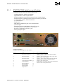
4.1.1
SYSTEM 7000 Interface specification:
SYSTEM 7000 has following external connections:
-
Analogue Interface, D-sub 9 pole female
Digital Interface, D-sub 25 pole female
Parallel unit Master, top position connector D-sub 25 pole female
Parallel unit Slave, bottom position connector D-sub 25 pole female
AC main input, 3 phase, Neutral and Earth
AC Control input
Earth Screw
MPS Status, Amphenol 4 pole series C091B female
Current output
External trig (for use with Ramp or fast ADC) 4 pole
External interlocks, Weidmuller 151-096, 8 pole
Rack Fan, Weidmuller 151-096, 2 pole
Factory program 6 pole
Connector ANALOG:
Analogue status and analogue set value interface.
Pin no:
Name
I/O
Description & Specification
1
Measured Current Error
O
2
Measured Voltage
O
3
Measured Current
O
4
5
Current Setpoint readback O
Current Setpoint
I
Output is 5V per 1% in difference between output
current and SET current.
Output is 10V if output voltage is 35V or 75V. This
depends on dip switch setting.
Output is 10V for 100% output current 20A one unit
and 40A when two units are in parallel and etc.
Output is equal to SET value.
Input setponit, 10V equal to 20A for one unit and 40A
when two units are in parallel and etc.
6
7
8
9
Measured Shield
Measured RTN
Setpoint Shield
Setpoint RTN
DANFYSIK A/S - DK 4040 JYLLINGE - DENMARK.
O
O
I
I
MAGNET POWER SUPPLY SYSTEM 7000
24
Connector DIGITAL:
Remote, RS232, RS422, RS485 DB25 serial line Interface
Pin no:
2
3
7
9
10
11
12
Name
Tx
Rx
RETURN
Tx High
Tx Low
Rx High
Rx.Low
I/O
O
I
I/O
O
O
I
I
Description & Specification
RS232 Transmitter line
RS232 Receiver line
Return line for RS232
RS422/485 Transmitter positive line
RS422/485 Transmitter negative line
RS422/485 Receiver positive line
RS422/485 Receiver negative line
Connector PARALLEL UNITS TO MASTER:
Parallel hardware control P112
Pin no:
1
Name
+Power is ON
I/O
O
Description & Specification
Power ON chain. All parallel units will go OFF if one
unit drops out.
2
3
Spare
/Out of regulation
I/O
4
/Summary fault
I/O
5
/Over temp
I/O
Interlock Open collector, low when output current
exceeds the limit of 2,5% of the set value
Interlock Open collector, low when SCR in Start/Stop
control is activated.
Interlock Open collector, low when the heat-sink of
the amplifier is above 80°C
6
7
8
9
Spare
/Standby command
Spare
Summed current error
10-11
12
Spare
Setpoint
13
14
I/O
Open collector, low Standby pulse.
I
O
Master : Converts current into error voltage signal
scaled by no of units.
Slave : 1 mA per 2% error per unit
O
I
Master
Slave
Spare
/Over current
I/O
15
16
17
/PS fan fault
/Ground fault
/AC fault
I/O
I/O
I/O
18
19
20
21
GND D
/OFF command
/ON command
Unit parallel
Interlock Open collector, low when output current
reach adjusted level
Interlock Open collector, low when inside fan fail.
Ground fault automatically disabled in slaves
Interlock Open collector, low when one of the voltage
supply lines are low.
Digital GND
Open collector, low OFF pulse
Open collector, low ON pulse
Master : X mA = X slaves.
Slave : 1 mA sink per unit
22
23
24
25
Spare
GND A
GND A
Not used
DANFYSIK A/S - DK 4040 JYLLINGE - DENMARK.
I/O
I/O
I
O
I
Loop GND
Analog GND
MAGNET POWER SUPPLY SYSTEM 7000
25
Connector PARALLEL UNITS TO SLAVES:
Parallel hardware control P111
Pin no:
1
2
3
Name
-Power is ON
-15VD
/Out of regulation
I/O
I
O
I/O
4
/Summary fault
I/O
5
/Over temp
I/O
6
7
8
9
Spare
/Standby command
Spare
Summed current error
10-11
12
Spare
Setpoint
13
14
Description & Specification
Interlock Open collector, low when output current
exceeds the limit of 2,5% of the set value
Interlock Open collector, low when SCR in Start/Stop
control is activated.
Interlock Open collector, low when the heat-sink of
the amplifier is above 80°C
I/O
Open collector, low Standby pulse.
I
O
Master : Converts current into error voltage signal
scaled by no of units.
Slave : 1 mA per 2% error per unit
O
I
Master
Slave
Spare
/Over current
I/O
15
16
17
/PS fan fault
/Ground fault
/AC fault
I/O
I/O
I/O
18
19
20
21
GND D
/OFF command
/ON command
Unit parallel
Interlock Open collector, low when output current
reach adjusted level
Interlock Open collector, low when inside fan fail.
Ground fault automatically disabled in slaves
Interlock Open collector, low when one of the voltage
supply lines are low.
Digital GND
Open collector, low OFF pulse
Open collector, low ON pulse
Master : X mA = X slaves.
Slave : 1 mA sink per unit
22
23
24
25
Spare
GND A
GND A
Not used
I/O
I/O
I
O
I
Loop GND
Analog GND
Connector MPS STATUS:
P103
Pin no:
1
2
3
4
Name
MPS
PIN2&4
MPS
PIN2&4
DANFYSIK A/S - DK 4040 JYLLINGE - DENMARK.
Description & Specification
This pin is conncted to pin 3 when the SYSTEM 7000 is ON.
Pin 2 and 4 is connected
This pin is conncted to pin 1 when the SYSTEM 7000 is ON.
Pin 2 and 4 is connected
MAGNET POWER SUPPLY SYSTEM 7000
26
Connector EXTERNAL INTERLOCKS:
Pin no:
1
2
3
4
5
6
7
8
Name
EXT 1
RTN GND
EXT 2
RTN GND
EXT 3
RTN GND
EXT 4
RTN GND
I/O
I
Description & Specification
+15V connected to RTN GND if no interlock.
I
+15V connected to RTN GND if no interlock.
I
+15V connected to RTN GND if no interlock.
I
+15V connected to RTN GND if no interlock.
Description & Specification
Applying a 15 to 25 V signal between pin 1 and 2
will start the SW ramp profile if armed or trig signal
for ADC 0
Return wire for pin 1
Return line for SYNC +O
Open collector output up to 24V/100mA. Active in
minimum 2.5ms when a ramp profile has been
triggered.
Connector EXT TRIG:
Ramp profile synchronization / ADC trig
Pin no:
1
Name
SYNC+I
I/O
I
2
3
4
SYNC-I
SYNC-O
SYNC+O
I
O
O
Connector FACTORY PROGRAM :
Software upgrade plug X2. Only to use by authorized Danfysik service personnel.
Pin no:
1
2
3
4
5
6
Name
ISOGND
RESET
Rx
Tx
I/O
I
I
O
ISO5V
Description & Specification
Ground
Reset
Receiver line
Transmitting line
5V
Connector RACK FAN:
Auxiliary fan
Pin no:
1
Name
Fan 1
I/O
O
2
Fan 2
O
Description & Specification
NO contact for auxiliary fan close in standby and on
mode. Contact may be loaded with maximum
220VAC/0.5A
See above
I/O
Description & Specification
Connector AC MAIN INPUT:
Pin no::
Name
1
2
3
Earth
L1
L2
L3
I
I
I
I
Green/Yellow
Line 1
Line 2
Line 3
Earth screw
Pin no:
1
Name
6mm
I/O
Description & Specification
Safety Ground
DANFYSIK A/S - DK 4040 JYLLINGE - DENMARK.
MAGNET POWER SUPPLY SYSTEM 7000
27
4.2
Display controller module.
Schematic:
Assy.:
85089-1 & 2
85088
The display controller module contains the display, local buttons, DAC for the set value, ADC
for the read back, serial interface and the controlling micro-processor.
4.2.1
Micro-Processor
The micro-processor circuit is the intelligent part of the system and build around a Zilog microprocessor U8,
The CPU runs at 20MHz, controlled from the crystal Y1.
The micro-processor has built-in "Watchdog" circuit and will reset the CPU, if it for some
reason stops to refreshing the watchdog.
As memory it uses its internal FLASH EEPROM for the PGM storage and U20 as the data
storage “FRAM type FM25CL64-S with 64Kbit capacity” as well as its internal RAM.
4.2.2
Display
The display consists of 12 single LEDs for status and 2x6 common anode 7-segments LEDs for
displaying set/output currents and voltage respectively. The display refreshment is done
through multiplexing controlled by the CPU.
For driving the segments, buffer U9 and U18 with transistor Q1 and Q2 are used.
Connecting the power supply as slave in a master slave configuration (in parallel with another
supply) the 7 segment display of the slaves will be turned off. The master will automatically
display the total current of all paralleled units.
4.2.3
DAC circuit
The DAC circuit converts the serial digital set value to a voltage reference.
The circuit is built around U1 for the I-reference set value and U10 for the V-reference set
value.
The DAC circuit delivers a bipolar output voltage proportional with the digital input value.
DANFYSIK A/S - DK 4040 JYLLINGE - DENMARK.
MAGNET POWER SUPPLY SYSTEM 7000
28
4.2.4
Slow ADC circuit
Different voltages are monitored by means of the Analog to Digital converter U19. The
measured values and their resolution are shown in the table below.
The 2.5V reference voltage for the ADC converter comes from U25.
The following analogue signals are monitored:
VALUE
Output current
Current Limit
Output Voltage
Voltage Limit
Voltage reference
4.2.5
BIT RESOLUTION
17 + sign
17 + sign
17 + sign
17 + sign
17 + sign
Voltage reference
The voltage reference circuit is constructed around U25 “MAX6350” which delivers a 5V high
precision voltage to the ADC “U19” and the DAC “U1 & U10”.
4.2.6
Fast ADC for reading/displaying of output current
From PCB revision B
The ADC U19 has a sample rate of 1 second. If a faster sample rate is required, the fast ADC
circuit can be selected by inserting strap ST11. The fast ADC is capable of converting the
output current up to 30 times a second with a resolution of 12 bit + sign. The sampling may be
synchronized from an external trig signals SYNC+I and SYNC-I on connector X6. For
enabling the external ADC trig, pin 16 on connector X7 need to be set low (high-to-low
transition) otherwise the fast ADC will run continuously at highest speed.
The fast ADC circuit is built around A4A and A4B together with two of the CPU internal ADC
channels in an average over sampling technique.
The sampling frequency of these two channels is 10 kHz each, but due to the running average
calculation, to achieve the 12 bit accuracy from the 10 bit internal ADC, is the practice
sampling rate reduced to 30Hz.
The sign for the fast ADC reading is built around a comparator LM311.
DANFYSIK A/S - DK 4040 JYLLINGE - DENMARK.
MAGNET POWER SUPPLY SYSTEM 7000
29
For enabling fast ADC mode, strap ST11 must be short-circuited (close) otherwise it is normal
mode.
Mode
Fast ADC
Normal
Strap ST11
Close
Open (default)
The maximum frequency for the ADC external trigger pulse is 30 Hz.
Trig mode
ADC External trig
Running
Pin16 (connector X7)
Low 1)
High2) (default)
1) Short-circuit pin 8 and pin 16 at the connector X7
2) Pin 16 is high at default
Ps. The fast ADC external trig input and the external trig for the ramp profile share the same
physical port line. Due to this, the external trig for ramp profile option will automatically
be disabled if the fast ADC external trig is enabled.
4.2.7
DC/DC Converter:
A small 100 kHz 5W galvanic isolated push pull converter is provided. It supplies circuits with
two isolated +5V suppliers. Galvanic isolation is used to avoid ground loops.
A voltage mode pulse width modulator, U30 is controlling the push pull converter.
±5V for the ADC is generated from two linear regulators, U23 and U24
+3.3V for the :-processor is generated from Low-Noise Ultra Low-Dropout Regulator U26.
4.2.8
Serial Interface:
The SYSTEM 7000 supports serial communication RS232, RS422 and RS485. The default
setting is RS422.
The serial communication circuit consists of U39, U35, U36, U37A, ISO5, ISO6 and ISO9 and
the serial link is optically isolated.
The connector “REMOTE CONTROL” is the serial interface port. For information about pin
description for this connector at the back of the power supply, please refer to chapter 3.6.
The selection between the RS232, RS422 and RS485 mode is done through straps located on
the Display Controller Module. Please refer to chapter 3.6 about strap settings.
DANFYSIK A/S - DK 4040 JYLLINGE - DENMARK.
MAGNET POWER SUPPLY SYSTEM 7000
30
4.2.9
Front Panel Interface specification:
The Front Panel has following connection:
Connector X1: (Analog signals To/From the Front Panel)
Pin no:
Name
I/O
Description & Specification
1
2
3
4
5
6
7-10
11-12
13-14
15-16
Local Reference
Current Limit
Voltage Measured
Current Measured
Current Setpoint
Number of units in parallel
Spare
+15V
-15V
GNDA
O
O
I
I
I
I
0 - ±10VDC from DAC circuit in Front Panel
0 - +10VDC from current limit potentiometer.
0 - ±10VDC to BNC connector in Front Panel
0 - ±10VDC to BNC connector in Front Panel
0 - ±10VDC to BNC connector in Front Panel
1-7VDC to ADC in Front Panel
I
I
Connector X4: (Digital signals To/From the Front Panel)
Pin no:
Name
I/O
Description & Specification
1
2
3
4
5
6
7
8
9
10
11
12
13
14
15
16
17
18
19
20
21
22
Local, /Remote
/OFF Local
OFF status
/Standby,/Reset
Standby status
/ON Local
ON status
Over Current Interlock
Over Voltage Interlock
Over Temperature Interlock
PS Fan Fault Interlock
Out of Regulation Interlock
Ground Fault Interlock
AC Fault Interlock
Summary Interlock
Magnet Over Temperature Interlock
Rack Airflow Interlock
Spare 1
Spare 2
In Current Limit
Converter Over Voltage Interlock
Master, /Slave
O
O
I
O
I
O
I
I
I
I
I
I
I
I
I
I
I
I
I
I
I
I
23
75V, /35V
I
24
25
26
27-28
29-30
31-34
35-40
Unit0
Unit1
Unit2
B+5V
GNDD
+15VUREG
GNDUREG
O
O
O
I
Signal from :-Processor 0V=Remote, 5V=Local
Active low signal from push button in Front Panel
5V to OFF status LED
Active low signal from push button in Front Panel
5V to Standby status LED
Active low signal from push button in Front Panel
5V to ON status LED
5V to Over Current Interlock LED
5V to Over Voltage Interlock LED
5V toOver Temperature Interlock LED
5V to PS Fan Fault Interlock LED
5V to Out of Regulation Interlock LED
5V to Ground Fault Interlock LED
5V to AC Fault Interlock LED
5V to Summary Interlock LED
5V to External Magnet Over Temperature Interlock LED
5V to External Rack Airflow Interlock LED
5V to External Spare 1 Interlock LED
5V to External Spare 2 Interlock LED
5V to In Current Limit LED
5V to Converter Over Voltage Interlock LED
Display in Front panel is off in Slave mode. 5V=Master,
0V=Slave
:-Processor is scaling Voltage Display to 35V or 75V.
5V=75V, 0V=35V
Unit 0-2 is 3 bit showing no of units in parallel.
The 3 bit scales the summed regulation error to 2%=10V.
The 3 bit scales the measured current to 100%=10V.
DANFYSIK A/S - DK 4040 JYLLINGE - DENMARK.
I
I
Supply For DC/DC Converter
MAGNET POWER SUPPLY SYSTEM 7000
31
4.3
Power Amplifier module:
Schematic:
Assy.:
84571 (9 sheets)
84570
The Power Amplifier module has the following functions on board;
Power amplifier interface specification.
ON/OFF/STANDBY control.
Protection circuits and Interlock.
Analog Local/ Remote current SET point controls.
Analog measurements.
Current regulation
Power Amplifier.
Load dump circuit.
DC Current Transducer.
Interface to Display & AC/DC Converter.
+5V linear regulator.
Two modules are connected to the Power Amplifier module;
1) The Power Converter module. See description in Converter section
2) The Display panel. See description in Display section.
4.3.1
Power Amplifier Interface specification:
The Regulation module has following connection:
-
P108: Analog signals to Front Panel, Header 16 pole for ribbon cable
P110: Digital signals to Front Panel, Header 40 pole for ribbon cable
P115: Internal Fan 24VDC, Molex serie 231, 2 pole
P116: Amplifier supply voltage +V, Faston Receptacles 6,3x0,8mm
P117: Amplifier supply voltage GND, Faston Receptacles 6,3x0,8mm
P118: Amplifier supply voltage –V, Faston Receptacles 6,3x0,8mm
P119: Converter control, Header 26 pole for ribbon cable
Connector P108: (Analog signals To/From the Front Panel)
DANFYSIK A/S - DK 4040 JYLLINGE - DENMARK.
MAGNET POWER SUPPLY SYSTEM 7000
32
Pin no:
Name
I/O
Description & Specification
1
2
3
4
5
6
7-10
11-12
13-14
15-16
Local Reference
Current Limit
Voltage Measured
Current Measured
Current Setpoint
Number of units in parallel
Spare
+15V
-15V
GNDA
I
I
O
O
O
O
0 - ±10VDC from DAC circuit in Front Panel
0 - +10VDC from current limit potentiometer.
0 - ±10VDC to BNC connector in Front Panel
0 - ±10VDC to BNC connector in Front Panel
0 - ±10VDC to BNC connector in Front Panel
1-7VDC to ADC in Front Panel
O
O
Connector P110: (Digital signals To/From the Front Panel)
Pin no:
Name
I/O
Description & Specification
1
Local, /Remote
I
2
3
4
5
6
7
8
9
10
11
12
13
14
15
16
17
18
19
20
21
22
/OFF Local
OFF status
/Standby,/Reset
Standby status
/ON Local
ON status
Over Current Interlock
Over Voltage Interlock
Over Temperature Interlock
PS Fan Fault Interlock
Out of Regulation Interlock
Ground Fault Interlock
AC Fault Interlock
Summary Interlock
Magnet Over Temperature Interlock
Rack Airflow Interlock
Spare 1
Spare 2
In Current Limit
Converter Over Voltage Interlock
Master, /Slave
I
O
I
O
I
O
O
O
O
O
O
O
O
O
O
O
O
O
O
O
O
23
75V, /35V
O
24
Unit0
I
25
26
27-28
29-30
31-34
35-40
Unit1
Unit2
B+5V
GNDD
+15VUREG
GNDUREG
I
I
O
Signal to analog switch controlling local and remote SET
value.
Active low signal to Start/Stop control circuit
5V from buffer
Active low signal to Start/Stop control circuit
5V from buffer
Active low signal to Start/Stop control circuit
5V from buffer
5V from buffer
5V from buffer
5V from buffer
5V from buffer
5V from buffer
5V from buffer
5V from buffer
5V from buffer
5V from buffer
5V from buffer
5V from buffer
5V from buffer
5V from buffer
5V from buffer
Signal from Master/Slave switch placed in back of SYSTEM
7000. 5V=Master, 0V=Slave
Signal from dip-switch setting 35V or 75V. 5V=75V,
0V=35V
Unit 0-2 is a 3 bit signal to analog switches. The switches are
controlling the voltage scaling.
The 3 bit scales the summed regulation error to 2%=10V.
The 3 bit scales the measured current to 100%=10V.
Connector P115: (To/From the Fan)
DANFYSIK A/S - DK 4040 JYLLINGE - DENMARK.
O
O
Unregulated auxiliary supply voltage from AC/DC Converter
MAGNET POWER SUPPLY SYSTEM 7000
33
Pin no:
Name
I/O
Description & Specification
1-2
Fan contactor
O
ON/ OFF contactor for the internal FAN
I/O
Description & Specification
Connector P119: (To/From the Converter)
4.3.2
Pin no:
Name
1
Output Voltage of Power Amplifier O
2
3
ON
PWR ON+
O
I
4
5
6
7
8
9-14
15-16
17-18
19-20
21-22
23-26
PWR ONAC Fault
PWR Contact
ON Relay
Inrush Relay
Spare
+15VUREG
GNDUREG
B+5V
+15V
GNDS
I
I
I
O
O
SYSTEM 7000 output voltage feedback to AC/DC Converter
for Vce regulation.
Converter pulse width modulator ON/OFF. 5V=ON.
Cathode of opto coupler. Opto coupler keeps SYSTEM 7000
ON
ON chain signal to parallel cable.
Input of AC Fault camparator. OK=15V.
Part of Machine Protection System signal. ON=0V.
Open collector. Main contactor ON/OFF. 0V=ON,
Open collector. Inruch relay. 0V=End of inruch time.
I
I
I
ON/OFF/STANDBY control
SYSTEM 7000 has three ON/OFF/STANDBY modes. See chapter 3.2 for more information
about these modes.
Remote ON, Standby and OFF pulse is pulse shaped by U201.
A delay-line ensures that sum interlock signal (named SET on sheet 2) is only accepted, if it
stays high for a longer time than app. 50 mSec.The delay circuit consists of R251, C207, R252
and C208. The purpose is to eliminate false noise generated interlocks. The output of the delayline will trigger Q209, Q212 that acts like a thyristor and thereby turning the transistor Q210
and Q214 off that controls the main contactor. The sum interlock signal is also connected to
Q212 for a latched interlock indication.
Turning the power supply ON is initiated by turning Q211 on with a pulse. /ON_PULSE will if
allowable (no interlock) conduct thereby turning the main contactor on. This will in turn
activate the PWR_ON line that will direct Q210 on, and thereby permit the power supply to
stay on. If though for some reason the main contactor doesn’t goes on within the ON pulse time
of Q211 will the ON sequence be terminated.
Turning the power supply OFF (as a response to a command from the local control panel or the
remote line) will activate Q207 that forces Q210 and Q211 OFF.
For safety reasons the main interlock chain is hard wired.
DANFYSIK A/S - DK 4040 JYLLINGE - DENMARK.
MAGNET POWER SUPPLY SYSTEM 7000
34
4.3.3
Interlock and ON/OFF/STANDBY status
This block processes the interlock and ON/OFF/STANDBY status signals.
Internal and external interlock and status signals are connected directly without galvanic
isolation.
The latched interlock information can be seen from the LED’s, on the local control panel and
from the remote serial line (Digital interface plug).
Each interlock is individually connected to a SR latch. Every time an edge transition is detected
it will be latched in a SR latch. The first one though will be latched on arrival of the delayed
sum interlock.
This circuit consists of the integrated circuits U701, U705, U707 and U712.
4.3.4
Over Current Interlock
The task of the overload protection is to turn the power supply OFF if the output current rises
above adjusted level that is adjustable by means of P807.
This circuit is build upon U807.
When the power supply delivers 100% output current, the DCCT delivers exact 0,1A. This
0,1A current is fed through a 10S resistor in the Regulation Circuit, sheet 2, and giving 1V and
then amplified by 10 gives10V. If this rises above adjusted threshold at the comparator U807,
transistor Q804 will open and an overload interlock is activated.
4.3.5
Out of Regulation Status
The output voltage from the "ERROR" amplifier located in the compensation loop circuit is
proportional to the accuracy of the output current. Since the gain in the ERROR amplifier is
known, the window discriminator U802 is able to test, if the output current lies within the
desired level. The window span (R807, R814, R822 and R824) is calculated to 2.5%.
4.3.6
Power Output Over Voltage Interlock
If the output voltage of the Power Amplifier exceeds the adjusted threshold level, interlock is
activated.
Threshold level is adjusted at P802.
DANFYSIK A/S - DK 4040 JYLLINGE - DENMARK.
MAGNET POWER SUPPLY SYSTEM 7000
35
4.3.7
Converter Over Voltage Interlock
If Converter voltage rises above app. 100V, interlock is activated.
The window span (R828, R829, R833, R834, R837 and R839) is calculated to 100V.
Due to limit in Interface Interlock lines, the Converter OV Interlock is not represented separate.
Summery is activated, but optional Converter OV is OR’ed to the Output OV Interlock.
4.3.8
Over Temperature Interlock
K801 is an 85 degrees C thermal sensor used on the Power Amplifier heat sink.
4.3.9
PS Fan Fault Interlock
If the PS Fan is short or open circuit, interlock is activated.
The fuse F801 will blow, if the Fan makes a short circuit. When the current is zero, interlock is
activated.
PS Fan interlock is bypassed when the Fan is powered up, to avoid interlock.
4.3.10 Ground Fault Interlock
Output ground is connected to chassis through a 1A fuse. Only the Master is connected to
chassis. This is controlled by the relay, K802.
The detector circuit is built upon U808. If the Ground-Fuse blows, the detector circuit will
detect a voltage between Output ground and chassis and interlock is activated.
DANFYSIK A/S - DK 4040 JYLLINGE - DENMARK.
MAGNET POWER SUPPLY SYSTEM 7000
36
4.3.11 Soft start
The soft start circuit enables the Power Amplifier to smoothly ramp up the output current. This
circuit has nothing to do with the normal ramp time controller in the regulation circuit, but ensures
only a proper start of the Power Amplifier.
The circuit is build around U911
When the "main power signal" switches on the integrator output ramps slowly up until D903 is
reversed. It takes about 3 seconds to ramp to max output.
Soft Start pulls down the current limit signal via D903. Slowly this voltage increase and finally the
D903 are reversed.
4.3.12 Analog local/remote current set point controls
Shifting between Local and Remote SET value is done in the analog switch U906A.
4.3.13 Slew Rate limit
The slew rate limit is build around U905. The slew rate is adjustable from 5A/sec to 400A/sec
at P902.
Always adjust to minimum slew rate needed for best protection of the system.
4.3.14 Current limit
SET value from U906A is limited via the voltage from the Current Limit trimmer on the back
side of the Front Panel PCB. U908 and U909 are controlling this limitation.
4.3.15 Summed Measured Current
The measured current signal from U301B is converted into a proportional current, U914A and
U920A.
Each Slave unit feeds this current to the parallel interface cable.
The Master unit converts the total current in the parallel cable into a voltage. The number of
units in parallel, U914B, U915B and U919 then scales this voltage. Hereby 100% current out is
equal to ±10V. The scaling is controlled by a 3-bit code coming from the Front Panel.
DANFYSIK A/S - DK 4040 JYLLINGE - DENMARK.
MAGNET POWER SUPPLY SYSTEM 7000
37
4.3.16 Summed Current Error
The measured Error signal from U303A is converted into a proportional current, U913A and
U920B.
Each Slave unit feeds this current to the parallel interface cable.
The Master unit converts the total current in the parallel cable into a voltage. The number of
units in parallel, U913B, U916 and U918 then scales this voltage. Hereby 2% current error is
equal to ±10V. The scaling is controlled by a 3-bit code coming from the Front Panel.
4.3.17 Analog measurements
This block processes the Analog measurements.
A high input impedance low drift differential amplifier U301B gives excellent stable
measurement of the voltage across the burden resistor (1V).
DANFYSIK A/S - DK 4040 JYLLINGE - DENMARK.
MAGNET POWER SUPPLY SYSTEM 7000
38
4.3.18 Current Regulation
The ERROR amplifier U301A amplifies the ERROR signal from the summing point.
The output current is converted to 0.1 ampere in the DCCT and it is measured as a voltage
across the high precision, very low drift 10 S burden resistor. This voltage is converted to a
current using the resistors R304. This negative current is then compared with the positive
current in a sum point, and the difference is fed to the amplifier U301 an LT1112. The
amplification factor of U301 and its frequency response can vary with the specification for
each power supply.
The main task of the Regulation circuitry is to produce a regulated signal to the power output
stage from the "ERROR" amplifier.
The Regulation circuit contains the following main functions:
Current loop Amplifiers/compensation
Current Error Amplifier
Due to the output load DCCT compensation, is it possible to connect many different loads to
the output terminals of the power supply still keeping the regulation loop stable. On special
requirement and loads, fine tune some loop components are necessary. Please see the change
notes in chapter 8 for possible change in component values.
The regulation principle can easiest be illustrated by looking at the two major criteria for the
loop.
1- Inner loop for Power Amplifier
2- Outer loop for ppm stabilisation.
Outer LOOP
+
A1
-
Inner LOOP
+
PNP
A2
-
DCCT 1
Driver
+ Out
NPN
DCCT Filter
Regulation principle for MPS SYSTEM 7000
Power Amplifier
The figure shows the Principia of the two-loop regulation.
DANFYSIK A/S - DK 4040 JYLLINGE - DENMARK.
MAGNET POWER SUPPLY SYSTEM 7000
39
Inner loop
One of the advantages of the inner loop is cancellation of supply ripple and hum.
The inner loop is fast, without too much gain, just adequate to cancel any phase shift and gain
variations from the load and output stage. In other words, the next loop sees a linear load
without any phase shift and gain deviations, and is therefore simpler to make.
Outer loop
The outer loop ensures the over all stability of the power supply.
This loop amplifies the “ERROR" signal coming from the summing resistor R304 and it is
built upon operational amplifiers U301 and U302.
A local clamp loop around U301 and U302 is provided. Saturation of U302 is avoided, by this
clamp loop.
The impedance of the output load affects the actual frequency response of the loop.
The gain of the current loop bandwidth can be changed up to 20 dB on switch P304.
4.3.19 Current Error Amplifier
A second summing resistor R361 is added.
The signal from this is amplified to a magnitude of 2% Current error equal to ±10V signal.
4.3.20 Power Amplifier
The Linear Power Amplifier class A/B is souring the output current of the MPS SYSTEM
7000.
The AC/DC Converter supplies the Power Amplifier. The supply voltage level is Vce
controlled. Meaning that collector-emitter voltage is 10V when the transistor is souring current.
The amplifier is designed with operational amplifier and discrete bipolar signal and power
transistors.
The differential amplifier U501 located in input separates signal and power ground.
U502 controls the voltage loop and compensation of the Power Amplifier.
Output of U502 is level shifted in Q513. The current from Q513 is amplified in current mirror
Q507, Q509, Q508 and Q510.
Quiescent current of the power stage is adjusted by potentiometer P503 to app. 100 mA.
Quiescent current is temperature linearised by NTC R544.
Each power transistor Q501 to Q506 is equipped with an emitter resistor to guarantee current
sharing.
Q516 protect the power stage against high peak current.
DANFYSIK A/S - DK 4040 JYLLINGE - DENMARK.
MAGNET POWER SUPPLY SYSTEM 7000
40
4.3.21 Load Dump
The Load Dump circuit will dissipate the power stored in magnet connected to the MPS
SYSTEM 7000, if the main AC power suddenly drops.
The Load Dump circuit is designed only with discrete components, because auxiliary power
will disappear when the AC input supply drops.
The Load Dump circuit is capable of dissipating up to 500J in two large power resistors
mounted on the chassis.
The current stored in the magnet will be returned to the Power Amplifier positive or negative
supply line by the two reverse diodes in the Power Amplifier D502 and D518. When the
positive supply line reaches app. 125V, the discrete thyrister Q511 and Q512 will turn Q515
ON. When The FET is ON, the Power resistor is connected across the supply line to dissipate
the magnet energy. The “thyrister” will turn the FET OFF, when supply lines gets below 100V.
Circuit equal to positive line, but transistor of complimentary types protects the negative line.
4.3.22 Auxiliary Voltage and Ground planes
The Amplifier Board is supplied by a ±15V-regulated supply.
The Amplifier Board carries its own +5V supply for the digital interface, interlock and LED’s.
This +5V is regulated from the +15V by U603.
The Ground in the Amplifier Board is divided in five ground planes;
GNDD:
Are ground for ON/OFF/STANDBY circuit, Interlock and digital interface.
GNDA
Are ground for Analog measurements.
GNDP
Are ground for the Output Power Stage.
LGND
Are ground for the Regulation Loop.
GNDDCCT
Are ground for the DCCT circuit.
GNDD, GNDA, and GNDP are connected in one star-point.
LGND and GNDDCCT are connected to GNDA in a star point.
4.3.23 Current Transducer
The Current Transducer delivers a current proportional to the output MPS current measured by the
DCCT head. This module is calibrated with the DCCT head to give exact 0,1A with a 100% output
current.
This circuit contains the following four main functions:
_
_
_
_
A power output amplifier.
A zero flux detector.
An interlock circuit.
A low voltage supply.
DANFYSIK A/S - DK 4040 JYLLINGE - DENMARK.
MAGNET POWER SUPPLY SYSTEM 7000
41
The Power Output Amplifier
This circuit consists of U3 and U7. The Power Output Amplifier receives a signal from the
feedback winding on the transducer head and a signal from the zero flux detectors. With these two
signals the output of U7 is driven in such a way that the secondary ampere turns of the transducer
head balances the primary ampere turns. At the same time the voltage across the secondary
winding is kept to a minimum, and by this it approaches an ideal current transformer. The primary
ampere-turns of the transducer head are the same as the output current.
The Zero Flux Detector
The Zero Flux Detector is a circuit patented by DANFYSIK. In principle it consists of U4. Those
IC's monitor if the flux inside the DCCT head is zero, and if not and error signal is produced to the
power output amplifier.
The error flux signal is monitored in two ways: a) Frequencies from Dc to 5 kHz and b)
frequencies above 5 kHz. a) ensures a excellent stabilisation in the DC area, and b) ensures a high
frequency bandwidth. The bandwidth is typically like:
-
20A DCCT:
100 KHz
The Interlock Circuit
If the compensating winding is unable to cancel the ampere turns of the primary current (typically
by overload or faulty circuit), the zero detector cores will saturate and the magnetising currents will
rise to a high value only limited by the R15, R19, R26, and R27 resistors. The average of the two
driver outputs will go low. This is then detected by U6, which drives the LED “Normal ON”, and
the opto coupler ISO1 "Normal OFF".
The transistor of the opto coupler is available for an external interlock system. At the same time
U6B switches the connection to the output amplifier from the zero detector to the bi-stable circuit
IC 7B.
The output amplifier now starts sweeping the compensating current to find the actual DCCT
current again. When the DCCT current again is below its maximum rated value, then the
compensating current will, after some time, cancel the primary ampere-turns. The cores will now
be de-saturated and the circuit will "lock in".
The interlock circuit receive an AC signal from the zero detector driver via a short circuit in the
transducer head. This signal is rectified and drives Q 4 that is part of the interlock chain.
In this way both a missing driving signal and a missing cable connection is detected.
It is made from the local +/-12V power supply interlock together with the interlocks mentioned
above.
DANFYSIK A/S - DK 4040 JYLLINGE - DENMARK.
MAGNET POWER SUPPLY SYSTEM 7000
42
4.4
AC/DC Converter Module
Schematic:
Assy.:
84655 (3 sheets)
84654
PWM module
Schematic:
Assy:
84663 (1 sheet)
84662
A small PCB with SMD components containing the PWM control is placed in the Converter.
The AC/DC Converter is supplied from 3-phase line including neutral. Inside of the main
contactor controls converter start/stop. A 6-pulse rectifier and a LC- filter ensure a high power
factor.
The rectified filtered DC voltage supplies a 70 kHz H-bridge Push-Pull Converter. The ferrite
power transformer is wound on an ETD 59-coil form designed with minimum creepage of
6mm from primary to secondary windings.
The UNITRODE UC3846 PWM controller controls the Push-Pull converter. The UC3846
auxiliary power is produced from 50/ 60 Hz transformers placed in the primary side. An 18V
linear regulator regulates this auxiliary voltage.
A 50/ 60 Hz transformer provides the secondary with ±15V regulated auxiliary power.
The Vce voltage of the Power Amplifier module controls the voltage loop of the Push-Pull
Converter.
The collector-emitter voltage of the Power transistors inside the amplifier is supplied with
minimum 10V in order to avoid saturation of the amplifier.
Each phase line is provided with a phase detector build on the safety approved OPTO coupler
CNY17.
An interface cable from the Power Amplifier module contains the Auxiliary power, phase
detector, start/ stop signals, MPS SYSTEM 7000 output voltage and “Power is ON” detection.
DANFYSIK A/S - DK 4040 JYLLINGE - DENMARK.
MAGNET POWER SUPPLY SYSTEM 7000
43
4.4.1
AC/DC Converter Interface specification
The Regulation module has following connection:
-
P100 AC Main Power Supply voltage, 1. Phase, Faston Receptacles 6,3x0,8mm
P101 AC Main Power Supply voltage, 2. Phase, Faston Receptacles 6,3x0,8mm
P102 AC Main Power Supply voltage, 3. Phase, Faston Receptacles 6,3x0,8mm
P103 AC Main Power Supply voltage, Neutral, Faston Receptacles 6,3x0,8mm
P104 Earth connection, Faston Receptacles 6,3x0,8mm
P105 Amplifier supply voltage +V, Faston Receptacles 6,3x0,8mm
P106 Amplifier supply voltage GND, Faston Receptacles 6,3x0,8mm
P107 Amplifier supply voltage –V, Faston Receptacles 6,3x0,8mm
P108 Converter control, Header 26 pole for ribbon cable
Connector P108: (To/From the AC/DC Converter Board)
4.4.2
Pin no:
Name
I/O
1
2
3
Output Voltage of Power Amplifier I
ON
I
PWR ON+
O
4
PWR ON-
O
5
6
AC Fault
PWR Contact
O
O
7
8
9-14
15-16
17-18
19-20
21-22
23-26
ON Relay
Inrush Relay
Spare
+15VUREG
GNDUREG
B+5V
+15V
GNDS
I
I
Description & Specification
Feedback to Vce regulation.
Converter pulse width modulator ON/OFF. 5V=ON.
Collector from opto coupler. Signal from Main contactor .
Used in ON chain.
Emitter from opto coupler. Signal from Main contactor .
Used in ON chain.
AC-line voltage detector . OK=15V, Fault=open.
Signal from Main contactor. Part of Machine Protection
System signal. ON=0V, OFF=open.
Opto coupler. Main contactor ON/OFF. 0V=ON,
Opto coupler. Inruch relay. 0V=End of inruch time
O
O
O
Auxiliary Power
The Auxiliary Power delivers the supply voltages for the Converter control, the Power
Amplifier board and the Front Panel. See sheet 2 of the diagram 84655.
A ±15V regulated auxiliary voltage is generated on the secondary side of the converter. This
voltage supplies the secondary side regulation feedback in the converter. The ±15V supply
voltage is also used on the Amplifier Board.
The Front Panel uses the unregulated +15V supply.
A +18V regulated auxiliary voltage is generated on the primary side of the converter. This
voltage supplies the primary side regulation and the pulse width modulation circuitry in the
converter.
Be aware of the galvanic isolation between most of the voltages; please do not connect these
voltages during measurements and servicing.
The voltage levels indicated in the connector specification are not the exact voltages, but
DANFYSIK A/S - DK 4040 JYLLINGE - DENMARK.
MAGNET POWER SUPPLY SYSTEM 7000
44
indicate the voltage levels they are intended to be after regulation. Please see also the schematic
for the right levels.
4.4.3
Current mode Push-Pull regulator
The Push-Pull circuit can be divided in following blocks:
- Pulse Width Modulator module.
- Gate driver for the FET's
- Power output stage with FET's .
- Power transformer
- Output Filter.
2
+
+V
10
PHA SE1
6
3
PHA SE2
7
1
PHA SE3
5
4
U
11
FET Driver
V
FET Driver
GND
W
-V
9
-
12
8
A2
A1
UC3846
PWM
Controller
The figure shows the Current mode Push-Pull regulator.
4.4.4
Pulse Width Modulator module
Schematic:
Assy.
84663
84662
The current mode control system generates the pulse width modulated signal according to the
output voltage of the converter.
The circuit is build upon U404 Current mode controller chip
From the controller chip internal oscillator signal the current mode controller chip U404 generates
two alternating pulse width controlled signals "A" and "B". The saw tooth current signal from the
current transformer controls the maximum output current.
The saw tooth signal of the U404 oscillator is mixed with the current signal from the cycle by cycle
current transformer signal is used by the U404 to switch off the FET's, when the level of the output
voltage feedback opto-coupler is reached.
This saw-tooth mixing, also called slope compensation is about 20%.
The compensation amplifier of U404 is an integrator with zero at app. 100 Hz and a pole at app. 1
kHz. Gain between 100 Hz and 1 kHz is app. 25 dB.
The current mode controller has a built in "low supply voltage" detector, which prevents
DANFYSIK A/S - DK 4040 JYLLINGE - DENMARK.
MAGNET POWER SUPPLY SYSTEM 7000
45
inadequate trigger signals in case of power failure.
C430, R455, R445 and R496 perform a 50 mS soft start of the current mode controller.
The two outputs are programmed to have a deed time of app. 1 µS.
4.4.5
FET Gate driver
The FET's gates are driven from two dual gate driver chips. This chip has the following feature.
- High speed
- Capable to drive up 2A gate current.
- Rated for 1200V
- Built in "low supply voltage" detector.
The IR 2213 is an ideal driver when MOS FET’s is driven in an H-bridge configuration.
The 2A-gate drive current is sufficient to drive two or three TO247 housed power MOS FET’s.
The bootjumper capacitor C306 and C307 is charged by D312 and D313, every time the LO output
of the IR2213 is low.
4.4.6
Power output stage
FET's (Field Effect Transistors) are chopped for driving the Power transformer.
Using the new FET’s from International Rectifier with low gate charge, increases the switching
speed and hereby decreases the power switch loss.
The power loss in the FET’s is low due to the very low ON resistance.
Cycle by cycle switch current is measured with a current transformer T302. The output current of
the current transformer is reduced 100 times due to the 1/100 transformer ratio.
The PWM Module for current mode control and overload protection uses the current transformer
signal.
4.4.7
Power Transformer
The ferrite power transformer T301 is wound on an ETD 59 coil form and is designed with
minimum creepage of 6 mm from primary to secondary windings.
Three layer of high temperature isolation material is applied between primary and secondary
windings.
Resistive loses and loses from high frequency skin depth effects are reduced to a minimum by use
of 0.1 mm isolated copper foil in the primary and the secondary windings.
DANFYSIK A/S - DK 4040 JYLLINGE - DENMARK.
MAGNET POWER SUPPLY SYSTEM 7000
46
4.4.8
Output filter
The power transformer current is rectified and filtered by L301, C304 and C314.
High-speed diodes from International Rectifier decreases the switching loses in the diodes and the
reflected reverse recovery current in the switch FET’s in the primary.
The storage choke L301 is wound on an ETD 49-coil form. Thin parallel enamelled copper wires
make the windings in the choke. Thin wires reduce the power loss to a minimum due to the high
frequency skin depth effect.
The rectifier diodes are also the free wheeling diodes when FET’s are OFF.
DANFYSIK A/S - DK 4040 JYLLINGE - DENMARK.
MAGNET POWER SUPPLY SYSTEM 7000
47
5
Maintenance
5.1
Introduction
Servicing DANFYSIK Magnet Power Supply should be attempted only by trained and qualified
personal.
Dangerous voltages capable of causing loss of life are present inside this power supply. Use
extreme caution when accessing, handling, testing and adjusting.
5.2
Preventive maintenance
In normal operating environment, perform the following tasks at one year intervals.:
-
Clean all fan protection grill.
-
Vacuum the openings in the cabinet and all heat sinks mounted on printed circuit boards to
ensure a normal flow of cooling air.
-
Check that screw connections from the output terminals are tightened.
In dusty or dirty environments the above-mentioned points should be performed more often.
-
Inspect visually the power supply for components that have been overheated or other
suspicious sign.
In high radiation environment, performances of following tasks are recommended at one year
intervals:
5.3
-
Replace all ICs mounted in sockets on the printed circuit boards.
-
Printed circuit boards with ICs mounted without sockets should be replaced.
Adjustment and calibration
This power supply does not need any regular adjustment or calibration.
DANFYSIK A/S - DK 4040 JYLLINGE - DENMARK.
MAGNET POWER SUPPLY SYSTEM 7000
48
6
Trouble shooting
The syntax for trouble shooting hints:
WILL NOT GIVE MAIN POWER ON:
-
Check for interlocks.
-
Check connections to main contactor:
PHASE FAIL INTERLOCK:
-
Check all phases.
-
Check AC main power voltage.
MPS OVER TEMPERATURE INTERLOCK:
-
Check ambient temperature: Shall be below 40°C
-
Check for dust
-
Make sure that heatsink is proper tightened
MAGNET TEMPERATURE INTERLOCK:
- Check connections to magnet.
RACK FAN FAULT INTERLOCK:
-
Check airflow switch in Rack:
>
Failure in thermal breaker.
DANFYSIK A/S - DK 4040 JYLLINGE - DENMARK.
MAGNET POWER SUPPLY SYSTEM 7000
49
7
8
Drawings
SCHEMATIC
Dwg. No.
ASSEMBLY
Dwg.No.
Amplifier PCB
Converter Schematic
PWM for Converter
Display/Control Panel
84571
84655
84663
85089
84570
84654
84662
85088
Parallel Cable
DF: 65800001
Parts Lists
See parts list structure
9
Parts Lists structure
81085249
Main 7000
P85249
208V
81085250
Main, SUB 7000
P85250
81084570
Amplifier
P84570
81584570
SMD, Amplifier
81084654
208VAC Converter
P84654
81084662
PWM Control
81584662
SMD, PWM Control
DANFYSIK A/S - DK 4040 JYLLINGE - DENMARK.
96000010
Test/Produktion
81085094
Mech/Fan/Filter/Plugs
Resistor/Heatsink
Cable assy
P85094
81085088
Display/Control panel
P85088
81585088
SMD, Display
MAGNET POWER SUPPLY SYSTEM 7000
50
81085205
Main 7000
P85205
400V
81085087
Main, SUB 7000
P85087
81084570
Amplifier
P84570
81584570
SMD, Amplifier
81085022
400VAC Converter
P85022
96000010
Test/Produktion
81085094
Mech/Fan/Filter/Plugs
Resistor/Heatsink
Cable assy
P85094
81085088
Display/Control panel
P85088
81084662
PWM Control
81585088
SMD, Display
81584662
SMD, PWM Control
81085251
Main 7000
P85251
415V
81085252
Main, SUB 7000
P85252
81084570
Amplifier
P84570
81584570
SMD, Amplifier
81085253
400VAC Converter
P85253
81084662
PWM Control
81584662
SMD, PWM Control
EOD
DANFYSIK A/S - DK 4040 JYLLINGE - DENMARK.
96000010
Test/Produktion
81085094
Mech/Fan/Filter/Plugs
Resistor/Heatsink
Cable assy
P85094
81085088
Display/Control panel
P85088
81585088
SMD, Display