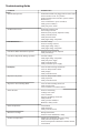
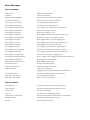
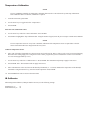
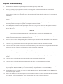
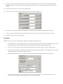
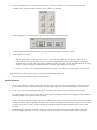
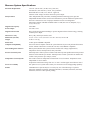
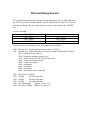
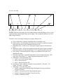
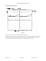
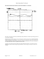
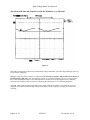
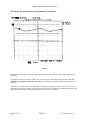
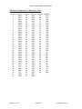
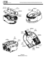
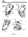
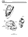
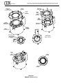
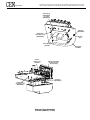
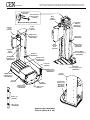
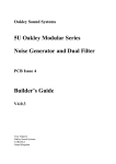
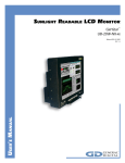
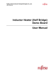
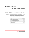
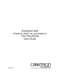
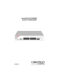
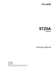
1
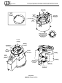
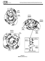
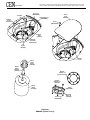
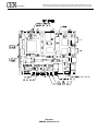
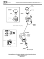
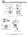
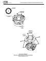
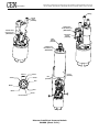
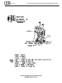
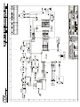
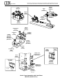
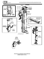
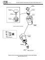
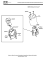
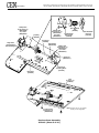
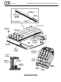
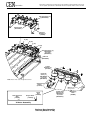
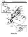
CEMs modular family of microwave synthesis instrumentation begins with the Discover module for focused synthesis. The Explorer module expands the capabilities of the Discover module with high throughput reaction handling capabilities. The Explorer module installs on top of the Discover module. The Voyager module, a ßow-through reaction system, further expands the capabilities of the Discover module for rapidly synthesizing larger quantities of compounds for laboratory scale-up. Methods developed on the Discover or the Explorer transfer directly to the Voyager. The Voyager module also installs on top of the Discover module. Introduction The CEM Focused Microwave Synthesis System, Model Discover, is designed to enhance the ability to perform chemical reactions under controlled conditions on a laboratory scale. The CEM Automated Synthesis System, Model Explorer, is designed to add automated reaction handling capabilities to the Discover instrument. The Focused Microwave family of instruments enhance the ability to perform chemical reactions under controlled conditions on a laboratory scale. These systems facilitate either homogeneous or heterogeneous solution phase chemistry, solid phase chemistry or chemistry conducted on solid supports. They accommodate vessels ranging in volume from 5mL to 125mL for reactions performed under atmospheric conditions and 10mL and 80mL sealed vessels for reactions performed at elevated temperatures and pressures. Primary uses of the Explorer and/or Discover are in the discovery and lead optimization phases of the drug development process. Microwave energy is applied to the vessel contents (reactants, catalysts, salts, solvents and/or solid supports) to accelerate the chemical reaction. The microwave absorption properties of some liquid and solid materials, due to their polar and ionic characteristics, have the capability to signiÞcantly enhance chemical reactions relative to traditional energy application (heating) techniques. The microwave interaction properties with the reactants, intermediates, catalysts, solid supports and salts provide unique opportunities for the synthetic chemist. The Discover System consists of: A continuous microwave power delivery system with operator selectable power output from 0 - 300 watts (+/- 30 watts) programmable in 3-watt increments. A self-adjusting, single mode microwave cavity that is manually accessed via one of two attenuator ports (both ports are included) A 4-line x 20-character vacuum ßuorescent display with alphanumeric keypad and on-board computer for programming and operational control of the system. The memory will store and recall up to 20 methods 3 safety interlocks and an interlock monitoring system to prevent microwave emission when the attenuator port is not properly installed Two serial ports for computer interface and optional feature connections An ethernet port for network connection (optional conÞguration) An infrared Temperature Control System A pressure sensor for feedback control of the system A magnetic stirrer A coolinhg system to decrease the temperature of a 20mL solution in a 10mL Pyrex reaction vessel from approximately 150 ºC to 40 ºC in less than 20 seconds The Explorer Automation Module consists of: A Discover Module A software control package for programming and data management An X, Y table that delivers 10 mL reaction vessels to the microwave chamber Four (4) independent Vessel Racks with six (6) positions A drive motor and table slide in each vessel rack, permitting independent movement and loading A Z-axis mechanism that integrates a reaction vessel gripper to manipulate vessels An attenuator locking mechanism to seal the reaction vessels in the microwave system An external controller (computer) (optional purchase from CEM Corporation) Both systems include application software and an accessory kit. Optional features include: Fiber Optic Temperature Control System This optional temperature control system, for use with large volume, open vessel applications, uses a Þber optic temperature probe for temperature measurement and control of the vessel contents. It is used only with manual operation of the Discover system. The Þber optic probe is an invasive measurement technique and thus requires access to the reaction container from the external environment. It connects to the instrument through the second serial port at the rear of the instrument. When connected, the Discover system automatically detects the temperature sensor and defaults to use this sensor for temperature measurement and control. Temperature is programmable from 25 - 250 ºC. Standard Attenuator (541125) Open Vessel Attenuator (541130) WARNING This instrument utilizes high voltages and microwave radiation. Only technicians trained in repair and maintenance of high voltage and microwave power systems should perform instrument service and repair. WARNING Proper precautions must be taken to avoid contact with solvents or solvent vapors. Protective gear should be worn as outlined in the users safety program for hazardous materials and the reagent manufacturers material safety data sheet. Refer to these guidelines for proper handling and disposal of reagents. Routine Maintenance and Cleaning Interlocks Weekly, examine the cavity edge and attenuator interlocks to verify that they are clean and working properly. Cavity Weekly, wipe the cavity liner with an alcohol wipe or equivalent. Lubrication Proper lubrication for the Explorer module is CEM part number BR199188 Superlube (a synthetic grease containing Teßon) Microwave Leakage Measurement The attenuator and cavity of the Discover are durable and are designed for reliable operation under severe laboratory conditions. External radiation checks are performed on the Discover System at several points in the manufacturing process, ensuring that leakage from the Þnished instrument is only a fraction of that allowed by U.S. law (5 mW/cm2). The attenuator is equipped with a safety interlock system to stop the generation of microwave energy when the attenuator is opened or ajar. If the interlock system fails, a monitoring mechanism will blow the fuse(s) through which power is supplied to the magnetron, rendering the microwave power system inoperable. To verify that seals and interlocks are working properly, the Discover System should be tested periodically for microwave leakage. Use the following procedure to measure microwave leakage: 1. Create a standard method using 300 watts of power, 2 minutes run time, 95 C temperature set-point and 1-minute hold 2. 3. 4. 5. Place a round bottom ßask containing 50mL of demonized water into the cavity. Attach the attenuator with RF stub to accept a 24/40 ground glass joint. Load the created method and press Start to begin the method. Use a suitable RF Þeld strength meter (microwave detector) such as the Holaday Model HI-1500. Slowly move the RF probe around the attenuator perimeter and around the fan grills to check for microwave leakage. Check leakage around the cavity lid. time. NOTE CEM does not recommend use of meters available in electronics stores because they are prone to give erroneous readings and lack the necessary sensitivity to properly test an instrument for microwave leakage. The U.S. Government deÞnes excessive microwave leakage as 5 mW/cm2. If the instrument shows excessive microwave leakage, do not attempt further operation. Contact the CEM Corporation Service Department or the local CEM subsidiary or distributor for further instructions. Microwave Power Measurement Use the following procedure to determine actual power output in watts for a 300-watt setting. 1. 2. 3. 4. 5. 6. 7. 8. 9. 10. 11. 12. 13. Remove the 10mL attenuator (access) port. Place the Teßon spacer on the ßoor of the cavity. Create a power and time method using 300 watts of power and a run time of 60 seconds. Place 100 mL of ambient temperature (18-22 °C) deionized water and a stirring bar, if available, in a 100 mL round bottom ßask (with a ground glass joint of a size less than or equal to 24/40). Using a thermometer with 0.1 °C gradations. Stir the water for at least 15 seconds, then measure and record the initial water temperature, Ti. Ensure that the thermometer is immersed to its indicated immersion line prior to reading the temperature. Remove the thermometer from the ßask. Carefully place the ßask into the cavity. Attach the attenuator with RF stub to accept a 24/40 ground glass joint. Load the method created in step 3, and press Start to begin the method. At the end of the programmed time (60 sec), stir the water thoroughly for 10 seconds, then quickly measure and record the peak temperature reading. This is the Þnal temperature, Tf. The microwave power output is calculated as follows: Power in Watts = 6.97 (Tf Ti) If the measured power is below 270W, repeat the microwave power measurement. If the power remains less than 270W, the instrument is not producing adequate microwave power at the 300W selection. Remove the Teßon spacer from the ßoor of the cavity. Install the 10mL attenuator (access) port. If the instrument is not producing sufÞcient wattage, refer to the Troubleshooting Guide in this manual. Instrument Cold Start While depressing the START key, position the instrument power switch in the on position. Master Password Login: Administrator Password: cemdiscover Troubleshooting Guide Condition Possible Cause No Microwave Power Instrument attenuator ajar Zero wattage selected Interlock(s) not properly adjusted or faulty Faulty controller board Faulty thermal switch Faulty high voltage component Instrument Inoperative Low Microwave Power Fuse Blows When Attenuator Is Opened Fuse Blows Repeatedly During Operation No Display Inoperative Keyboard Inoperative Vessel Stirring Motor Erratic Pressure Erratic Temperature Microwave Leakage No Rise in Temperature Instrument modules not plugged into electrical outlet Power switches not in on position Proper instrument not selected in system software Blown fuse(s) Loose connections to power switch(es) Faulty power switch(es) Faulty DC power switch Low line voltage Incorrect wattage selected Faulty high voltage relay(s) Faulty high voltage component Interlock(s) not properly adjusted Faulty interlock(s) Low line voltage Faulty high voltage component Faulty DC power supply Faulty controller board Faulty continuous power supply Loose or broken wiring connections Loose or faulty interface cable Faulty display Faulty controller board Loose or faulty interface cable Faulty keyboard Faulty controller board Loose or broken stirring motor belt Faulty stirring motor Loose connector on controller board Incorrect A/D setting Leakage from vessel Loose connector Improper grounding connection Faulty load cell Faulty pressure transducer Blocked or faulty needle Lens blocked Faulty IR sensor Faulty controller board Damaged attenuator Pressure sensor unattached or faulty Sample does not absorb microwave energy Faulty infrared temperature sensor Incorrect temperature calibration constants entered Lens blocked Error Messages Discover Module Display Error: Display is not functioning Temperature Not Calibrated: Temperature Device has not been calibrated A/D Error: Pressure Not Calibrated: Power Supply Low Voltage: Power Supply High Voltage: Power Supply Comm Timeout: Power Supply Shorted RTD: Power Supply Open RTD: Power Supply Temperature: Power Supply Sec. Max Range: Power Supply Hi Control: Power Supply Lo Control: Power Supply Delta Temp: Power Supply RunAway: Power Supply PS Comm Failure: Power Supply PS Not OFF: Power Supply Sec. Min Range: Power Supply Thermal Overload: Power Supply Ground Error: Power Supply No Microwaves: Pressure Drop Error: Temperature Drop Error: No Pressure Error: Excess Pressure Error: Fiber Optic Timeout Error: Fiber Optic Probe Failure: A/D is not functioning Pressure Device has not been calibrated Line Voltage Below minimum level Line Voltage Above maximum level Power Supply Lost communication with Discover RTD in Power Supply is shorted RTD in Power Supply is open Power Supply Heat Sink temperature too high (65 °C) Secondary Current in Power Supply too high Power Supply unable to generate enough power Power Supply unable to generating too much power No temperature rise detected in Heat Sink Power Supply could not adjust to required power Discover lost communication with Power Supply Power Supply is applying power when should be off Secondary current in Power Supply too low No AC voltage to Power Supply (Thermal switch or Interlock) Power Supply lost Earth Ground Power Supply could not start Pressure Dropped too rapidly Temperature Dropped too rapidly No pressure was detected (Plugged Needle, Defective Transducer, Bad Calibration) Pressure Exceeded Maximum allowed (300 psi) Lost Communication with Fiso Probe error received form Fiso Explorer Module Vessel Missing: Vessel was not detected in required rack position Vessel Stuck: Vessel was not released Vessel Dropped: Time out: Missed Z Axis Limit Switch: Bad Start Location: Low Air: Vessel was dropped during insertion or removal Axis did not go to commanded position Bottom Z Axis switch not actuated while at lock position Z Axis not at home when move began Vessel clamp not operating WARNING Disconnect the instrument from the AC power source prior to performing any service procedure. Prior to any troubleshooting or service procedures in the high voltage section or area, bridge the contacts of the high voltage capacitor using the metal shaft of a well-insulated screwdriver to discharge the residual voltage in the capacitor. This will prevent exposure to high voltage discharge during troubleshooting or service. Before replacing the high voltage plate assembly after any service procedure involving the microwave generating components, visually check the magnetron, transformers, triac, and high voltage capacitor to ensure that the electrical connections are secure. Any service to or inspection of the Discover System that requires removal of the power supply assembly or replacement of components in the interlock mechanism, microwave generation system, or microwave transmission system should be followed by a microwave leakage measurement to verify that leakage is less than 5 mW/cm2. Cavity Liner Cleaning/Replacement The Discover System is equipped with a replaceable cavity liner positioned inside the cavity of the instrument. It protects the temperature sensor from debris in case of a vessel failure. If a vessel failure occurs, the cavity liner should be removed and cleaned or replaced if it is damaged. WARNING Proper precautions must be taken to avoid contact with solvents or solvent vapors. Protective gear should be worn as outlined in the users safety program for hazardous materials and the reagent manufacturers material safety data sheet. Refer to these guidelines for proper handling and disposal of reagents. 1. Carefully remove the cavity liner by grasping it and pulling it up and out of the cavity, using caution to prevent spillage through the opening. 2. Rinse the liner with an appropriate solvent to remove all debris. 3. Inspect the liner for damage. If the liner is damaged, especially the lens area, replace the liner. 4. Install the liner into the cavity, ensuring that the spout is positioned into the spill channel. Note: If the liner is not seated properly, the attenuator cannot be installed properly. 4. If the cavity liner is replaced, calibrate the temperature sensor as outlined in the System Setup section of this manual. Cavity Liner Spill Tray Cleaning Spill Tray Adjustment of Interlock Switches Temperature Calibration NOTE If a new E-PROM is installed, the temperature calibration data must be re-entered into the system setup information. If the calibration data is not known, calibration is required. 1. From the main menu, press EDIT. 2. Use the arrow keys to toggle and select Temperature. 3. Press ENTER. Enter Previous Calibration Values 4. Use the arrow keys and select Enter Calibration. Press ENTER. 5. Press EDIT to highlight the slope calibration data. Using the numeric keypad, enter the previous slope constant. Press ENTER. NOTE If a new temperature sensor or cavity liner is installed, calibration of the temperature sensor is required due to the difference between the IR lenses designed into the cavity liner. Calibrate Temperature Sensor 6. Place 3mL of dimethyl formamide in a 10mL reaction vessel with a stir bar. Place a cloth over the vessel to prevent splattering. Disconnect the cooling supply line. Using Power-Time control, program the system to irradiate the reaction vessel at 300W for 30 seconds (approximately 150 C). 7. Use the arrow keys and select Calibrate Device. Press ENTER. The instrument will prompt to apply a heat source. 8. Press ENTER. Note: The instrument will not apply microwaves. 9. Place a thermometer in the vessel and stir the dimethyl formamide (2 - 3 seconds). Measure the temperature of the dimethyl formamide. Using the numeric keys, enter the actual temperature. Press ENTER. 10. Press HOME three times to return to the main menu. IR Calibrator When using an IR calibrator (CEM part number 541165), use the following settings: IR Emissivity E = .75 IR Transmissivity T = .70 Pressure Calibration NOTE If a new E-PROM is installed, the pressure calibration data must be re-entered into the system setup information. If the calibration data is not known, calibration is required. 1. From the main menu, press EDIT. 2. Use the arrow keys to toggle and select Pressure. 3. Press ENTER. Enter Previous Calibration Values 4. Use the arrow key(s) and select Enter Calibration. Press ENTER. 5. Press EDIT to highlight the slope calibration data. Using the numeric keypad, enter the previous value for the slope of the pressure curve. Press ENTER. The instrument highlights the intercept data. 6. Using the numeric keypad, enter the previous value for the intercept of the pressure curve. Press the ENTER key. NOTE If a new temperature sensor or cavity liner is installed, calibration of the temperature sensor is required. Calibrate Pressure Sensor 7. Use the arrow key(s) and select Calibrate Device. Press ENTER. 8. Upon the Zero Pressure prompt, ensure that there is no pressure applied to the pressure assembly. Press ENTER. 9. Upon the Apply Pressure prompt, apply a pressure source with a known pressure value to the pressure sensor assembly (maximum pressure 300 psi or 21 bar). Using the numeric keys, enter the applied pressure value. Press ENTER. 18. Press HOME to return to the main menu. Explorer Module Assembly 1. Place the Discover module in an appropriate position as outlined previously in this manual. 2. Remove the top cover lid from the Discover module by pressing lightly on the secure tab at the rear center of the lid while slightly lifting and pulling backward on the lid to disengage the front insert tabs. 3. Remove the Þve (5) screws securing the top cover of the Discover module (two in front, one for the condenser location and two in the rear of the cover). Discard the screws, but retain the washers from the screws in the rear of the instrument for reinstallation. 4. Install the Explorer automation module attenuator. Turn the attenuator clockwise sufÞciently for the switches to lock into position. 5. Place the Explorer automation module support plate on the Discover module, ensuring that the plate is positioned as far forward as possible to permit proper alignment of the Explorer automation module. 6. Secure the Explorer automation module support plate with the Þve (5) long screws included with the Explorer automation module, tightening the screw in the center of the plate Þrst. Install the washers retained in step 3 on the two screws installed in the rear of the cover. CAUTION Never lift the Explorer automation module by the vertical arm or movable table that holds the racks. 7. Lift the Explorer automation module by the base and place it on the support plate. Loosely install one of the screws provided with the Explorer automation module in the exposed screw hole. 8. Remove the screws and two white positioning braces from the Explorer automation module. Reinstall the screws. Discard the positioning braces. 9. Connect the 7-pin pressure sensor connector to the 7-pin electrical connector in the rear of the Discover module. 10. Connect the serial cable (cream colored) between the bottom bottom 9-pin male connector of the Explorer automation module and the right serial port (comm port 2) of the Discover module (facing back of instrument). 11. Place the computer on a suitable work area preferably on the right side of the instrument for ease of operation. 12. Connect the serial cable (gray) between the computer and the left serial port (comm port 1) of the Discover module). 13. Plug the power cord of the Computer into the electrical outlet and boot the computer, ensuring the operating system loads properly. 14. Connect the power cord to the Discover module and plug it into an appropriate electrical outlet. 15. Connect the power cord to the Explorer automation module and plug it into an appropriate electrical outlet. 16. Position the power switches of both the Discover module and the Explorer automation module in the on position. 17. Using the keyboard on the Discover module, press the EDIT key. Press the right arrow key twi times. The screen will display System Options. Press the ENTER key. The screen will display Peripheral Settings. Press the ENTER key. 18. Press the right arrow key two times. The screen will display Mode - Explorer. Press the ENTER key. Press the HOME key. The screen will display Explorer. 19. Double click the Discover icon on the computer screen. The instrument software requires a user name. Once the User Name screen appears, use the keyboard and type cem as the user name. Do not enter a password at this time. 20. The Instrument Setup will be displayed on the Computer screen followed by the Automation Setup screen. 21. From the Automation Setup screen, highlight Instrument and select Explorer Setup. 22. Locate the Absolute Move section in the upper left side of the Explorer Setup screen. The Ex_Sys_Status should read 0, indicating that the instrument components are communicating properly. Note: If the Ex_Sys_Status reads 20, the instrument is not communicating properly. Turn off the computer, unplug all instrument modules, replug all modules, and check the serial port connections between the instrument and the computer. If the Ex_Sys_Status continues to read 20, contact CEM. 23. Locate the Home section in the top left side of the Explorer Setup screen. Click the All key. The Explorer automation module arm will raise, the table will move to the right, and the racks will move in and out until all have reached the home position. 24. Remove the plastic protective cover from the gripper Þngers. 25. Locate the Z Axis information in the upper right corner of the Explorer Setup screen. 26. Click the R (read) button to read the instrument Z axis information. Wait until the data is displayed in all windows. 27. Locate Atten Grip (attenuator grip), and click the associated GO button. The pressure sensor assembly will lower. 28. Align the explorer module as outlined below: IntelliVent Note: Proceed to the next page for alignment if instrument is equipped with direct pressure. a. Using minimal force, close the gripper Þngers. If necessary, adjust the position of the Explorer automation module so that the gripper Þngers are centered around the port of the attenuator and reach the attenuator simultaneously. b. Locate Up in the Z Axis information, and click the associated GO button to raise the pressure sensor assembly. c. Open the pressure sensor assembly gripper Þngers. Install (push) the alignment/calibration tool, supplied with the Explorer automation module, into the pressure sensor assembly. d. Install and tighten the two screws securing the left side of the Explorer automation module to the support plate. 2000 e. Locate the Absolute Move section of the screen. Select (left mouse click) the Y axis. Position the curser in the Increment box. Using the computer keyboard, enter 2000. Press ENTER. e. Locate the Absolute Move section of the screen. Select (left mouse click) the Y axis. Position the curser in the Increment box. Using the computer keyboard, enter 2000. Press ENTER. f. Install and tighten the screw securing the right side of the Explorer automation module. g. Locate the Home information and click the All button to home the Explorer automation module. h. Verify alighment. as follows: 1. With the gripper Þngers completely opened, locate Atten Grip (attenuator grip), and click the associated GO button. The pressure sensor assembly will lower. Close the gripper Þngers to ensure that the Þngers will clamp the attenuator at the same time. The gripper Þngers should be completely parallel, vertically and horizontally. If necessary, carefully reposition the Explorer automation module so that the gripper Þngers will be aligned. 2. Locate Up in the Z Axis information and click the associated GO button to raise the pressure sensor assembly. Note: If necessary, repeat the above steps to verify the automation module alignment. i. Proceed to step 29 to continue Explorer module assembly. Direct Pressure a. Using a small screwdriver or small spatula, apply minimual force required to close the gripper Þngers. If necessary, adjust the position of the Explorer automation module so that the gripper Þngers are centered around the port of the attenuator. b. Locate Up in the Z Axis information, and click the associated GO button to raise the pressure sensor assembly. c. Open the pressure sensor assembly gripper Þngers. Install (push) the alignment/calibration tool, supplied with the Explorer automation module, into the pressure sensor assembly. d. Locate Atten Drop (attenuator drop) in the Z axis information, and click the associated GO button. The pressure sensor assembly will lower, and the alignment tool will enter the attenuator. The alignment tool should be centered as it enters the attenuator. If necessary, carefully reposition the Explorer automation module so that the alignment tool is centered in the attenuator. e. Install and slightly tighten the two screws securing the left side of the Explorer automation module to the support plate. 2000 f. Locate the Absolute Move section of the screen. Position the curser in the Increment box. Using the computer keyboard enter 2000. Press ENTER g. Install and slightly tighten the screw securing the right side of the Explorer automation module. i. Locate the Zero Axis information and select (left mouse click) the Y button. j. Locate Up in the Z Axis information and click the associated GO button to raise the pressure sensor assembly. k. Remove the alignment tool from the pressure sensor assembly. l. With the gripper Þngers completely opened, locate Atten Grip (attenuator grip), and click the associated GO button. The pressure sensor assembly will lower. Close the gripper Þngers to ensure that the Þngers will clamp the attenuator at the same time. The gripper Þngers should be completely parallel, vertically and horizontally. If necessary, carefully reposition the Explorer automation module so that the gripper Þngers will be aligned. m. Locate Up in the Z Axis information and click the associated GO button to raise the pressure sensor assembly. Note: If necessary, repeat the above steps to verify the automation module alignment. n. Complete the tightening of the two screws securing the left side of the Explorer automation module to the support plate. o. Locate the Absolute Move section of the screen. Position the curser in the Increment box. Using the computer keyboard enter 2000. Press ENTER. p. Complete the tightening of the screw securing the right side of the Explorer automation module. q. Locate the Zero Axis information and select (left mouse click) the Y button. 29. Install the vessel racks into the tagble with the rounded ends toward the front of the instrument. 30. VerÞy In/Out rack adjustment as follows. a. Locate the vial position table in the lower right side of the Explorer Setup screen. b. Click the Read All button to read the vial position information. Wait until all data is displayed in the windows. c. Select (click) the small circle for vial position #A1. d. Select (click) ABCD Position (In/Out). e. Locate Rack Grip in the Z Axis information and click the associated GO button. The assembly will lower. The gripper Þngers should be centered on the lip of the rack position A-1 from an in/out perspective. f. If necessary, adjust the position of the Þngers by adjusting the value for position A1. Highlight the current value and type the new value, adjusting the value in increments of 10 (+10 to move the rack out or 10 to move the rack in). g. Click the GO button in the table portion of the screen. The Þngers will move to the new position. h. Continue adjusting the value in increments of 10 until the gripper Þngers are centered on the lip of the rack. i. If an adjustment was made to ABCD Position in A-1, enter that value into the ABCD Offset (In/Out), and select (left mouse click) W to write the value to the instrument memory. 31. VerÞy Left/Right rack adjustment as follows. a. Locate the vial position table in the lower right side of the Explorer Setup screen. b. Click the Read All button to read the vial position infomation. Wait until all data is displayed in the windows. c. Select (left mouse click) the small circle for vial position #A1. d. Select (left mouse click) Left/Right Position. e. Locate Rack Grip in the Z Axis information and click the associated GO button. The assembly will lower. The gripper Þngers should be centered on the lip of the rack position A-1 from a left/right perspective. f. If necessary, adjust the position of the Þngers by adjusting the value for position A1. Highlight the current value and type the new value, adjusting the value in increments of 10 (+10 to move the rack to the left or 10 to move the rack to the right). g. Click the GO button in the table portion of the screen. The Þngers will move to the new position. h. Continue adjusting the value in increments of 10 until the gripper Þngers are centered on the lip of the rack. i. If an adjustment was made to the Left/Right Position in A-1, increase each rack position left/right value by the same amount and press (left mouse click) W to write each value to the instrument memory. j. Repeat the above steps to verify the left/right alignment of racks B, C and D. 32. Connect the air regulator to the user supplied air source (clear compressed air or nitrogen). NOTE The air supply must e capable of delivering 30 psi. 33. Connect the 12 length of tubing supplied with the Explorer automation module getween the connector on the right side of the Discover module (facing back of instrument) and one of the two connectors on the manifold of the Explorer module. 34. Connect the long length of tubing between the second connector on the manifold of the Explorer module and the air regulator. 35. Set the air regulator to 30 psi. 36. Verify the proper operation of the gripper Þnger switches as follows. a. Refer to the Absolute Move section of the Explorer Setup screen. The Clamp conÞguration should read 3 with the gripper Þngers opened. b. Manually close the gripper Þngers. The Clamp conÞguration should read 0 with the Þngers closed. c. Manually place and hold a vial in the gripper Þngers. The Clamp conÞguration should read 2 while the vial is secure. 37. Ensure that all three (3) screws securing the Explorer automation module to the support plate are tightened securely. 38. Place a vial in position #1 of the racks. . Verify that the pressure sensor assembly properly loads vials into the attenuator and returns vials to the racks as follows: a. Place vials in positions 1, 6 and 24 of the racks. Click the All button in the Home section of the Explorer Setup screen to ensure that all components move to their home positions. b. Locate the Vessel Control section in the lower left corner of the Explorer Setup screen. c. Using the keyboard, type 1 into the Stage Position entry area. d. Click the Load Vessel button. The rack will move into position over the attenuator port. The Z axis arm will move down and the gripper Þngers will grasp and lift the vial from rack position #1. The rack will move back into the home position. The Z axis arm will them move down and position the vial into the attenuator port. It will then move back into its home position. e. Click the Return Vessel button. The pressure sensor assembly will lift the vial from the attenuator and return it to position #1 of the rack assembly. f. Observe the movement of the vial into the attenuator and into the rack, ensuring that the vial is lifted properly by the gripper Þngers and that the vial is centered as it enters the attenuator and rack position. Refer to the previous instructions and make any necessary adjustments. f. Repeat steps c through f for position #6 and position #24. 39. Create a method and perform a complete cycle test with vials in all 24 positions to ensure proper operation. Component Replacement Infrared Sensor Assembly 1. Position the Discover System power switch in the off position and disconnect the power cord from the electrical source. 2. Facing the instrument, position it on its left side. 3. Remove the stirrer cover (162620) by removing the screw (BR128200) that secures the cover, then slightly tilting the cover away from the screw tab and lifting it outward to disengage the insert tabs securing the cover. 4. Using an Allen wrench, loosen the setscrew securing the IR assembly sensor head (541035) to the microwave cavity RF stub. 5. Using a downward force, pull the sensor head off of the RF stub. The sensor head will remain connected to the IR assembly cable. 6. Reposition the Discover upright onto its base. 7. Remove the top cover lid (162710) by pressing lightly on the secure tab at the rear center of the lid while slightly lifting and pulling backward on the lid to disengage the fronts insert tabs. 8. Remove the four (4) screws securing the top cover assembly (660929). 9. Remove the two (2) screws (BR196077) securing the IR assembly (541035) to the base of the instrument. 10. Disconnect the IR assembly wiring from the CPU board by removing the 4-pin connector at the J6 location and the ground connector at the J4 location on the board. 11. Carefully feed the IR assembly cable up through the access hole in the bottom of instrument. Remove the IR assembly wiring from the wiring harness bundle. 12. Lift the IR assembly (cable, sensor head, calibration box and wiring harness) out of the instrument. 13. Carefully route the new IR assembly cable and sensor head gently through the access port in the base of the instrument. 14. Secure the IR assembly calibration box to the base with two screws. Tighten the screws until snug. Note: To prevent component damage, do not overtighten the screws. 15. Route the IR assembly wiring harness to the CPU board and connect the 4-pin connector at the J6 location and the ground connector at the J4 pin location. 16. Facing the instrument, position it on its left side. 17. Using steady, gentle pressure, install the IR assembly sensor head onto the RF stub until it stops. Using an Allen wrench, tighten the setscrew. Note: Do not overtighten the setscrew. 18. Install the new stirrer cover (162620) by tilting it slightly away from the screw tab, engaging the insert tabs, and then sliding it in until it stops. Install the screw that secures the cover (BR128200) and tighten it until it is snug. 19. Position the instrument upright on its base. 20. Install the top cover assembly (660929) and, using the four (4) screws, secure it to the base. 21. Install the Top Cover Lid (162710) by engaging the front insert tabs and sliding the lid forward until it stops. Lower the lid to engage the secure tab at the rear center of the lid until it snaps into place. 22. Plug the power cord into the electrical outlet. Position the on/off switch in the on position. 27. Calibrate the IR assembly using the calibration procedures outlined in this manual. Stirrer Motor Belt 1. Position the Discover System power switch in the off position and disconnect the power cord from the electrical source. 2. Facing the instrument, position it on its left side. 3. Remove the stirrer cover (162620) by removing the screw (BR128200) that secures the cover, then slightly tilting the cover away from the screw tab and lifting it outward to disengage the insert tabs securing the cover. 4. Using a wrench, disconnect the Þtting on the cooling gas inlet tubing and remove the tubing from the cavity assembly. 5. Using an Allen wrench, loosen the setscrew securing the IR assembly sensor head (541035) to the microwave cavity RF stub. 6. Using a downward force, pull the sensor head off of the RF stub. The sensor head will remain connected to the IR assembly cable. 7. Loosen the two screws (BR196439) with star washers (BR198650) that secure the stirrer motor (314105) to the instrument base. 8. Slide the stirrer motor pulley assembly forward, permitting slack in the belt. 9. Carefully remove the loose belt from the groove of the stirrer plate (162455). Remove the stirrer motor belt. 10. Position the new belt around the stirrer motor pulley assembly and into the groove of the stirrer plate (162455). 11. Move the stirrer motor pulley assembly backward with steady, even pressure until the belt feels tight. 12. Tighten the two screws (BR196439) with star washers (BR198650), securing the stirrer motor (314105) to the instrument base. 13. Test the belt tension by turning the stirrer plate manually. If binding occurs or the stirrer plate does not turn freely, slightly loosen one of the two screws securing the stirrer motor pulley assembly and move the assembly slightly forward. Tighten the screw and recheck the belt tension. 14. Using steady, gentle pressure, slide the IR assembly sensor head onto the RF stub.. 15. Using an Allen wrench, tighten the setscrew until snug. Do not over tighten the setscrew. 16. Connect the cooling gas inlet tubing to the cavity assembly and, using a wrench, tighten the Þtting until snug. 17. Install the stirrer cover (162620) by tilting it slightly away from the screw tab, engaging the insert tabs, and then sliding it in until it stops. Install the screw that secures the cover (BR128200) and tighten it until it is snug. 18. Position the instrument upright on its base. 19. Plug the power cord into the electrical outlet. Position the on/off switch in the on position. Stirrer Motor 1. Position the Discover System power switch in the off position and disconnect the power cord from the electrical source. 2. Facing the instrument, position it on its left side. 3. Remove the stirrer cover (162620) by removing the screw (BR128200) that secures the cover, then slightly tilting the cover away from the screw tab and lifting it outward to disengage the insert tabs securing the cover. 4. Using a wrench, disconnect the Þtting on the cooling gas inlet tubing and remove the tubing from the cavity assembly. 5. Using an Allen wrench, loosen the setscrew securing the IR assembly sensor head (541035) to the microwave cavity RF stub. 6. Using a downward force, pull the sensor head off of the RF stub. The sensor head will remain connected to the IR assembly cable. 7. Loosen the two screws (BR196439) with star washers (BR198650) that secure the stirrer motor (314105) to the instrument base. 8. Slide the stirrer motor pulley assembly forward, permitting slack in the belt. 9. Carefully remove the loose belt from the groove of the stirrer plate (162455). Remove the stirrer motor belt. 10. Remove the two Allen screws (162715) securing the stirrer motor pulley to the stirrer motor adapter (134720), and remove the stirrer motor pulley. 11. Remove the top cover lid (162710) by pressing lightly on the secure tab at the rear center of the lid while slightly lifting and pulling backward on the lid to disengage the fronts insert tabs. 12. Remove the four (4) screws securing the top cover assembly (660929). 13. Disconnect the stirrer motor assembly from the CPU board by disconnecting the 2-pin connector at pin location J8. Remove the stirrer motor wiring from the wiring harness. 14. Position the instrument upright on its base. 15. Remove the stirrer motor. 16. Position the new stirrer motor assembly through the access in the instrument base. 17. Reposition the instrument upright on its base and loosely install the screws and star washers. 18. Install the stirrer motor pulley onto the stirrer motor adapter, and secue it with two Allen screws. 19. Position the belt around the stirrer motor pulley assembly and into the groove of the stirrer plate (162455). 20. Tighten the two screws (BR196439) with star washers (BR198650), securing the stirrer motor (314105) to the instrument base. 21. Test the belt tension by turning the stirrer plate manually. If binding occurs or the stirrer plate does not turn freely, slightly loosen one of the two screws securing the stirrer motor pulley assembly and move the assembly slightly forward. Tighten the screw and recheck the belt tension. 22. Position the instrument upright on its base. 23. Install the top cover assembly (660929) and, using the four (4) screws, secure it to the base. 24. Install the Top Cover Lid (162710) by engaging the front insert tabs and sliding the lid forward until it stops. Lower the lid to engage the secure tab at the rear center of the lid until it snaps into place. 25. Plug the power cord into the electrical outlet. Position the on/off switch in the on position. Cooling Solenoid 1. Position the Discover System power switch in the off position and disconnect the power cord from the electrical source. 2. Remove the top cover lid (162710) by pressing lightly on the secure tab at the rear center of the lid while slightly lifting and pulling backward on the lid to disengage the front insert tabs. 3. Remove the four (4) screws securing the top cover assembly (660929). 4. Disconnect the cooling solenoid assembly (P/N 162550) from the solenoid wiring harness by disconnecting the wiring at the two Faston plugs (BR109931). 5. Facing the instrument, position it on its left side. 6. Disconnect the cooling gas inlet tubing. 7. Remove the cooling solenoid cover (162615) by removing the three screws (BR128200) that secure the cover. The cover can then be removed by pulling it gently away from the base. 8. Disconnect the internal cooling tube from the cooling solenoid. 9. Slide the cooling solenoid from its compartment in the base. 10. Connect the internal cooling gas tube to the new cooling solenoid. 11. Connect the two Faston plugs (BR109931) on the cooling solenoid assembly to the wiring harness. 12. Slide the cooling solenoid back into its compartment, using caution to prevent crimping the wiring connector or inlet cooling gas tubing. 13. Install the cooling solenoid cover and secure it to the instrument base with three screws. 14. Position the instrument upright on its base. 15. Install the top cover assembly (660929) and, using the four (4) screws, secure it to the base. 16. Install the top cover lid (162710) by engaging the front insert tabs and sliding the lid forward until it stops. Lower the lid to engage the secure tab at the rear center of the lid until it snaps into place. 17. Plug the power cord into the electrical outlet. Position the on/off switch in the on position. High Voltage Supply 1. Position the Discover System power switch in the off position and disconnect the power cord from the electrical source. 2. Remove the top cover lid (162710) by pressing lightly on the secure tab at the rear center of the lid while slightly lifting and pulling backward on the lid to disengage the fronts insert tabs. 3. Remove the four (4) screws securing the top cover assembly (660929). 4. Using an Allen wrench, remove the two Allen screws securing the right interlock switch assembly to the top microwave choke plate. Use extreme caution to prevent damage to the switch assembly wiring, which is still connected to the assembly. 5. Slide the right interlock pin out of the microwave cavity choke plate assembly. 6. Remove the AC power connector from the high voltage power supply located on the front left corner of the top cover of the HV supply. 7. Using an Allen wrench, remove the two Allen screws securing the communications connector located on the front right corner of the top of the HV Supply. Remove the connector. 8. Using an 11/32 hex nut driver, remove the grounding strap connecting the HVsupply cover to the top of the waveguide. 9. Using a Phillips screwdriver, remove the four screws securing the HV supply to the instrument base. Note: Eight (8) screws are visible on the top of the HV supply. The four (4) screws securing the supply to the base are located closest to the outside of the supply. The 4 screws located toward the center of the supply secure the internal boards to the supply assembly and should not be removed. 10. Remove the two wires, which connect the HV supply cooling fan to the CPU board, from the HV supply cooling fan. Route the wires through the access in the HVsupply cover located at the right rear of the instrument. Remove the two wires, which connect the magnetron cooling fan to the CPU board, from the magnetron cooling fan. Route the wires through the access in the magnetron cooling fan cover located at the left rear of the instrument. Label each wire for its proper installed position. 11. Using a Phillips screwdriver, remove the two screws securing the magnetron cooling fan cover located at the left rear of the instrument. Remove the cover. CAUTION Ensure the instrument power cord is disconnected. Failure to disconnect the power cord could lead to extreme electrical shock. Only technicians trained in high voltage component repair should attempt this repair. 12. Locate the two HV wires (one black, one white) connecting the HV supply to the magnetron. Using a pair of needlenose pliers, remove these wires from the magnetron by pulling the wiring connectors from the magnetron wiring tabs. 13. Remove the HV ground strap connecting the internal supply to the waveguide. This strap is located below the HV supply cover ground strap on the waveguide. Note: There are three ground straps located on the same tap. 14. Remove the HV supply assembly from the instrument base by grasping the front and back of the supply and tilting it toward the back of the instrument while lifting it upward. 15. Install the new HV supply on the instrument base. 16. Connect the HV wires to the magnetron (white wire on top tap, black on bottom tap). 17. Connect the two ground straps to the waveguide tap. Using an 11/32 hex nut driver, tighten the hex nut. 18. Install the magnetron cooling fan cover and secure it with the two screws. 19. Connect the two wires extending from the CPU board to the magnetron cooling fan. 20. Connect the two wires extending from the CPU board to the HV supply cooling fan. 21. Secure the HV supply to the instrument base by installing the four screws into HV supply cover. 22. Install the communications connector in the right front corner of the HV supply. Install the two Allen screws to secure the connector. 23. Connect the AC power connector to the HV supply in the left front corner of the HV supply. 24. Install the right interlock pin into the choke plate assembly. 25. Install the right interlock switch assembly bracket to the top choke plate and secure it using the two Allen screws. 26. Install the right interlock switch assembly bracket to the top choke plate and secure it using the two Allen screws. Ensure that the interlock switch is adjusted for proper engagement. Take care to adjust the Interlock Switch for proper engagement. Refer to procedures in this manual for interlock switch adjustment. 27. Plug the power cord into the electrical outlet. Position the on/off switch in the on position. Discover System SpeciÞcations Electrical Requirements Safety Features Magnetron Frequency Power Output Magnetron Protection Microwave Cavity 120 VAC (90-140 VAC), 60 Hz, 10A @ 120 VAC; 220/240 VAC (202-250 VAC), 50 Hz, 15A @ 240VAC: Detachable Power Cord, I.E.C. and U.L. approved; Variance in line voltage can affect microwave power output. Three independent safety interlocks, including interlock monitoring system, plus two independent thermal switches used in each instrument to prevent instrument operation and microwave emissions in case of improper attenuator closure or misalignment. Instrument complies with HHS standards under 21 CFR, Part 1030.10, Subparts (C)(1), (C)(2), and (C)(3). 2455 MHz 300 watts ±10% Wave Guide Design (Patent Pending) to protect magnetron from reßected energy, ensuring constant power output. Heavy-duty, multi-layer stainless steel Dimensions (Overall) 16-3/4 x 14 x 8-1/2 (42.5 cm x 35.5 cm x 22.2 cm) -D x W x H Printer Port 25-Pin, Epson and IBM Compatible Weight Computer Compatibility Internal Diagnostic Software Pressure Control System Temperature Control System Service Accessibility Patents 28 lbs. or 12.6 kg 80C188 on-board computer controls all system functions. System can perform all functions with or without connection to external PC. RS 232, 9-Pin, IBM PC compatible. BITS System (Built-In Test System) Checks/monitors line voltage, magnetron life, temperature control, status/operation, safety interlocks. Inboard pressure control system to monitor and control System equilibrium/reaction pressure. Pressure sensed 200 times per minute. Internal pressure control system able to monitor and control vessel pressures up to 300 psi (21 bar). Non-contact sensor for temperature measurement of vessel contents. Temperature sensor independent of vessel volume. Temperature measurement range from 15oC to 430 oC with an upper control limit of 250 oC. One panel access to system main circuitry for convenient service and upgrading capability. CEM Microwave Systems may be covered by any one of the following U.S. patents: 04835354, 04080168, 05369034, 04672996, RE034373, 05230865, 04877624, 04672996, 05206479, 05427741. Other patents pending. SpeciÞcations Electrical Requirements Instrument ClassiÞcation Dimensions (Explorer Mounted on Discover) 90 - 264 VAC 50/60 Hz, 1 Amp @ 120 VAC, 0.5 Amp @ 220 VAC Detachable Power Cord with U.L., CSA and CE approvals; Variance in line voltage can affect microwave power output. Class 1, Continuous Operation, IPX0 Protection 20-3/4 D x 14-1/2 W x 30 H (52.7 cm x 36.8 cm x 76.2 cm) Weight 40 lbs. or 18.1 kg (Shipping Wt. 46 lbs. or 20.9 kg) Printer Port 25-Pin, Epson and IBM Compatible Combined Weight Explorer and Discover (68 lbs. or 30.8 kg) Computer Compatibility 80C188 on-board computer controls all system functions. System can perform all functions with or without connection to external PC. RS 232, 9-Pin, IBM PC compatible. Internal Diagnostic Software Operating Temperature Ethernet and Serial Ports Fuses Service Accessibility BITS System (Built-In Test System) Checks/monitors line voltage, magnetron life, temperature control, status/operation, safety interlocks. 50oF (10oC) to 85oF (29.4oC) (2) RS-232, 9 pin IBM PC compatible 2 AMP Fuse (F2A - 250V, 1-1/4 Type, Littlefuse #312002 3AG, CEM #BR188250) P/S Board (F4A - 250V) One panel access to system main circuitry for convenient service and upgrading capability. Patents CEM Microwave Systems may be covered by any one of the following U.S. patents: 04835354, 04080168, 05369034, 04672996, RE034373, 05230865, 04877624, 04672996, 05206479, 05427741. Other patents pending. Discover Debug Screens To access the debug information screens, turn the instrument power on while depressing the EDIT key until an audible BEEP is heard. Then release the Edit key. The unit will enter the debug code entry mode. Enter the Access Code and press the ENTER key. Access Code: 456 CH0: CH1: CH2: CH3: XXXX XXXX XXXX XXXX CH4: CH5: CH6: CH7: XXXX XXXX XXXX XXXX The above screen is the analog screen. Each channel is listed below. CH0: Resistor ID 1 should read 0 on current board rev. 019611 CH1: Resistor ID 2 with pressure device connected, channel should read as follows: 4095 = Standard Pressure Device 3500 = Pneumatic locking pressure device 3100 = Intelli-vent Sensor with VIP switch actuated 2500 = Intelli-vent Pressure Sensor 2000 = 80 ml vessel option 1500 = unassigned 1000 = unassigned 0500 = unassigned 0000 = No pressure device connected CH2: CH3: CH4: CH5: CH6: CH7: Raw Pressure Reading SPARE not used at this time SPARE not used at this time SPARE not used at this time Raw IR Hi Range (approx. 1 count/ 1C) Raw IR Low Range (approx.10 count /1C) Access Code: 123 200 000 1+00 A 000 0 B C 00 000 24C D E F 0000 G H I NOTE: If the unit resets to the power test rather than accessing the debug screen, it is not communicating with the high voltage power supply. This is typically indicative of a bad high voltage assembly. The above screen is the high voltage power supply debug screen. A. Power Table index - displays which table entry is currently in use. B. Ramp counter - decreases from 200 until power delivered is within the required range, then will reset to 200. Should not fall below 100. C. Ramp Done Flag - will be set to 1 when power supply ramps to desired power level. D. Runaway Counter - will be incremented each time the power supply is unable to reach desired power in the prescribed time. If 5 is reached, an error will occur. E. Line Voltage - measured input line voltage. Not calibrated. Will read zero if interlocks are open. F. Heat sink temperature - measured temperature of power supply heat sink. Will cause error if exceeds 65 C. Normal operation temperature is 40-45 C. G. Status Byte 2. Bit coded status value. 0x80 = New version power supply 0x01= No Microwaves 0x02= Start-up Sequence OK H. Secondary Current - displays secondary current feedback. 300 watts = 720 counts, 150 watts = 360 counts. I. Status Byte 1 - bit code status value 0x8000 =Earth Ground Missing Flag (Eliminated from currect Software revision (07/28/04) 0x4000 = Thermal Overload Flag (Attenuator Open) 0x2000 = Minimum Secondary Current Error Flag 0x1000 = Attenuator Closed 0x0800 = Power Supply Runaway Flag 0x0400 = Temperature Stuck Flag. (heat sink temperature did not change) (Removed from current software revision 07/28/04) 0x0200 = Low Control Error Flag 0x0100 = Hi Control Error Flag 0x0080 = Secondary Current Range Error Flag 0x0040 = Temperature Recover Flag 0x0020 = Open RTD Error Flag 0x0010 = Shorted RTD Error Flag 0x0008 = Communications Time-out Flag 0x0004 = High Voltage Error Flag 0x0002 = Low Voltage Error Flag 0x0001 = Filament On Flag Under normal operating conditions after powering the unit on all above readings should be as follows: 1 2 3 4 B 200 200 200 200* D 000 000 000 000 A C 1+00 0 E 000 G 00 F H I 1+00 0 1+00 0 4-11 1 000 110 or 220 00 00 02 22-24ˆC 110 or 220 22-24ˆC 000-010 000-010 4002 1000 1. 2. 3. 4. 22-24ˆC 000-010 4002 29-45ˆC 720 or 360 (approx) 1001 = Attenuator open with no microwaves present = Attenuator closed with no microwaves present = Attenuator open attempting to Microwave = Attenuator closed producing microwaves HIGH VOLTAGE TEST PROTOCOL High Voltage Board Test Protocol This document can be printed in color. TABLE OF CONTENTS TEST PROCEDURE...................................................................................................................................................3 GOOD WAVEFORM AT STARTUP .......................................................................................................................5 GOOD WAVEFORM AT 300 WATTS.....................................................................................................................6 WAVEFORM WITH SLUG AND GAP REVERSED IN THE WINDING LEG AT STARTUP .......................7 WAVEFORM WITH SLUG AND GAP REVERSED IN THE WINDING LEG AT 300 WATTS ....................8 WAVEFORM WITH SLUG MISSING IN THE WINDING LEG AT STARTUP ..............................................9 FERRITE CORE ASSEMBLY ................................................................................................................................10 DEBUG DISPLAY DATA ........................................................................................................................................11 BIT ASSIGNMENTS FOR ERROR FLAG BYTE 0.............................................................................................12 BIT ASSIGNMENTS FOR ERROR FLAG BYTE 1.............................................................................................12 BIT ASSIGNMENTS FOR ERROR FLAG BYTE 2.............................................................................................12 HIGH VOLTAGE AREAS ON THE BOARD .......................................................................................................13 BOTTOM SIDE TEST POINTS AND MEASUREMENTS .................................................................................14 GENERAL DEBUG GUIDELINES FOR POWER TRANSISTORS ..................................................................15 TOP SIDE TEST POINTS AND MEASUREMENTS ...........................................................................................16 GENERAL DEBUG GUIDELINES FOR MAG CURRENT MEASUREMENT...............................................17 HIGH VOLTAGE WILL NOT START OR RUN DUE TO ERROR..................................................................18 THERMISTOR TEMPERATURE VS RESISTANCE TABLE...........................................................................19 TEMPERATURE CONVERSION TABLE............................................................................................................20 REVISIONS ...............................................................................................................................................................21 Page 2 of 21 02/10/04 hv test.doc rev.A High Voltage Board Test Protocol TEST PROCEDURE 1) Always wear safety glasses when testing! 2) Study the accompanying Figures 1 thru 5 to become familiar with the possible high voltage waveforms to be encountered during the testing of the high voltage boards. Read the test procedure completely prior to any testing. 3) Study Figure 6 to become aware of the high voltages that are present on the board. 4) Connect the high voltage probe connector box to an oscilloscope, using the supplied BNC connector lock ring. Set the scope for 2 volts/div and 2 milliseconds. The high voltage probe is 1000:1. 5) Determine the test voltage for the board(s) to be tested. 6) Set the voltage select switch (located behind the small current meter) appropriately (120V=Up, 230V=Down). This switch is only read when the AC power is switched on. 7) If testing 230V boards, connect to the supplied step-up transformer. Do not plug into the rear of the Discover unit at this time. 8) Ensure that the AC power switch on the left rear of the Discover unit is on and the AC power switch on the right front is off (down). 9) Before connecting the DUT, visually inspect the board to ensure that: all four (4) of the high voltage transformer leads are soldered to the board. the thermal pad under Q2 (left end of heat sink) is pink Q2 value by board voltage 120V=>1MBH30D-060, 230V=>1MB25D-120. Ensure that the D is in the part number. the thermal pad under Q4 (center of heat sink) is black Q4 value by board voltage 120V=>1MBH50D-060, 230V=>1MB25D-120. Ensure that the D is in the part number. C1 value by board voltage 120V=>0.15 uf, 230V=>0.033uf U11 value by board voltage 120V=>IR2113, 230V=>IR2213 the jumper wire is from PD1 to PG1 R45 & R46 are 10 ohms T4 mounting polarity. See Assembly drawing 10) Connect the high voltage board to be tested. a) control cable, b) AC power, c) high voltage wire. Ensure that the board clamp on the right side of the test fixture is secured in the down position. Lower the safety shield. 11) The door switch should be in the closed (up) position. 12) Plug the line cord into the power entry module on the rear panel of the Discover unit. 13) Ensure that the safety shield is down. Using the right front AC power switch, turn on the AC power. If there is a transistor or driver problem on the board being tested, the fuses may blow at this time. If the setting of the voltage select switch and the actual measured line voltage do not match, a low or high volts alarm will be given. 14) Check the heat sink temperature. It should read the current room temperature. Refer to the Debug Display Data list for the location of the heat sink temperature on the Discover display. 15) Follow the directions on the display to begin the test. When PLAY is pressed, the filament drive will be energized. A 2 KHz tone may be audible from inside the Discover unit. There will be a three (3) second delay from the time the filament is energized until the time that the high voltage transformer is energized. When the high voltage starts up, if the transistor(s)/driver are going to be a problem they and the fuse(s) will be gone immediately. There may be a slight audible sound (buzz) generated during the time that the high voltage transformer is energized. The high voltage test can be stopped in one of the following four ways. Turn off the door switch (the fastest method). Press STOP on the Discover keypad (has ½ second communications time delay). Wait for the automatic 15-second timeout. Turn off the AC power switch (least preferred). Things to be vigilant about: First, watch the oscilloscope and be ready to turn off the door switch in case the waveform is not as shown in Figure 1. Know the waveforms!!!! Once the waveform is determined to be good, focus attention on the current meter to observe the ramp-up in current. The current level will ramp up to approximately midscale at 150 mA. If the current continues to increase toward 180-200 mA, turn off the door switch. There may be a problem in the current measurement path. Page 3 of 21 02/10/04 hv test.doc rev.A High Voltage Board Test Protocol 16) When the test is completed, Turn off the AC power using the right front AC power switch. Unplug the power cord from the power entry module on the rear panel of the Discover unit. Remove the test board. Page 4 of 21 02/10/04 hv test.doc rev.A High Voltage Board Test Protocol Good Waveform at Startup Figure 1 This frame is made using a correctly assembled high voltage transformer. Good high voltage waveform at startup. This waveform should be immediate as the high voltage starts up. The width of the negative, flat portion is representative of the minimal waveform timing used at startup. The magnetron is drawing current and acting like a zener diode. As the power ramps up to 300 watts, the width of the negative, flat portion will increase as the waveform ON timing is increased. This is apparent in figure 2. Page 5 of 21 02/10/04 hv test.doc rev.A High Voltage Board Test Protocol Good Waveform at 300 Watts Figure 2 This frame is made using a correctly assembled high voltage transformer. Good high voltage waveform at full power (300 watts in this case). The increased width of the negative, flat portion is representative of the full waveform timing used to achieve full power. The changing width can be seen as the power ramps up from the startup power of 40 watts (Figure 1) to the full power of 300 watts. Page 6 of 21 02/10/04 hv test.doc rev.A High Voltage Board Test Protocol Waveform with Slug and Gap Reversed in the Winding Leg at Startup Figure 3 This frame is made using an incorrectly assembled high voltage transformer. The ferrite slug and the gap spacer are reversed in the winding leg. Bad high voltage waveform at startup. This waveform appears as the high voltage starts up. Note the lack of the negative, flat portion as seen in Figure 1. As the power ramps up to 300 watts, the negative, flat portion will not occur. This is apparent in Figure 4. Also, the magnetron current level will likely be zero or very low since there is not enough high voltage to cause the magnetron to conduct current. ACTION: Turn off the door switch to stop the power supply when this waveform is seen. Turn off AC power, unplug the unit and disassemble the high voltage transformer to check for improper assembly. See Ferrite Core Assembly. Page 7 of 21 02/10/04 hv test.doc rev.A High Voltage Board Test Protocol Waveform with Slug and Gap Reversed in the Winding Leg at 300 watts Figure 4 This frame is made using an incorrectly assembled high voltage transformer. The ferrite slug and the gap spacer are reversed in the winding leg. Bad high voltage waveform at full power (300 watts). Note the lack of a negative, flat portion even as the power has ramped up to 300 watts. Also, the magnetron current level will likely continue to be zero or very low since there is not enough high voltage to cause the magnetron to conduct current. If the magnetron were conducting current, then the negative portion would be flat, depicting the zenering action of a conducting magnetron. ACTION: Turn off the door switch to stop the power supply when this waveform is seen. Turn off AC power, unplug the unit and disassemble the high voltage transformer to check for improper assembly. See Ferrite Core Assembly. Page 8 of 21 02/10/04 hv test.doc rev.A High Voltage Board Test Protocol Waveform with Slug Missing in the Winding Leg at Startup Figure 5 This frame is made using an incorrectly assembled high voltage transformer. The ferrite slug is missing in the winding leg. Very bad high voltage waveform at startup. This waveform appears as the high voltage starts up. Note the difference of the negative portion as seen in Figure 3. The negative portion is smooth with no bumps, sort of sinusoidal. ACTION: Turn off the door switch immediately to stop the power supply when this waveform is seen. Do not permit the power supply to ramp up to full power. Turn off AC power, unplug the unit and disassemble the high voltage transformer to check for improper assembly. See Ferrite Core Assembly. Page 9 of 21 02/10/04 hv test.doc rev.A High Voltage Board Test Protocol Ferrite Core Assembly Figure 6 Page 10 of 21 02/10/04 hv test.doc rev.A High Voltage Board Test Protocol Debug Display Data Line 1 RRR 000 VVV FF CCC Line 4 T+SS D HH GGKK Line 1 RRR Runaway counter. Starts at 200 when high voltage starts. Supply stops at RRR=000 since current cannot be kept in control window. 000 Always 000 FF Error flag Byte 2. See below for bit values VVV CCC Line 4 T + SS D HH GG KK represents line volts. ˜120 @ 120V, ˜216@230V Magnetron A/D current level. CCC=720 at 300 watts. Current high voltage transformer timing table(1 thru A) can be + or Servo control register to adjust timing(+ or -)out of the table T. This is how current is regulated. Ramp done flag. D=1 once the ramp to the current power is done. Heat sink temperature. Error flag byte 1. See below for bit values. Error flag byte 0. See below for bit values. Page 11 of 21 02/10/04 hv test.doc rev.A High Voltage Board Test Protocol Bit Assignments for Error Flag Byte 0 FIL_ON_FLAG VOLTS_LO_FLAG VOLTS_HI_FLAG COMM_TIME_FLAG SHORT_RTD_FLAG OPEN_RTD_FLAG TEMP_RECVR_FLAG ISEC_RANGE_FLAG EQU EQU EQU EQU EQU EQU EQU EQU 0x00 0x01 0x02 0x03 0x04 0x05 0x06 0x07 HI_CONTROL_FLAG LO_CONTROL_FLAG TEMP_STUCK_FLAG RUNAWAY_FLAG DOOR_OPEN_FLAG MIN_I_SEC_FLAG THML_OVLD_FLAG EGND_SENSE_FLAG EQU EQU EQU EQU EQU EQU EQU EQU 0x00 0x01 0x02 0x03 0x04 0x05 0x06 0x07 NO_UWAVES_FLAG START_END_FLAG ; ; ; ; ; VOLTS_SW_FLAG EQU EQU EQU EQU EQU EQU EQU EQU 0x00 0x01 0x02 0x03 0x04 0x05 0x06 0x07 ;1=FIL ON ;1=HS TEMP MUST RECOVER Bit Assignments for Error Flag Byte 1 Bit Assignments for Error Flag Byte 2 Page 12 of 21 ;1=230 VOLTS 02/10/04 hv test.doc rev.A High Voltage Board Test Protocol High Voltage Areas on the Board -4000 volts Up to 850 volts Figure 7 Up to 400 volts Page 13 of 21 02/10/04 hv test.doc rev.A High Voltage Board Test Protocol Bottom Side Test Points and Measurements A Fluke 87 True RMS meter was used for the following measurements. Step 1 2 3 4 5 6 7 8 9 10 11 12 13 14 15 16 17 18 Meter Function diode( ) diode( ) diode( ) diode( ) diode( ) diode( ) diode( ) diode( ) diode( ) diode( ) diode( ) diode( ) diode( ) diode( ) diode( ) diode( ) ohms ( ) ohms ( ) Page 14 of 21 Point to Point (Red-Black) F-H H-F E-H J-K J-M K-Z M-Z K-J M-J Z-K Z-M B-C C-B A-C Y-X X-Y A-V E-T Figure 8 Correct Readings U11 installed U11 removed .OL .OL 0.4-0.6V 0.4-0.6V 1.7-1.9V(ramp up) .OL .OL .OL .OL .OL .OL .OL .OL .OL 0.4-0.6V 0.4-0.6V 0.4-0.6V 0.4-0.6V 0.4-0.6V 0.4-0.6V 0.4-0.6V 0.4-0.6V .OL .OL 0.4-0.6V 0.4-0.6V 1.7-1.9V(ramp up) .OL 0.4-0.6V 0.4-0.6V .OL .OL 10 10 10 10 02/10/04 Incorrect U11 installed 0V 0V ? 0V 0V 0V 0V 0V 0V 0V 0V 0V 0V ? 0V 0V R>11 R>11 hv test.doc rev.A High Voltage Board Test Protocol General Debug Guidelines for Power Transistors Generally: 1. As a part is determined to be faulty, remove it immediately. Otherwise any remaining measurements may be skewed. 2. Check Q4, D3, Q2 in that order. 3. If the fuses were blown, Q4 most certainly will be shorted. 4. When replacing Q4 or Q2, replace U11 since it is likely compromised. 5. If Q4 is shorted, measurements of either polarity on a good D3 will produce a single diode drop. 6. If diode bridge D3 has a shorted diode, probably Q4 will be shorted. 7. If D3 checks OK, it is OK, whether or not Q4 had a problem. 8. If Q4 & D3 both have to be replaced, it is best to replace Q2, otherwise you may have to replace Q2 later and also Q4/D3 a second time. 9. If Q4 is faulty and D3 is OK, and Q2 appears OK, not replacing Q2 may be OK (if Q2 were compromised, it may not show up with the voltage levels of a Fluke meter, but will when hundreds of volts come into play). 10. Check D11 11. Check R45 & R46 12. When replacing parts mounted on the heat sink, consult the mounting screw torque specifications provided on the assembly drawing. Page 15 of 21 02/10/04 hv test.doc rev.A High Voltage Board Test Protocol Top Side Test Points and measurements A Fluke 87 True RMS meter was used for the following measurements. Step 20 21 22 23 24 25 26 27 28 29 30 31 32 33 Meter Function ohms ( ) ohms ( ) ohms ( ) ohms ( ) ohms ( ) ohms ( ) diode( ) diode( ) diode( ) diode( ) diode( ) diode( ) diode( ) diode( ) Page 16 of 21 Point to Point Correct Readings (Red-Black) R53.1-R53.2 34.8K +/- 1% R53.2-R53.1 34.8K +/- 1% R1.1-R1.2 0.3-0.5 R1.2-R1.1 0.3-0.5 R9.1-R9.2 0 R9.2-R9.1 0 D14.An-D14.Ca 0.45-0.65 V D14.Ca-D14.An .OL D15.An-D15.Ca 0.45-0.65 V D15.Ca-D15.An .OL D16.An-D16.Ca 0.45-0.65 V D16.Ca-D16.An .OL D17.An-D17.Ca 0.45-0.65 V D17.Ca-D17.An .OL 02/10/04 Incorrect Figure 9 <34 K <34 K 10 10 >1V >1V >1V >1V hv test.doc rev.A High Voltage Board Test Protocol General Debug Guidelines for Mag Current Measurement If any of the diodes D14-D17 are bad, the current feedback will likely be low in the CCC field on the display and the feedback value will not make it to the 720 level for 300 watts. Since the feedback level that the microcontroller sees is low, the timing to the high voltage transformer will be increased above normal in an effort to get this level to the 720 vlaue. In contrast, the DC milliammeter in series with the magnetron ground connection will be showing a level greater than 150 mA(at 300 watts) and will be heading toward 200 mA as the power level ramps up from the startup level of 40 watts to the final level of 300 watts. The MAX secondary current detection will not automatically shut the unit down since the current path has a problem and the feedback level is reduced. This is why the test operator keeps his attention on the current meter and is ready to abort the test by opening the door switch. If any of the diodes D14-D17 are bad, (not open & not shorted, possibly a diode drop in the reverse direction), R53, 34.8K will be paralled and give a low resistance reading. Trying to measure one of the diodes in reverse will give perhaps two diode drops(>1V) instead of .OL. Since this is a bridge connection, without special equipment, it may not be possible to determine which diode(s) is(are) bad. The best course of action maybe to replace all four diodes. Make sure the mounting polarity of current transformer T4 is correct. See the Assembly Drawing. Resistance across R1 measures low due to being paralled by the secondary of current transformer T4. If the resistance across R1 > 1 then T4 secondary maybe open or unsoldered(on the board or at the bobbin pins). Resistance across R9 measures low due to being paralled by the primary of current transformer T4. If the resistance across R1 is not very nearly 0 then T4 primary maybe open or unsoldered(on the board or at the bobbin pins). Page 17 of 21 02/10/04 hv test.doc rev.A High Voltage Board Test Protocol High Voltage will not start or run due to Error Error on Display No Microwaves Low Voltage High Voltage Shorted RTD Open RTD Sec. Min Range Sec. Max Range Page 18 of 21 Possible Problem AC not plugged into high voltage board or 3 pin AC connector/header registration is off. Select switch set for 230V but unit powered with 120V. Select switch set for 120V but unit powered with 230V. Defective thermistor on heat sink. Short on the circuit board. Thermistor on heat sink is not plugged in properly. Open trace on circuit board. Defective thermistor on heat sink. Current transformer, T4 bad. Check D14-D17. R53, R1, R9 02/10/04 hv test.doc rev.A High Voltage Board Test Protocol Thermistor Temperature vs Resistance Table Temp(C) 0 1 2 3 4 5 6 7 8 9 10 11 12 13 14 15 16 17 18 19 20 21 22 23 24 25 26 27 28 29 30 31 32 33 Rt(ohms) 32651 31031 29501 28054 26688 25395 24173 23016 21921 20885 19903 18973 18092 17257 16465 15714 15001 14325 13682 13073 12493 11943 11420 10923 10450 10000 9572 9165 8777 8408 8056 7721 7402 7097 Page 19 of 21 Temp(C) 34 35 36 37 38 39 40 41 42 43 44 45 46 47 48 49 50 51 52 53 54 55 56 57 58 59 60 61 62 63 64 65 66 67 Rt(ohms) 6807 6530 6266 6014 5774 5544 5325 5116 4916 4724 4542 4367 4200 4040 3887 3741 3601 3467 3339 3216 3098 2985 2877 2773 2674 2579 2487 2399 2315 2234 2157 2082 2011 1942 Temp(C) 68 69 70 71 72 73 74 75 76 77 78 79 80 81 82 83 84 85 86 87 88 89 90 91 92 93 94 95 96 97 98 99 02/10/04 Rt(ohms) 1876 1813 1752 1693 1637 1582 1530 1480 1432 1385 1341 1298 1256 1216 1178 1141 1105 1071 1037 1005 974 945 916 888 862 836 811 787 764 741 720 699 - hv test.doc rev.A High Voltage Board Test Protocol Temperature Conversion Table Temp(C) 0 1 2 3 4 5 6 7 8 9 10 11 12 13 14 15 16 17 18 19 20 21 22 23 24 25 26 27 28 29 30 31 32 33 Temp(F) 32.0 33.8 35.6 37.4 39.2 41.0 42.8 44.6 46.4 48.2 50.0 51.8 53.6 55.4 57.2 59.0 60.8 62.6 64.4 66.2 68.0 69.8 71.6 73.4 75.2 77.0 78.8 80.6 82.4 84.2 86.0 87.8 89.6 91.4 Page 20 of 21 Temp(C) 34 35 36 37 38 39 40 41 42 43 44 45 46 47 48 49 50 51 52 53 54 55 56 57 58 59 60 61 62 63 64 65 66 67 Temp(F) 93.2 95.0 96.8 98.6 100.4 102.2 104.0 105.8 107.6 109.4 111.2 113.0 114.8 116.6 118.4 120.2 122.0 123.8 125.6 127.4 129.2 131.0 132.8 134.6 136.4 138.2 140.0 141.8 143.6 145.4 147.2 149.0 150.8 152.6 Temp(C) 68 69 70 71 72 73 74 75 76 77 78 79 80 81 82 83 84 85 86 87 88 89 90 91 92 93 94 95 96 97 98 99 02/10/04 Temp(F) 154.4 156.2 158.0 159.8 161.6 163.4 165.2 167.0 168.8 170.6 172.4 174.2 176.0 177.8 179.6 181.4 183.2 185.0 186.8 188.6 190.4 192.2 194.0 195.8 197.6 199.4 201.2 203.0 204.8 206.6 208.4 210.2 hv test.doc rev.A High Voltage Board Test Protocol Revisions 01-09-04 Page 21 of 21 Step 10 & 11 changed on Page 14,Bottom Side Test Points and Measurements. Add revisions to TOC. 02/10/04 hv test.doc rev.A 1