1
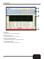
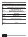
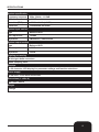
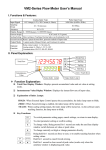
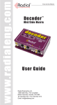
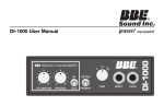
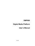
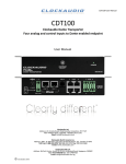
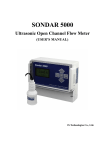
USER MANUAL
P R O F E S S I O N A L
D I G I T A L
P R O C E S S O R
SCS 224 DIGITAL SPEAKER PROCESSOR
Order code: PROC04
w w w . p r o l i g h t . c o . u k
ENGLISH
WARNING
FOR YOUR OWN SAFETY, PLEASE READ THIS USER MANUAL CAREFULLY
BEFORE YOUR INITIAL START-UP!
CAUTION!
Keep this equipment away from rain,
moisture and liquids.
SAFETY INSTRUCTIONS
Every person involved with the installation, operation & maintenance of this
equipment should:
-
Be competent
-
Follow the instructions of this manual
CAUTION! TAKE CARE USING THIS EQUIPMENT!
HIGH VOLTAGE-RISK OF ELECTRIC SHOCK!!
Before your initial start-up, please make sure that there is no damage caused during
transportation. Should there be any, consult your dealer and do not use the
equipment.
To maintain the equipment in good working condition and to ensure safe operation, it is necessary
for the user to follow the safety instructions and warning notes written in this manual.
Please note that damages caused by user modifications to this equipment are not
subject to warranty.
2
IMPORTANT:
The manufacturer will not accept liability for any resulting damages caused
by the non-observance of this manual or any unauthorised modification to the
equipment.
• Never let the power-cable come into contact with other cables. Handle the power-cable
and all mains voltage connections with particular caution!
• Never remove warning or informative labels from the equipment.
• Do not open the equipment and do not modify the equipment.
• Do not switch the equipment on and off in short intervals, as this will reduce the
system’s life.
• Only use the equipment indoors.
• Do not expose to flammable sources, liquids or gases.
• Do not carry the unit with only one handle. Always carry using both handles.
• Always disconnect the power from the mains when equipment is not in use or before
cleaning! Only handle the power-cable by the plug. Never pull out the plug by pulling the
power-cable.
• Make sure that the available voltage is between 220v/240v.
• Make sure that the power-cable is never crimped or damaged. Check the equipment and
the power-cable periodically.
• If the equipment is dropped or damaged, disconnect the mains power supply immediately.
Have a qualified engineer inspect the equipment before operating again.
• If the equipment has been exposed to drastic temperature fluctuation (e.g. after
transportation), do not switch it on immediately. The arising condensation might damage
the equipment. Leave the equipment switched off until it has reached room temperature.
• If your product fails to function correctly, discontinue use immediately. Pack the unit
securely (preferably in the original packing material), and return it to your Prolight dealer
for service.
• Only use fuses of same type and rating.
• Repairs, servicing and power connection must only be carried out by a qualified
technician. THIS UNIT CONTAINS NO USER SERVICEABLE PARTS.
• WARRANTY; One year from date of purchase.
OPERATING DETERMINATIONS
If this equipment is operated in any other way, than those described in this manual,
the product may suffer damage and the warranty becomes void.
Incorrect operation may lead to danger e.g.: short-circuit, burns, electric shocks,
lamp failure etc.
Do not endanger your own safety and the safety of others!
Incorrect installation or use can cause serious damage to people and property.
Note: This unit is only compatible with Windows XP.
3
Functions
• 2 balanced inputs and 4 balanced outputs for 2 x 4 processor.
• 24-bit and 48kHz sampling rate, ∑ - ∆ AD/AC convertor, 32-bit DSP chip.
• Input processors; Gain, mute, noise gate, 8 parameter EQ and delay.
• Output processors; Crossover, 5 parameter EQ, gain, mute, compressor/limiter and delay.
• Flexible matrix assignments on every input and output channel.
• Adjustable PEQ frequency, gain and bandwidth with selectable types;
(PEAK, H-SHELVE and L-SHELVE).
• Selectable styles of high/low-cut filters;
Butterworth, Linkwitz-Riley, Bessel; slope choice is from -6dB/0ct - -48dB.0ct.
• Adjustable compressor/limiter threshold, ratio, attached and release times.
• Adjustable threshold, attach/release times of all noise gates.
• Easy parameter copying
• 32 user presets, PC software, USB and RS-232 control, online remote control and 256 units are
linkable through the RS-485.
Front Panel
1) Input level indicators: 5 precision LEDs show the amount of input level on each channel
2) Input Mute button: Mutes the selected input channel.
3) Edit buttons:
“UTIL”: Chooses the systems menu.
“SAVE”: Saves the current setup and acts as a up button.
“RECALL”: Recalls past saved preset settings and acts as a down button.
“EXIT”: To exit each function.
4) LCD display: Shows the status of the current mode.
5) Parameter control: Edits and confirms the parameter presets.
6) Output level indicators: 4 precision LEDs and 1 signal LED shows the current state of
the output level on each channel.
7) Output Mute button: This button mutes the selected output channel.
8) USB connector: To connect to the PC and control equipment.
4
Rear Panel
1) Input power supply: Connects the IEC power cable
2) On/Off switch: Powers the unit on and off.
3) In/Out link sockets: To link further units or to connect to a PC
In: CAT-5 cable - 1-Pin RS-485+, Out: CAT-5 - 2-Pin RS-4854) 3-Pin XLR output sockets (1 -8)
5) 3-Pin XLR input sockets (A-D)
Operation:
To operate the unit please follow the instructions below;
1. On power up, the unit will show the brand, model and the software version.
2. Once it has finished self checking the LCD display will show the brand, model and the
current preset status.
To enter the ID setting for the first time please follow the instructions below.
1. To enter an ID for the first time press the “UTIL” button and choose from 1-254.
If there is more than 16 units to be linked or if there is a long distance between each
link a parallel connection is needed with a 120Ω resister on the end of the RS-485 cable.
2. Now press the “UTIL” button to enter a protection code, the code can either be a word
or a set of numbers.
Please note that the protection code is preset as “LOCK”.
3. Press the “UTIL” button a third time to enter a signal source setting.
Signal source setting include: pink/white noise and sine wave (20kHz-20kHz).
4. Press the “UTIL” button again to enter the copy menu function. You can now choose
between the input and output channels.
5. Now press the “UTIL” button a final time to enter a delay setting; ‘mS’, “m” or “ft”.
5
Operation To recall or save any of the settings please follow the instructions below.
1. To recall one of your saved settings, press the “RECALL” button and choose form one
of the saved settings: “U-00” - “U-30” or simply recall “F00”
2. To save the settings, press the “SAVE” button to enter the preset save option.
You can save the setting into “U-00” - “U-30”.
Note that “F00” can not be saved into.
To enter the edit function on the output channels press and hold the “MUTE” button and follow the
instructions below.
1. After you have pressed the “MUTE” button “input gain” will be displayed on the
LCD screen.
The setting are from -60dB~+12dB.
2. Press the “RECALL” button to edit the PEQ parameter settings; PEQ numbers 1-8 can
be selected:
The scale of “F” is 20Hz - 20kHz, “Q” is 0.4 - 128 and “G” is -12dB - +12dB.
The style of the filter is PEAK: LOW/HIGH - SHELF, bypass On/Off.
3. Press the ”RECALL” button again to edit the “NOISE GATE” settings.
“THRESHOLD” settings are from -90dB - -0dB.
“ATT” start up times range from 1mS - 200mS.
“RE” times range from 1mS - 999mS.
4. Now press the “RECALL” button a final time to edit the “DELAY” parameter settings.
The settings for “ms” are from 0-688mS.
The settings for “m” are from 0-234m.
The settings for “ft” are from 0-769ft.
To enter the edit function on the output channels press and hold the “MUTE” button and follow the
instructions below.
1. After you have pressed the “MUTE” button “output gain” will be displayed on the
LCD screen.
The setting are from -60dB~+12dB.
2. Press the “RECALL” button to edit the PEQ parameter settings; PEQ numbers 1-8 can
be selected:
The scale of “F” is 20Hz - 20kHz, “Q” is 0.4 - 128 and “G” is -12dB - +12dB.
The style of the filter is PEAK: LOW/HIGH - SHELF, bypass On/Off.
3. Now press the “RECALL” button a final time to edit the “DELAY” parameter settings.
The settings for “ms” are from 0-688mS.
The settings for “m” are from 0-234m.
The settings for “ft” are from 0-769ft.
4. Press the “RECALL” button to edit the high/low parameter settings:
“HP” ranges from 20Hz - 20kHz., “LP” ranges from 20Hz - 20kHz.
There are three slanting rates for the high/low pass filter: “BUTTERWORTH”, “BESSEL”
and “LINKWITZ”, the slanting rate is 2 x 4/3 x 6 is -6dB - -48dB, 4 x 8 is -6dB - -24dB.
5. Press the “RECALL” button to edit the matrix settings:
All of the output channels can be selected from single or multiple input signals.
6. Press the “RECALL” button to edit the compressor settings. The settings are as follows:
“THRESHOLD” is -90dB - -0dB.
“A” is 1mS - 200mS, “R” is 1mS - 999mS.
The compress rate is 1:1, 1:1.3, 1:1.5 - LIMIT.
7. Press the “RECALL” button a final time to edit the phase settings:
The phase settings range from 0˚ - 180˚.
(Press the “SAVE” button to switch over to editing; please note that the sequence will be
the opposite way around).
6
PC SETUP
NOTE: This software is only compatible with WINDOWS XP.
The operation instructions, USB drive and PC software are all included on the CD.
1) After you have inserted the software installation disc into your PC, double click on the
“CDM 2. 04.16.exe” file. The image below will be displayed on your screen during this process.
2) Once the driver has been installed, double click on the “PC software” on the CD and click
“NEXT STEP” to continue. This will now carry on until the instruction “finishing setup” appears.
When it has finished installing the software you can then exit.
3) Now connect the unit to the PC using the supplied USB cable. After turning on the unit your PC
will automatically update the hardware. During setting up the hardware, there will be a couple of
pop-up warnings;
“FOUND NEW HARDWARE” and “HARDWARE SETUP SUCCESS AND CAN BE USED”.
7
PC SETUP
4) Click on “MY COMPUTER” and right click on the “PROPERTIES” and choose
“DEVICE MANAGER” in the “HARDWARE” section, as shown in the image below.
5) When the device manager window is open, check the “COM” number in the “USB SERIAL
PORT”, this should be below “COM” (COM and LPT) as shown in the image below.
(If you find that the COM is above COM8, please amend it below 8 on the menu COM set up)
8
PC SETUP
6) Open the software application and click on the “COM SETUP” in the “TOOLS” drop down
window, as shown in the image below.
7) A new small window should now appear on your screen (as shown below). Make sure that the
“COM” number is the same as you have previously done at step 5 of this guide and click OK.
9
PC SETUP
8) Now click the “ONLINE”
tab in the
top bar of the window. An “ID select” window
should now appear (see the image on the
right). Make the ID number the same as the
hardware device and click OK.
Note” All of the device’s ID’s are “1”.
9) The software will now do an auto search for
the connected device. When prompted click
OK.
10) It will now show a “RED” status bar at the
bottom of the window when the software has
connected successfully.
To exit the software, you need to click on the
“ONLINE”
tab first before you
disconnect the USB cable or shut down
the device.
10
PC SOFTWARE
1) Main Menu:
Selects the menu for different operations.
2) Function Panel Area:
Selects the menu for different operations.
3) Parameter Adjustment Area:
General parameter setting for the selected function.
4: Preset Operation Area:
Save, transfer or change the preset name.
11
PC SOFTWARE
PC Software Instruction Drop Down Menus
File
Function
Open
Opens a user’s preset document on the computer (*.prs)
Save
Saves the current software setup to a users preset document (*.prs)
Uploads the users preset data of the current connected
device and saves to the computer. (*.unt)
Upload
Download
Downloads the users preset data saved in the current
device and deletes all of the users preset data. (*.unt)
Factory default
Resumes the initial setting of the connected device and
deletes all of the users preset data.
Exit
Exits the software
View
Status bar
Tool bar
Level display
Shows the online status
Shows the tool bar
Shows the input and output level lights
Tools
COM setup
Test zone
COM port setup
Signal tester
Copy’s data between the input and output channels
Copy
12
SPECIFICATIONS
System specification
Frequency response
20Hz - 20kHz, +/-0.5dB
S/N ratio
>115dBu
Distortion (THD)
<0.01% at 1 kHz (-10dBv)
Cross talk
<100d Below full scale
System input section
Type
Balanced XLR
Max. input level
+20dBu
Impedance
1MΩ/stereo; 500kΩ/mono
System output section
Type
Balanced XLR
Max. output level
+20dBu
Impedance
<500Ω
Lighting processing
24-bit sigma delta converters
48kHz sampling rates
Displays
2 x 20 character LCD display for parameter settings and function selections
Power supply
AC’90 255V - Fuse 250V AC/2A Fast
Dimensions (L x W x H)
480 x 205 x 45mm
Weight
2.88Kgs
13
UNIT CONNECTION AND CENTRE CONTROL OPERATION
The RS-232 data from the computer can be converted to the RS-485 mode through an optional
AD-485A. This will make it easier to control the unit from a long distance.
Several units can be linked for long distance control via the RS-485.
The RS-485 can control the operation of several units at long distance via the central control
system.
Achievable long distance control functions by RS-485;
1) Input channel gain
2) Input channel mute on/off
3) Output channel gain
4) Output channel mute on/off
5) Transfer appointed scene
14