1
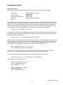
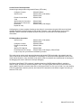
10623 Roselle Street, San Diego, CA 92121 • (858) 550-9559 • FAX (858) 550-7322
[email protected] • www.accesio.com
MODEL PCI-A12-16A
USER MANUAL
FILE: MPCI-A12-16A.A1o
Notice
The information in this document is provided for reference only. ACCES does not assume any liability arising
out of the application or use of the information or products described herein. This document may contain or
reference information and products protected by copyrights or patents and does not convey any license under
the patent rights of ACCES, nor the rights of others.
IBM PC, PC/XT, and PC/AT are registered trademarks of the International Business Machines Corporation.
Printed in USA. Copyright 2004, 2006 by ACCES I/O Products Inc, 10623 Roselle Street, San Diego, CA
92121. All rights reserved.
WARNING!!
ALWAYS CONNECT AND DISCONNECT YOUR FIELD CABLING WITH
THE COMPUTER POWER OFF. ALWAYS TURN COMPUTER POWER OFF
BEFORE INSTALLING A CARD. CONNECTING AND DISCONNECTING
CABLES, OR INSTALLING CARDS INTO A SYSTEM WITH THE
COMPUTER OR FIELD POWER ON MAY CAUSE DAMAGE TO THE I/O
CARD AND WILL VOID ALL WARRANTIES, IMPLIED OR EXPRESSED.
2
Manual PCI-A12-16A
Warranty
Prior to shipment, ACCES equipment is thoroughly inspected and tested to applicable specifications.
However, should equipment failure occur, ACCES assures its customers that prompt service and support will
be available. All equipment originally manufactured by ACCES which is found to be defective will be repaired
or replaced subject to the following considerations.
Terms and Conditions
If a unit is suspected of failure, contact ACCES' Customer Service department. Be prepared to give the unit
model number, serial number, and a description of the failure symptom(s). We may suggest some simple
tests to confirm the failure. We will assign a Return Material Authorization (RMA) number which must appear
on the outer label of the return package. All units/components should be properly packed for handling and
returned with freight prepaid to the ACCES designated Service Center, and will be returned to the
customer's/user's site freight prepaid and invoiced.
Coverage
First Three Years: Returned unit/part will be repaired and/or replaced at ACCES option with no charge for
labor or parts not excluded by warranty. Warranty commences with equipment shipment.
Following Years: Throughout your equipment's lifetime, ACCES stands ready to provide on-site or in-plant
service at reasonable rates similar to those of other manufacturers in the industry.
Equipment Not Manufactured by ACCES
Equipment provided but not manufactured by ACCES is warranted and will be repaired according to the terms
and conditions of the respective equipment manufacturer's warranty.
General
Under this Warranty, liability of ACCES is limited to replacing, repairing or issuing credit (at ACCES
discretion) for any products which are proved to be defective during the warranty period. In no case is ACCES
liable for consequential or special damage arriving from use or misuse of our product. The customer is
responsible for all charges caused by modifications or additions to ACCES equipment not approved in writing
by ACCES or, if in ACCES opinion the equipment has been subjected to abnormal use. "Abnormal use" for
purposes of this warranty is defined as any use to which the equipment is exposed other than that use
specified or intended as evidenced by purchase or sales representation. Other than the above, no other
warranty, expressed or implied, shall apply to any and all such equipment furnished or sold by ACCES.
3
Manual PCI-A12-16A
Table of Contents
Chapter 1: Introduction .................................................................................................................................... 5
Description .................................................................................................................................................... 5
Input System Expansion .............................................................................................................................. 5
Discrete Digital I/O........................................................................................................................................ 6
Counter/Timer ............................................................................................................................................... 6
Analog Outputs ............................................................................................................................................. 6
Interrupts ....................................................................................................................................................... 6
Transferring Data into the Computer.......................................................................................................... 6
Reference Voltage and Power Required .................................................................................................... 6
Specifications................................................................................................................................................ 7
Figure 1-1: Block Diagram......................................................................................................................... 9
Chapter 2: Installation .................................................................................................................................... 10
Configure Card Options via Jumper Selection........................................................................................ 10
CD Software Installation ............................................................................................................................ 10
WINDOWS ............................................................................................................................................... 10
LINUX....................................................................................................................................................... 10
Hardware Installation ................................................................................................................................. 11
Chapter 3: Option Selection........................................................................................................................... 12
Figure 3-1: Option Selection Map............................................................................................................ 13
Chapter 4: Address Selection........................................................................................................................ 14
Chapter 5: Programming ................................................................................................................................ 15
Table 5-1: Register addresses on the card (hex) .................................................................................... 15
Register Descriptions................................................................................................................................. 16
Software Tristate Mode .............................................................................................................................. 20
Programming Guide ................................................................................................................................... 21
Chapter 6: Programmable Interval Timer ..................................................................................................... 24
Operational Modes ..................................................................................................................................... 24
Programming............................................................................................................................................... 26
Programming Examples............................................................................................................................. 29
Chapter 7: Calibration..................................................................................................................................... 31
Chapter 8: Connector Pin Assignments ....................................................................................................... 32
Table 8-1: Analog Connector Pin Assignments....................................................................................... 32
Table 8-2: Digital Connector Pin Assignments ........................................................................................ 33
Customer Comments...................................................................................................................................... 34
4
Manual PCI-A12-16A
Chapter 1: Introduction
The card is a multifunction high-speed analog-to-digital converter card for use in 5-volt and 3.3-volt PCI bus
computer slots. With this card installed the computer can be used as a precision data acquisition and control
system or as a signal analysis instrument.
Description
The card accepts up to eight differential or 16 single-ended analog input channels. Inputs are protected
against over-voltage conditions up to +35 volts and typically survive static discharges beyond 4000 volts. The
channel input configuration is software selectable. When using the card in differential mode the common
mode rejection ratio is a minimum 80dB at 45KHz and the common mode voltage rejection capability is +11V.
The input signals are amplified by an onboard instrumentation amplifier to provide voltage ranges of 10, 5,
1.25-6.25, and 1.25-3.75 volts unipolar and ±10, ±5, ±2.5 and ±1.25 volts bipolar. In addition, you can read 420 mA current inputs by manually installing jumpers to utilize onboard resistors. In this case, the current input
is converted to an analog voltage range of 1.25-6.25V with full 12-bit resolution and there can be up to eight
inputs. Each channel must be dedicated to either voltage or current.
This card contains an industry standard 12-bit successive-approximation analog-to-digital converter (A/D) with
a sample and hold amplifier input. Under ideal conditions throughput of over 100,000 conversions per second
is possible.
This card has a 4k samples FIFO data buffer and a 4k words point list buffer. These buffers give capability for
full-speed counter-driven background data-acquisition with no computer interaction until the data FIFO needs
draining. This allows 100kHz data to be taken with little processor overhead.
A/D conversions may be initiated in any of three ways: (a) software command, (b) an on-board programmable
timer, or (c) direct external trigger. In turn, data may be transferred to the computer by any of three software
selectable methods: (a) polling for end-of-conversion (EOC), (b) polling for a half-full FIFO, or (c) a half-FIFO
interrupt.
Input System Expansion
This card can be used with up to 16 external AIM-16P analog input expansion cards. Each AIM-16P card
provides capability for 16 differential inputs and thus can be used to provide a maximum of 256 analog inputs
per combination of analog input expansion cards and a single A12-16A. The initial AIM-16Ps are connected to
the card by a special cable adapter and ribbon cable. Additional AIM-16P units are connected by daisychaining with ribbon cables. In the normal system configuration each AIM-16P is connected to a single-ended
input of this card. However, if interconnection cable noise becomes problematic or if long cables are required,
then the AIM-16P cards can be connected to the differential inputs of the card. Using the differential
connection allows better monitoring of remote locations because noise will be reduced by the common mode
noise rejection capability of the card. (Note: In this configuration, the maximum number of inputs that can be
handled is 128.)
Note: If the VRef from the card is to be used to power a bridge or other apparatus connected to the AIM-16,
then pin 28 on J1 of the the card must be grounded. Consult the factory to obtain a specially modified card
that implements this option.
The control register at base address+3 provides channel and gain control bits for use with submultiplexers
like the AIM-16. SEL3-SEL0 are typically used for channel, and G2-G0 are used for gain. If no submulitplexer
is being used, it is a good idea to use SEL3-SEL0 as ID tags. These values will comprise the top four bits of
the data returned from the A/D converter.
5
Manual PCI-A12-16A
Discrete Digital I/O
24 bits of TTL/CMOS compatible digital I/O capability are provided. The 24 bits of digital output are controlled
by an 8255-style programmable peripheral interface chip. These 24 bits are arranged into three 8-bit ports,
which can be independently programmed to be inputs or outputs. One of the ports (Port C) may be split into
two 4-bit ports.
These 24 bits are available on a separate 50 Pin header and are buffered. A fused +5 VDC is also available
on Pin 49 of that header.
Counter/Timer
This card contains a type 8254 counter/timer that has three 16-bit programmable down counters.
Counter/Timer 0 is enabled by a pin on the connector (CTR0) and uses an external clock of up to 10 MHz as
selected by user software. Counter/Timers 1 and 2 are concatenated to form a 32-bit counter and receive 1
MHz clock inputs from an on-board crystal-controlled oscillator.
The counter/timers can be set up for event counting, frequency or period measurements, and pulse or wave
form generation. Also, Counter/Timers 1 and 2 can be programmed to initiate A/D conversions. A driver with
source code is provided to facilitate use of the counter/timer chip in data acquisition applications.
Analog Outputs
Two digital-to-analog converters are provided. They are controlled by an AD7237 dual DAC. They are
independently configurable by means of on-board switches. Each may be configured to unipolar or bipolar
outputs and may have full-scale ranges of 2.5, 5, or 10 volts.
Interrupts
This card has interrupt capability within the PCI bus. The interrupt for the card can be software enabled and
can be initiated by various FIFO status conditions.
Transferring Data into the Computer
This card has been designed to provide high data throughput using the PCI bus. Direct I/O transfers provide
the easiest means of transferring the data to memory. This type of transfer allows data to be sent at rates of
over 100,000 samples per second.
Also, program transfers are subject to disruption by other interrupt processes in the computer. Use of real
time triggering of the A/D assures synchronized sampling that is unaffected by other computer operations.
That capability is essential in applications such as signal analysis, fast Fourier transform, and vibration and
transient analysis where high data rates must be sustained for short intervals of time. The FIFO on the card
allows it to acquire data from a list of channels using a point-list FIFO and to store the data in the onboard
data FIFO, eliminating most timing concerns.
Reference Voltage and Power Required
A ±10V (±0.25) reference voltage is available from the A/D reference source for external use. This reference
output can source up to 200 mA of current. The card requires only +5VDC and ±12VDC from the computer
power supply.
6
Manual PCI-A12-16A
Specifications
A/D Specification
•
Type:
Successive approximation.
•
Resolution:
12 binary bits.
•
Conversion Time:
8 µsec max., 5.7 µsec typical.
•
Integral Linearity Error:
±0.45 LSB maximum.
•
Differential Non-Linearity:
No missing codes.
•
Monotonicity:
Guaranteed over operating temperature range.
•
Linearity:
±1 bit.
•
Zero Drift:
±10 ppm/°C maximum.
•
Gain Drift:
±45 ppm/°C maximum.
•
Trigger Source:
Software selectable, external trigger, programmable timer, or
program command.
Sample and Hold Amplifier
•
Acquisition Time:
1 microsecond to 0.01% typical for full scale step function
input.
•
Aperture Uncertainty:
0.3 nanosecond typical.
Reference Voltage Output
•
Voltage:
+10VDC ±0.25VDC.
•
Temp. Coefficient:
±30 ppm/°C.
•
Load Drive:
200mA maximum.
•
Logic high:
2.0 to 5.0 VDC at 20 uA maximum at 2.7V.
•
Logic low:
-0.5 to +0.8 VDC at -0.4mA maximum.
•
Drivers are 74ABT245s.
•
Logic High:
2.0 VDC min., -32mA.
•
Logic Low:
0.5 VDC max., 64mA.
•
Power Output:
+5 VDC from computer bus (onboard resettable 0.5A fuse).
Digital I/O
Inputs
Output
7
Manual PCI-A12-16A
D/A Specification
•
Type:
AD7237, Dual 12-Bit D/A’s with 12 bit resolution.
•
Output ranges:
0-2.5, 0-5, 0-10, ±2.5, ±5 and ±10 volts are selectable.
•
Load Drive:
±15mA maximum per output.
Programmable Timer
•
Type:
82C54-2 programmable interval timer.
•
Counters:
Three 16-bit down counters, two permanently concatenated
with 1MHz clock as programmable timer.
•
Output Drive:
2.2mA at 0.45V (5 LSTTL loads).
•
Input Gate:
TTL/DTL/CMOS compatible.
•
Clock Frequency:
DC to 10MHz.
•
Active Count Edge:
Negative edge.
•
Min Clock Pulse Width:
30nS high/50nS low.
•
Timer Range:
2.5 MHz to <1 pulse/hr.
•
Operating Temp:
0 °C. to 50 °C.
•
Storage Temp:
-20 °C. to +70 °C.
•
Humidity:
0 to 90% RH, non-condensing.
•
Power Required:
+5VDC:
+12VDC:
-12VDC:
Environmental
8
600 mA typical.
650 mA typical.
650 mA typical.
Manual PCI-A12-16A
UNI
BIP
UNIPOLAR/
BIPOLAR
SELECT
VREF
16 S.E./
8 DIFF'L
SWITCH
SAMPLE/
HOLD
CH0 HI
CH0 LO
16 S.E.
OR
8 DIFF'L
ANALOG
INPUTS
MUX
1
2
4
8
12 BIT A/D CONVERTER
A/D & MUX
GAIN
SELECT
DATA REGISTER
STATUS
REGISTER
CH15
MUX INCREMENT
& CONTROL LOGIC
GN0
GN1
GN2
SEL0
SEL1
SEL2
SEL3
7 BIT
OUTPUT
REGISTER
(SUBMUX
CONTROL)
DATA
INTERNAL DATA BUS
BUFFERS
TRIGGER
SELECT
LOGIC
A/D TRIG
DIO0
1MHz
XTAL
24 BITS
8255
DIGITAL
INPUT /
OUTPUT
INTERFACE
TTL
DIGITAL
I/O
DIO23
I
G
I
G
16
BIT
CTR
0
16
BIT
CTR
1
O
O
I
DAC 1
P
C
I
B
U
S
ADDRESS
DECODE
&
SELECT
G
16
BIT
CTR
2
CONTROL
REGISTER
O
DAC 0
DAC 0
AND
DAC 1
I
B
M
INTERRUPT
CTR0
CLOCK
IN
CTR2
OUT
CONTROL
Figure 1-1: Block Diagram
9
Manual PCI-A12-16A
Chapter 2: Installation
A printed Quick-Start Guide (QSG) is packed with the card for your convenience. If you’ve already performed
the steps from the QSG, you may find this chapter to be redundant and may skip forward to begin developing
your application.
The software provided with this card is on CD and must be installed onto your hard disk prior to use. To do
this, perform the following steps as appropriate for your operating system.
Configure Card Options via Jumper Selection
Before installing the card into your computer, carefully read Chapter 3: Option Selection of this manual, then
configure the card according to your requirements. Our Windows based setup program can be used in
conjunction with Chapter 3 to assist in configuring jumpers on the card, as well as provide additional
descriptions for usage of the various card options.
CD Software Installation
The following instructions assume the CD-ROM drive is drive “D”. Please substitute the appropriate drive
letter for your system as necessary.
WINDOWS
1.
Place the CD into your CD-ROM drive.
2.
The system should automatically run the install program. If the install program does not run promptly,
click START | RUN and type BGLQR?JJ, click OK or press -.
3.
Follow the on-screen prompts to install the software for this board.
LINUX
1.
Please refer to linux.htm on the CD-ROM for information on installing under linux.
Caution! * ESD A single static discharge can damage your card and cause premature failure!
Please follow all reasonable precautions to prevent a static discharge
such as grounding yourself by touching any grounded surface prior to
touching the card.
10
Manual PCI-A12-16A
Hardware Installation
1.
2.
3.
4.
5.
6.
7.
8.
9.
10.
Make sure to set switches and jumpers from either the Option Selection section of this manual or
from the suggestions of SETUP.EXE.
Do not install card into the computer until the software has been fully installed.
Turn OFF computer power AND unplug AC power from the system.
Remove the computer cover.
Carefully install the card in an available 5V or 3.3V PCI expansion slot (you may need to remove a
backplate first).
Inspect for proper fit of the card and tighten screws. Make sure that the card mounting bracket is
properly screwed into place and that there is a positive chassis ground.
Install an I/O cable onto the card’s bracket mounted connector.
Replace the computer cover and turn ON the computer which should auto-detect the card (depending
on the operating system) and automatically finish installing the drivers.
Run PCIfind.exe to complete installing the card into the registry (for Windows only) and to determine
the assigned resources.
Run one of the provided sample programs that was copied to the newly created card directory (from
the CD) to test and validate your installation.
The base address assigned by BIOS or the operating system can change each time new hardware is installed
into or removed from the computer. Please recheck PCIFind or Device Manager if the hardware configuration
is changed. Software you write can automatically determine the base address of the card using a variety of
methods depending on the operating system. In DOS, the PCI\SOURCE directory shows the BIOS calls used
to determine the address and IRQ assigned to installed PCI devices. In Windows, the Windows sample
programs demonstrate querying the registry entries (created by PCIFind and NTIOPCI.SYS during boot-up) to
determine this same information.
11
Manual PCI-A12-16A
Chapter 3: Option Selection
To operate the card in the current mode, install a jumper in the positions shown at CH0 through CH7 for each
channel, 0 to 7 you will be using as a current input. Only differential operation is supported when using current
mode inputs. For best results using 4-20mA inputs, the 1.25-6.25 volt range is recommended.
The Buffer Enable / Buffer Tristate (BEN/BTR) jumper enables or disables software tristating of the digital I/O
bits. Normally, this jumper will be installed in the BEN position. In order to use the software tristate feature,
install this jumper in the BTR position; this will change the behavior of the DIO bits as described in the
Programming chapter.
The range of each DAC is set by a block of switches on the board. The ranges correspond to switch settings
as follows:
Switch
Range
3
2
1
ON
OFF OFF
0-2.5V
OFF OFF OFF
0-5V
OFF ON
0-10V
ON
OFF
OFF ON
±2.5V
OFF OFF ON
±5V
OFF ON
±10V
ON
12
Manual PCI-A12-16A
CH0
CH7
S E LE C T
IN P U T
CHANNEL
AS
4-20mA
RP1
RP2
RP3
FA C TORY
USE
ON LY
DAC0 DAC1
RP5
RP6
BTR BEN
RP7
RP8
Pin 1
Figure 3-1: Option Selection Map
13
Manual PCI-A12-16A
Chapter 4: Address Selection
This card uses I/O addresses offset from the base address assigned by the PCI bus. The address spaces are
defined in the programming section of this manual.
PCI architecture is Plug-and-Play. This means that the BIOS or Operating System determines the resources
assigned to PCI cards rather than the user selecting those resources with switches or jumpers. As a result,
you cannot set or change the card's base address or IRQ level. You can only determine what the system has
assigned.
To determine the base address that has been assigned, run the PCIFind utility program. This utility will
display a list of all the cards detected on the PCI bus, the addresses assigned to each function on each of the
cards, and the respective IRQs.
Alternatively, Windows systems can be queried to determine which resources were assigned. In these
operating systems, you can use either PCIFind, or the Device Manager utility from the System Properties
Applet of the control panel. The card is installed in the Data Acquisition class of the Device Manager list.
Selecting the card, clicking Properties, and then selecting the Resources Tab will display a list of the
resources allocated to the card.
The PCI bus supports 64K of I/O address space, so your card's addresses may be located anywhere in the
0000h to FFFFh range.
PCIFind uses the Vendor ID and Device ID to search for your card, then reads the base address and IRQ. If
you want to determine the base address and IRQ without using PCIFind, use the following information:
The Vendor ID for this card is 494F. (ASCII for "IO")
The Device ID for this card is ECAAh.
An example of how to locate PCI card resources is provided with in the PCI\SOURCE directory, under your
installation directory. This code runs in DOS, and uses the PCI defined interrupt BIOS calls to query the PCI
bus for card specific information. You will need the Device ID and Vendor ID listed above to use this code.
14
Manual PCI-A12-16A
Chapter 5: Programming
Offset Write Function
Read Function
0
Start Conversion
A/D Conversion Data, 8 Least Significant Bits (LSB)
1
unused
A/D Conversion Data, 4 Most Significant Bits (MSB)
2
A/D Control (Channel and Range) A/D Control Readback
3
Digital Output / Sub-Mux Control
Digital Output Readback
4
Option Control
Option Status, Clears Interrupt
5
unused
unused
6
unused
unused
7
unused
unused
8
8254 Counter / Timer 0
8254 Counter / Timer 0
9
8254 Counter / Timer 1
8254 Counter / Timer 1
A
8254 Counter / Timer 2
8254 Counter / Timer 2
B
8254 Counter / Timer Control
8254 Counter / Timer Status
C
DAC 0 8 LSB
unused
D
DAC 0 4 MSB
unused
E
DAC 1 8 LSB
unused
F
DAC 1 4 MSB
unused
10
8255 Port A Output
8255 Port A Input / Readback
11
8255 Port B Output
8255 Port B Input / Readback
12
8255 Port C Output
8255 Port C Input / Readback
13
8255 Control
unused
14
Tristate Enable / Disable
unused
Table 5-1: Register addresses on the card (hex)
15
Manual PCI-A12-16A
Register Descriptions
Offset 0 Write
Start Conversion
This address is written to if you wish to start a conversion programmatically. Any value written to this address
will cause the A/D to perform a conversion on the currently selected channel at the currently selected range.
Use the A/D Control register at Offset 2 to select the channel and range. Conversions may also be started via
an External Start Conversion signal (pin 4, see Offset 4) or via Counters (see Offset 4).
Offset 1 Write
Unused
This address is unused, writes are ignored.
Offset 0 Read
A/D Data (Low byte)
Offset 1 Read
A/D Data (High nybble + SEL readback)
These addresses allow you to read the data stored in the data FIFO. The data is read oldest to newest. The
values of SEL3-0 are placed in the four most significant bits of Offset 1 and may be used as a data tag.
Since the data is contained in both of these registers, it is a good practice to read Offset 0 and Offset 1 with a
single word read command to assure that the two data registers stay properly synchronized.
Data is presented in two's complement form. The following shows the bit positions of the data returned:
Read as 16-bit integer from Offset 0
Read as byte from Offset 1
sel3
sel2
sel1
sel0
Read as byte from Offset 0
DB
DA
D9
D8
D7
D6
D5
D4
D3
D2
D1
D0
Read a single 16-bit integer and mask off the high-order 4 bits to obtain a value. See the programming guide
at the end of this chapter for more information.
Sel3 through Sel0 are a readback of the state of the Sel3 through Sel0 bits associated with the point in the
point list FIFO that started the conversion. See Offset 2&3 for an explanation of the Sel bits.
Offset 2&3 Write
A/D Control
Setup Point List
Offset 2&3 Read
A/D Control
Readback
This address (base+2) should be written to using a 16-bit WORD command (out dx,ax). Doing so loads the
point-list FIFO. Repeated writes to this address are used to load an entire point-list into the FIFO for later use.
The format of the WORD is described below. After loading up to 4096 WORDS, you must read a WORD from
this address before starting conversions. Refer to the programming guide at the end of this chapter for more
information on using this register.
Note: it is very useful to use SEL3-SEL0 as markers, as long as external muxes are not being used, to track
which channel data is from. When no external mux is being used, writing the same value to SEL3-SEL0 as
MA3-MA0 causes the data FIFO to appear to hold the channel number (MA3-0), which enables easier
tracking of data and channel number.
The following diagrams define bit functions in the point list:
bit 7
bit 6
bit 5
bit 4
bit 3
bit 2
bit 1
bit 0
MA3
MA2
MA1
MA0
DIFF
R2
R1
R0
bit 15
bit 14
bit 13
bit 12
bit 11
bit 10
bit 9
bit 8
SEL3
SEL2
SEL1
SEL0
(unused)
G2
G1
G0
16
Manual PCI-A12-16A
MA3, MA2, MA1, MA0
These 4 bits form a binary number from 0 to 15. This is the channel number on the A/D board you wish to
setup for conversion. MA3 should be cleared to zero if using Differential mode.
DIFF
This is a control bit for Single-Ended or Differential mode. In Single-Ended mode, the card has 16 channels,
each converted in reference to analog ground. In Differential mode, the card has only 8 channels, and the
conversion returns the voltage difference from the high to the low channel. When the bit is cleared (0), SingleEnded mode is active; a set bit (1) indicates Differential mode.
R2, R1, R0
These bits select the range at which to convert the data. The following table lists the ranges and the bit
combinations for each range.
R2
R1
R0
Range Code
Range
0
0
0
0
bipolar 10 volts, 20 volt span
-10 to +10V
0
0
1
1
bipolar 5 volts, 10 volt span
-5 to +5V
0
1
0
2
bipolar 2.5 volts, 5 volt span
-2.5 to +2.5V
0
1
1
3
bipolar 1.25 volts, 2.5 volt span -1.25 to +1.25V
1
0
0
4
unipolar 10 volts, 10 volt span
0 to 10V
1
0
1
5
unipolar 5 volts, 5 volt span
0 to 5V
1
1
0
6
unipolar 1.25 to 3.75 volts, 2.5 volt span
1
1
1
7
unipolar 1.25 to 6.25 volts*, 5 volt span
*The 1.25-6.25 volt range is designed for use with the Current Mode jumper on each channel. Selecting this
range for those channels that have been placed in current mode results in a 4-20mA range, with full 12-bit
precision.
SEL3, SEL2, SEL1, SEL0, G2, G1, G0
These bits are digital outputs generally used to control channel and gain/range on attached sub-multiplexers
(sub-muxes), such as the AIM-16 or LVDT-8. On our sub-muxes, the SEL bits determine the channel, and the
G bits determine the gain; however, the exact purpose of these bits depends on the sub-mux type used.
Please refer to your sub-mux manual for more information.
The SEL3-0 bits will be returned as the top four bits when the data from the A/D converter is read to the
computer. They may be used to tag the data, if they are not being used for other purposes.
Software may be simplified with a 16-bit “word” write to Base+2, encompassing Base+3 also. That “write”
would look like this:
Base+3
Base+2
bit 7
bit 6
bit 5
bit 4
bit 3
bit 2
bit 1
bit 0
bit 7
bit 6
bit 5
bit 4
bit 3
bit 2
bit 1
bit 0
SEL3
SEL2
SEL1
SEL0
X
G2
G1
G0
MA3
MA2
MA1
MA0
DIFF
R2
R1
R0
17
Manual PCI-A12-16A
Offset 4 Write
Option Control
This register is used to control various features on the card.
bit 7
bit 6
XSCE
CCF
bit 5
bit 4
bit 3
Bit 2
bit 1
bit 0
CF
EIFH
EIFE
CTR
XSCE is External Start Conversion Enable. Setting this bit allows pin 4 on the connector to start conversions.
CCF and CF are Clear Channel FIFO and Clear FIFO (data) respectively. Any time a 1 is written to these bits,
the selected FIFO is reset, effectively clearing its contents.
EIFH set to 1 enables interrupts to occur when the data FIFO becomes Half Full. This is the interrupt most
often used in background-task-based data acquisition.
EIFE set to 1 enables interrupts on FIFO Error. That is, anytime the FIFO is read from when it is already
empty, or when data is lost because the FIFO is full when an A/D conversion finishes.
CTR set to 1 causes start conversions to occur each time counter 2 (used in Mode 2) counts down to zero.
The other bits in this register must be cleared to zero for compatibility with future options.
Offset 4 Read
Status, Clear Interrupt
This register is read to determine the status of various features on the card, primarily the state of the point-list
and data FIFOs, or to determine if a conversion has finished.
bit 7
bit 6 bit 5
bit 4 bit 3
bit 2
bit 1 bit 0
BUSY
CFF CFH
CF0 FF
FH
F0
EXT
The BUSY bit indicates the conversion is in process. A zero means the A/D is busy, a one means a
conversion is not in progress. This bit is one of the most important when not using interrupt modes. By
reading this bit you can determine when the A/D conversion has finished and know when to take the data.
CFF, CFH, CF0, FF, FH, and F0 indicate when LOW that the respective status is true. (C)FF is FIFO Full,
(C)FH is FIFO Half Full, and (C)F0 means FIFO Empty.
The EXT bit works like a digital input bit. It shows the current state of the External Start A/D pin on the
connector (pin 4). A/D conversions can be started by pulling this pin high if XSCE is set to one in Offset 4.
Offset 8, 9, A, and B 8254 Counter / Timer
Refer to the 8254 section for information on programming this device.
Offset C & D
DAC 0
These registers are customarily written together in a single word write instruction. The value written is
immediately output on DAC 0.
Offset E & F
DAC 1
These registers are customarily written together in a single word write instruction. The value written is
immediately output on DAC 1.
18
Manual PCI-A12-16A
Offset 10, 11, and 12 8255 Digital I/O Ports
These registers are the ports of the 8255; offset 10 is port A, offset 11 is port B, and offset 12 is port C. Each
port is 8 bits, for a total of 24 bits. Each port’s direction can configured independently via the control register
at offset 13. All ports power up as input ports. Each bit has a weak pull-up, so that with no signal applied, all
inputs read high.
Writing to an output port will update the data on that port. Reading from an output port will read back the
output data. Reading from an input port will read the current data on that port. Writing to an input port is
ignored.
Port C can be treated as two 4-bit ports, C Hi (bits 4-7) and C Lo (bits 0-3), instead of a single 8-bit port.
Often, one is configured as an input port and the other as an output port, to provide a few control signals in
each direction. Since writes to inputs are ignored, one can be written to without affecting the inputs of the
other.
Offset 13
8255 Control
This register is normally used to control the direction of the 8255 digital I/O ports. Port modes can also be set
here, however the card is only designed for mode 0; contact the factory for a custom solution if modes 1 or 2
are desired. Bit assignments in this control byte are as follows:
Bit
Assignment
Function
D0
Port C Lo (C0-C3)
1 = Input, 0 = Output
D1
Port B
1 = Input, 0 = Output
D2
Mode Selection (B & C Lo)
Use 0
D3
Port C Hi (C4-C7)
1 = Input, 0 = Output
D4
Port A
1 = Input, 0 = Output
D5
Mode Selection (A & C Hi)
Use 0
D6
Mode Selection (Mode 2)
Use 0
D7
Mode Set Flag
Use 1
Three common control bytes (in hex):
80 - Set all ports to output.
9B - Set all ports to input. This is their power-on configuration.
83 - Set ports A and C Hi to output, set ports B and C Lo to input.
19
Manual PCI-A12-16A
Software Tristate Mode
Normally, whenever a control byte is written, all output bits go low, discarding their previous values if they
were already outputs. (This is for compatibility with the industry-standard 8255 chip.)
For example, if the DIO were configured as follows:
•
Port A:
Output, data C5
•
Port B:
Input
•
Port C Hi:
Output, data 0
•
Port C Lo:
Input
And a control byte of 81 (hex) were written, the DIO would change as follows:
•
Port A:
Output, data 00
•
Port B:
Output, data 00
•
Port C Hi:
Output, data 0
•
Port C Lo:
Input
If one of those high bits in port A were an active-low siren, then it would sound. If port A were then reinitialized by software, the microsecond that takes would still result in a small pulse, which would trigger
latched sensors.
To alleviate this issue, this card has a software tristate mode, enabled by installing the BEN/BTR jumper in
the BTR position. In software tristate mode, whenever a control byte is written, all ports are tristated. Your
software should re-initialize the output ports, then de-tristate them, causing them to all update simultaneously.
Pull-ups on the card cause tristated bits to appear high, so sensors don’t see a low level when a control byte
is written. (However, little drive current is available; this is not quite the same as an actual high output.)
In order to de-tristate the ports, write the same control byte to Base + 14 as you did to Base + 13 before, but
with D7 set low. In the example above, the control byte to de-tristate the ports would be 01. This register can
also be used to tristate the ports without changing their mode, by writing a control byte to Base + 14 with D7
set high.
20
Manual PCI-A12-16A
Programming Guide
A/D Data Acquisition
Taking data from an A/D can seem confusing at first, but it all boils down to a few simple steps.
Set Point List
Start Conversion
Wait for End of Conversion
Read Data
Repeat
Offset 2 Writes (16-bit words)
Offset 2 Read
Offset 0 Write
Offset 4 Read
Offset 0 Read (16-bit integer)
To set the point list, you must build the point from its component parts. It consists of the channel, the range,
and the differential or single-ended control bit. The range is in the low 3 bits, the SE/DIFF bit is next, then the
channel. From the table in the programming section, you can pick the range number for the desired range,
and in most programs the channel number will come from a FOR loop. Assuming the channel number is in
CH, the range is in RNG, and the SE/DIFF bit is in SEDIFF, you can build a control word with:
control = (CH << 4) + (SEDIFF << 3) + RNG;
This seems fairly complex, but it is made easier if you take into account that most programs will acquire data
from a single range and usually at a single SE/DIFF setting. These two values, then, can be hard-coded into
the program, and the code becomes:
control = (CH << 4) + 1; // for Single-ended, + 5 VDC operation
Write two or more of these points to the point list, and that is all there is for polled mode A/D conversions. The
data comes back in counts, and must be converted to engineering units to be useful. The data is returned in
two's complement form, but resides in only 12 bits. To get a true two's complement integer, you must signextend the data. The following line reads the data and converts it to the simplest form:
data = ((int)inport(base + 0) << 4) >> 4; //C or C++
data := (portw[base + 0] shl 4) DIV 16; {Pascal}
The variable "data" now holds a number from -2048 to 2047 for bipolar ranges, 0 to 4095 for unipolar. A
simple Y = mX + b equation (where X is the data) would convert this to engineering units.
In order to tag the data, a shift becomes easier than a multiply when setting the point list:
control = (CH * 0x1010) + 1; // for Single-ended, + 5 VDC operation
And the read then also retrieves the tag:
rawdata = inport(base + 0); //C or C++
chan = (unsigned)rawdata >> 12;
data = (rawdata << 4) >> 4;
rawdata := portw[base + 0]; {Pascal}
chan := rawdata shr 12;
data := (rawdata shl 4) DIV 16;
21
Manual PCI-A12-16A
Counter Driven Data Acquisition
Several things change when using timed A/D start (CTR mode).
Configure Counters
Set Point List
Enable Counter Mode
*loop
Wait for Start of Conversion
Wait for End of Conversion
Read Data
Repeat at *loop
Offset 8-B Writes
Offset 2 Write (16-bit words)
Offset 2 Read
Offset 4 Write
Offset 4 Read
Offset 4 Read
Offset 0 Read (16-bit integer)
Configuring the counters consists of setting up the timing for conversions using the 8254 control and load
registers described in the 8254 section of this manual. Counters 1 and 2 should both be set for mode 2
operation, and the combined countdown duration of these two counters will be the delay between
conversions.
FIFO Based Data Acquisition
Set Point List
Offset 2 Write (16-bit words)
Offset 2 Read
Offset 8-B Writes
Offset 4 Write
Configure Counters
Enable Counter Mode
*loop
Wait for FIFO Half full
Offset 4 Read
Read Data until FIFO empty
Offset 0 Read (16-bit integer), Offset 4 Read
Loop at *loop until you have as much data as you want
This mode can be used to easily test point-list setup and general FIFO functionality, but generally won't be
used in real-world environments. IRQ based FIFO handling is so efficient that most applications will use that
mode instead. However, many similarities exist and this mode is worthwhile as a experimental or learning aid,
as debugging this mode is easier than interrupt debugging.
Set Channel and Range FIFO consists of a predetermined set of WORD writes to Offset 2, setting the
channel, range, and sub-mux channel and gain if used. The upper nybble (SEL3-SEL0) is returned in the
upper nybble of the A/D conversion data, and is useful as a marker if no mux is to be used. If you are allowing
a user to dynamically create the point-list, the Channel FIFO status bits in the Offset 4 register can warn you
when the FIFO is full.
22
Manual PCI-A12-16A
Interrupt-Based or Background Data Acquisition
Interrupt mode adds wrinkles of its own.
Main program:
Install ISR
Initialize interrupts
Configure Counters
Set Point List
Enable Counter & IRQ Mode
Wait until done.
Motherboard resources
Motherboard resources
Offsets 8-B Writes
Offset 2 Write (16-bit words)
Offset 2 Read
Offset 4 Write
Other code can go here.
ISR:
Read Data until FIFO is empty Offset 0 Read (16-bit integers)
(or read ½ of FIFO size)
Clear Interrupt
Offset 4 Read
Send End-Of-Interrupt
Motherboard resources
Using interrupt mode requires an understanding of IRQ programming practices, such as the PIC IRQ Mask
register and the IRQ vector table. Once these are grasped, however, the benefits are well worth the learning
curve. IRQ mode is a great way to perform non-data-gathering tasks while conversions are taking place. The
background task (the ISR) takes data and stores it, while the foreground task can perform other functions
(such as display, calculations, or acquisition from some other device). This mode is so useful that an example
is provided as part of the sample software normally installed with the card.
Be aware that the card will continually interrupt on the enabled IRQ conditions while those conditions are
"true". This can cause the appearance of "locking-up" a system if the IRQ handler does not remove the
condition before exiting. In the case of FIFO based acquisition, this generally means reading enough data
from the data FIFO that it is no longer more than half-full.
23
Manual PCI-A12-16A
Chapter 6: Programmable Interval Timer
The card contains a type 8254 programmable counter/timer which allows you to implement such functions as
a Real-Time Clock, Event Counter, Digital One-Shot, Programmable Rate Generator, Square-Wave
Generator, Binary Rate Multiplier, Complex Wave Generator, and/or a Motor Controller. The 8254 is a flexible
but powerful device that consists of three independent, 16-bit, presettable, down counters. Each counter can
be programmed to any count between 1 or 2 and 65,535 in binary format, depending on the mode chosen.
On the card these three counters are designated Counter #0, Counter #1, and Counter #2. Counter #0 is undedicated, with the gate, output and clock connections fully accessible via the I/O connector. Counter #0 is
enabled by a discrete input and uses either the internal 1MHz clock or an external clock of up to 10MHz.
Counters #1 and #2 are cascaded together to form a 32-bit counter. This dual counter can be enabled (gated)
by program control and is clocked by a 1MHz precision crystal-controlled internal source.
Please note:
The information in this Appendix is for general reference, and may include features or
functions not applicable to this card.
Operational Modes
The 8254 modes of operation are described in the following paragraphs to familiarize you with the versatility
and power of this device. For those interested in more detailed information, a full description of the 8254
programmable interval timer can be found in the Intel (or equivalent manufacturers) data sheets. The
following conventions apply for use in describing operation of the 8254 :
Clock:
Trigger:
Counter Loading:
A positive pulse into the counter's clock input.
A rising edge input to the counter's gate input.
Programming of a binary count into the counter.
Mode 0: Pulse on Terminal Count
After the counter is loaded, the output is set low and will remain low until the counter decrements to zero. The
output then goes high and remains high until a new count is loaded into the counter. A trigger enables the
counter to start decrementing. This mode is commonly used for event counting with Counter #0.
Mode 1: Retriggerable One-shot
The output goes low on the clock pulse following a trigger to begin the one-shot pulse and goes high when
the counter reaches zero. Additional triggers result in reloading the count and starting the cycle over. If a
trigger occurs before the counter decrements to zero, a new count is loaded. Thus, this forms a re-triggerable
one-shot. In mode 1, a low output pulse is provided with a period equal to the counter count-down time.
Mode 2: Rate Generator
This mode provides a divide-by-N capability where N is the count loaded into the counter. When triggered, the
counter output goes low for one clock period after N counts, reloads the initial count, and the cycle starts over.
This mode is periodic, the same sequence is repeated indefinitely until the gate input is brought low. This
mode is used on the card in Counters #1 and #2 to generate periodic A/D start commands. This mode also
works well as an alternative to mode 0 for event counting.
Mode 3: Square Wave Generator
This mode operates periodically like mode 2. The output is high for half of the count and low for the other half.
If the count is even, then the output is a symmetrical square wave. If the count is odd, then the output is high
for (N+1)/2 counts and low for (N-1)/2 counts. Periodic triggering or frequency synthesis are two possible
applications for this mode. Note that in this mode, to achieve the square wave, the counter decrements by two
for the total loaded count, then reloads and decrements by two for the second part of the wave form.
24
Manual PCI-A12-16A
Mode 4: Software Triggered Strobe
This mode sets the output high and, when the count is loaded, the counter begins to count down. When the
counter reaches zero, the output will go low for one input period. The counter must be reloaded to repeat the
cycle. A low gate input will inhibit the counter. This mode can be used to provide a delayed software trigger
for initiating A/D conversions.
Mode 5: Hardware Triggered Strobe
In this mode, the counter will start counting after the rising edge of the trigger input and will go low for one
clock period when the terminal count is reached. The counter is retriggerable. The output will not go low until
the full count after the rising edge of the trigger.
25
Manual PCI-A12-16A
Programming
On the card, the 8254 counters occupy the following addresses:
Base Address + 8:
Base Address + 9:
Base Address + A:
Base Address + B:
Read/Write Counter #0
Read/Write Counter #1
Read/Write Counter #2
Write to Counter Control register
The counters are programmed by writing a control byte into a counter control register at Base Address + B.
The control byte specifies the counter to be programmed, the counter mode, the type of read/write operation,
and the modulus. The control byte format is as follows:
Base + B Write: Counter Control Byte
B7
B6
B5
B4
B3
B2
B1
B0
SC1
SC0
RW1
RW0
M2
M1
M0
BCD
SC0-SC1: These bits select the counter that the control byte is destined for.
SC1
SC0
Function
0
0
Program Counter #0
0
1
Program Counter #1
1
0
Program Counter #2
1
1
Read/Write Cmd.*
* See section on Reading and Loading the Counters.
RW0-RW1: These bits select the read/write mode of the selected counter.
RW1
RW0
Counter Read/Write Function
0
0
Counter Latch Command
0
1
Read/Write LS Byte
1
0
Read/Write MS Byte
1
1
Read/Write LS Byte, then MS Byte
26
Manual PCI-A12-16A
M0-M2: These bits set the operational mode of the selected counter.
Mode
M2
M1
M0
0
0
0
0
1
0
0
1
2
X
1
0
3
X
1
1
4
1
0
0
5
1
0
1
BCD: Set the selected counter to count in binary (B0 = 0) or BCD (B0 = 1).
Reading and Loading the Counters
If you attempt to read the counters on the fly when there is a high input frequency, you will most likely get
erroneous data. This is partly caused by carries rippling through the counter during the read operation. Also,
the low and high bytes are read sequentially rather than simultaneously and, thus, it is possible that carries
will be propagated from the low to the high byte during the read cycle.
To circumvent these problems, you can perform a counter-latch operation in advance of the read cycle. To do
this, load the RW1 and RW2 bits with zeroes. This instantly latches the count of the selected counter(selected
via the SC1 and SC0 bits) in a 16-bit hold register. (An alternative method of latching counter(s) which has an
additional advantage of operating simultaneously on several counters is by use of a readback command to be
discussed later.) A subsequent read operation on the selected counter returns the held value. Latching is the
best way to read a counter on the fly without disturbing the counting process. You can only rely on directly
read counter data if the counting process is suspended while reading, by bringing the gate low, or by halting
the input pulses.
For each counter you must specify in advance the type of read or write operation that you intend to perform.
You have a choice of loading/reading (a) the high byte of the count, or (b) the low byte of the count, or (c) the
low byte followed by the high byte. This last is of the most general use and is selected for each counter by
setting the RW1 and RW0 bits to ones. Of course, subsequent read/load operations must be performed in
pairs in this sequence or the sequencing flip-flop in the 8254 chip will get out of step.
Base + B Read: Counter Control Byte
CNT:
STA:
C0, C1, C2:
B7
B6
B5
B4
B3
B2
B1
B0
1
1
CNT
STA
C2
C1
C0
0
When is 0, latches the counters selected by bits C0-C2.
When is 0, returns the status byte of counters selected by C0-C2.
When high, select a particular counter for readback. C0 selects Counter 0, C1 selects
Counter 1, and C2 selects Counter 2.
You can perform two types of operations with the Counter Control Byte. When CNT=0, the counters selected
by C0 through C2 are latched simultaneously. When STA=0, the counter status byte is read when the counter
27
Manual PCI-A12-16A
I/O location is accessed. The counter status byte provides information about the current output state of the
selected counter and its configuration. The status byte returned if STA=0 is:
B7
B6
B5
B4
B3
B2
B1
B0
OUT
NC
RW1
RW2
M2
M1
M0
BCD
OUT:
NC:
RW1 & RW0:
M2, M1, M0:
BCD:
Current state of counter output pin.
Null count. This indicates when the last count loaded into the counter register has
actually been loaded into the counter itself. The exact time of load depends on the
configuration selected. Until the count is loaded into the counter itself, it cannot be
read.
Read/Write command.
Counter mode.
BCD = 0 is binary mode, otherwise counter is in BCD mode.
If both STA and CNT bits in the counter status byte are set low and the RW1 and RW0 bits have both been
previously set high in the counter control register (thus selecting two-byte reads), then reading a selected
counter address location will yield:
1st Read:
2nd Read:
3rd Read:
Status byte
Low byte of latched data
High byte of latched data
After any latching operation of a counter, the contents of its hold register must be read before any subsequent
latches of that counter will have any effect. If a status latch command is issued before the hold register is
read, then the first read will read the status, not the latched value. In this case, the latched value may be read
after reading the status.
28
Manual PCI-A12-16A
Programming Examples
Generating a Square Wave Output
To program Counters #1 and #2 for a 1 KHz output you need to divide the 1MHz crystal oscillator input by
1,000. To obtain a symmetrical waveform, the divisor loaded into the counter should be an even number. If it
is an odd number, then one half of the waveform would be one input clock pulse period longer than the other.
A convenient divisor to use in counter #1 is 10 and counter #2 is 100 (because 10 x 100 = 1,000).
outportb(BASEADDRESS + B, 0x76);
outportb(BASEADDRESS + B, 0xb6);
outportb(BASEADDRESS + 9,10);
outportb(BASEADDRESS + 9,0);
outportb(BASEADDRESS + A,100);
outportb(BASEADDRESS + A,0);
/* counter #1 to square wave mode */
/* counter #2 to square wave mode */
/* write lower byte, counter #1 */
/* write upper byte, counter #1 */
/* write lower byte, counter #2 */
/* write upper byte, counter #2 */
Using Counter #0 as a Pulse Counter
Since the counters are "down" counters the resulting count is subtracted from the starting value to determine
the number of pulses. This example starts with a value of 65,535:
outportb(BASEADDRESS + B,0x30);
outportb(BASEADDRESS + 8,0xff);
outportb(BASEADDRESS + 8,0xff);
/* counter #0, mode 0 */
/* counter #0 low load byte */
/* counter #0 high load byte */
Measuring Frequency and Period
The two previous sections show how to count pulses and generate output frequencies. It is also possible to
measure frequency by raising the gate input of Counter 0 for a known time interval and counting the number
of clock pulses accumulated for that interval. The gating signal can be derived from Counters #1 and #2
operating in a square wave mode.
Counter #0 can also be used to measure pulse width or half period of a periodic signal. The signal should be
applied to the gate input of Counter #0 and a known frequency (such as the 1MHz crystal controlled oscillator)
applied to the Counter #0 clock input. During the interval when the gate input is low, Counter #0 is loaded with
a full count of 65,535. When the gate input goes high, the counter begins decrementing until the gate input
goes back low at the end of the pulse. The counter is then read and the change in count is a linear function of
the duration of the gate input signal. Longer pulse durations can be measured if Counters #1 and #2 are used
as the input clock source for Counter #0, or by using an external clock source.
Generating Time Delays
There are four methods of using Counter #0 to generate programmable time delays.
Pulse on Terminal Count
After loading, the counter output goes low. Counting is enabled when the gate goes high. The counter output
will remain low until the count reaches zero, at which time the counter output goes high. The output will
remain high until the counter is reloaded by a programmed command. If the gate goes low during countdown,
counting will be disabled as long as the gate input is low.
Programmable One-Shot
The counter need only be loaded once. The time delay is initiated when the gate input goes high. At this point
the counter output goes low. If the gate input goes low, counting continues but a new cycle will be initiated if
the gate input goes high again before the timeout delay has expired; i.e., is re-triggerable. At the end of the
timeout, the counter reaches zero and the counter output goes high. That output will remain high until retriggered by the gate input.
29
Manual PCI-A12-16A
Software Triggered Strobe
This is similar to Pulse-on-Terminal-Count except that, after loading, the output goes high and only goes low
for one clock period upon timeout. Thus, a negative strobe pulse is generated a programmed duration after
the counter is loaded.
Hardware Triggered Strobe
This is similar to Programmable-One-Shot except that when the counter is triggered by the gate going high,
the counter output immediately goes high, then goes low for one clock period at timeout, producing a
negative-going strobe pulse. The timeout is re-triggerable; i.e., a new cycle will commence if the gate goes
high before a current cycle has timed out.
30
Manual PCI-A12-16A
Chapter 7: Calibration
The cards are calibrated through a software routine contained in the setup program. Once the card is setup,
run the calibration sequence as shown in the program and make the calibration adjustments on RP1, RP2,
RP3, RP5, RP6, RP7, and RP8 on the board.
31
Manual PCI-A12-16A
Chapter 8: Connector Pin Assignments
The analog I/O channels are accessible via a male 37-pin D type connector that extends through the back of
the computer case and a DB37S solder cup plug may be used to make connections.
Pin
Name
Function
1
VDD
+12VDC Power from the Computer Bus
2
CLK0
Counter 0 Clock Input
3
G0
LSBit of AIM-16P Gain Select Bits
4
EXT
External Start Conversion Source Pin
5
G1
Bit 1 of AIM-16P Gain Select Bits
6
G2
MSBit of AIM-16P Gain Select Bits
7
SEL0
Multiplexer Channel Selection Bit LSBit
8
SEL1
Multiplexer Channel Selection Bit
9
SEL2
Multiplexer Channel Selection Bit
10
SEL3
Multiplexer Channel Selection MSBit
11
DGround
Digital Ground
12
GATE1
Counter/Timer Gate Pulse
13
OUT2
Counter/Timer 2 Counter Output
14
DAC0
Analog Output 0
15
DAC1
Analog Output 1
16
no connection
17
IN8-
Chl 7 Analog Low Input (Diff’l) Chl 15 Analog High Input (SE)
18
AGround
Low Level Analog Common Ground
19
VREF
+10VDC Reference Voltage
20
VSS
-12VDC
21
IN7-
Chl 6 Analog Low Input (Diff’l) Chl 14 Analog High Input (SE)
22
IN6-
Chl 5 Analog Low Input (Diff’l) Chl 13 Analog High Input (SE)
23
IN5-
Chl 4 Analog Low Input (Diff’l) Chl 12 Analog High Input (SE)
24
IN4-
Chl 3 Analog Low Input (Diff’l) Chl 11 Analog High Input (SE)
25
IN3-
Chl 2 Analog Low Input (Diff’l) Chl 10 Analog High Input (SE)
26
IN2-
Chl 1 Analog Low Input (Diff’l) Chl 9 Analog High Input (SE)
27
IN1-
Chl 0 Analog Low Input (Diff’l) Chl 8 Analog High Input (SE)
28
AGround
Low Level Analog Common Ground
29
+5VDC
+5VDC Power from Computer Bus
30
IN8
Chl 7 Analog High Input
31
IN7
Chl 6 Analog High Input
32
IN6
Chl 5 Analog High Input
33
IN5
Chl 4 Analog High Input
34
IN4
Chl 3 Analog High Input
35
IN3
Chl 2 Analog High Input
36
IN2
Chl 1 Analog High Input
37
IN1
Chl 0 Analog High Input
Table 8-1: Analog Connector Pin Assignments
32
Manual PCI-A12-16A
The digital I/O bits are accessible via a male 50-pin header connector on the face of the card. The header is
accessible to the user by running a cable through an adjacent mounting bracket. Strain relief mounting
bracket also available.
Assignment
Pin
Assignment
Pin
1
2
Port C Hi Bit 6
3
4
Port C Hi Bit 5
5
6
Port C Hi Bit 4
7
8
Port C Lo Bit 3
9
10
Port C Lo Bit 2
11
12
Port C Lo Bit 1
13
14
Port C Lo Bit 0
15
16
Port B Bit 7
17
Port B Bit 6
19
Port B Bit 5
21
Port B Bit 4
23
Port B Bit 3
25
Port B Bit 2
27
Port B Bit 1
29
Port B Bit 0
31
Port A Bit 7
33
Port A Bit 6
35
Port A Bit 5
37
38
Port A Bit 4
39
40
Port A Bit 3
41
42
Port A Bit 2
43
44
Port A Bit 1
45
46
Port A Bit 0
47
48
+5 VDC @ .5A (Fused)
49
50
All Even Numbered Pins Are Ground
Port C Hi Bit 7
18
20
22
24
26
28
30
32
34
36
Table 8-2: Digital Connector Pin Assignments
33
Manual PCI-A12-16A
Customer Comments
If you experience any problems with this manual or just want to give us some feedback, please email us at:
[email protected]. Please detail any errors you find and include your mailing address so that we can
send you any manual updates.
10623 Roselle Street, San Diego CA 92121
Tel. (858)550-9559 FAX (858)550-7322
www.accesio.com
34
Manual PCI-A12-16A