1
User’s Manual of Board Micro Controller “ET-EASY168 STAMP”
ET-EASY168 STAMP
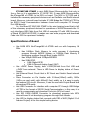
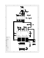
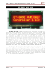
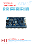
Picture displays structure of Board ET-EASY168 STAMP.
ETT CO., LTD
-1-
WWW.ETT.CO.TH
User’s Manual of Board Micro Controller “ET-EASY168 STAMP”
ET-EASY168 STAMP is mini AVR8 Board Microcontroller that only is
2cm x 5cm or it is equivalent to IC 28 DIP 300. It uses AVR8 Microcontroller
No.ATmega168 of ATMEL to be MCU on board. This MCU is 32 TQFP and it
includes the necessary peripheral devices such as Oscillator and Reset internal
board. Moreover, internal board includes IC USB Bridge No.FT232R of FTDI to
be RS232 Serial Communication between board and computer PC through
Port USB directly.
So, this Board ET-EASY168 STAMP is the mini training board that is full
of the necessary peripheral devices for operations of AVR8 Microcontroller. It
only interfaces USB Cable from Port USB of computer PC with USB Connector
of Board ET-EASY168 STAMP, it makes user can write program and download
Code into MCU to experiment instantly.
Specifications of Board
Use AVR8 MCU No.ATmega168 of ATMEL and run with frequency 16
MHz.
o Has 16KByte Flash Memory to write program if developing
program through AVRISP System; or 14KByte Flash Memory if
developing program through Boot Loader RS232.
o Has 1KByte SRAM and 512Byte EEPROM
o Has 22Bit GPIO
14Bit Digital GPIO
10Bit 8-Channel Analog Input (ADC)
Use +5VDC Power Supply; both +5VDC/500mA from Port USB and
+5VDC from external. There is LED Power to display status of Power
Supply.
Has External Reset Circuit that is RC Reset and Switch Reset internal
board.
Place Connector on Pin Header with 2.54mm(100mil) width, 28Pin
(14Pin per each side) with 600mil(1.5cm) width, so it is easy to apply
and expand I/O circuit. Moreover, it can be used with Project Board and
all-purpose PCB easily.
Has USB Connector to interface with computer PC through USB Bridge
of FTDI in the format of RS232 Serial Communication; in this case, it is
used to communicate and download Code into MCU on board.
Has IDE 10PIN AVRISP Connector to download program into MCU
internal board if not developing program through Boot Loader.
Has LED to display status that connects with PB5 of AVR (Digital-13 of
Arduino Project) to be the simple testing device.
ETT CO., LTD
-2-
WWW.ETT.CO.TH
User’s Manual of Board Micro Controller “ET-EASY168 STAMP”
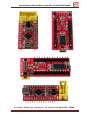
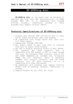
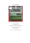
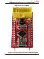
Picture displays features of Board ET-EASY168 STAMP.
ETT CO., LTD
-3-
WWW.ETT.CO.TH
User’s Manual of Board Micro Controller “ET-EASY168 STAMP”
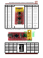
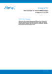
AVR Arduino
PD0 Digital-0
PD1 Digital-1
PD2 Digital-2
PD3 Digital-3
PD4 Digital-4
PD5 Digital-5
PD6 Digital-6
PD7 Digital-7
PB0 Digital-8
PB1 Digital-9
PB2 Digital-10
PB3 Digital-11
PB4 Digital-12
GND
GND
Pin
1
2
3
4
5
6
7
8
9
10
11
12
13
14
ET-EASY168 STAMP
AVRISP
Pin
28
27
26
25
24
23
22
21
20
19
18
17
16
15
Arduino
+5V(+Vin)
+VCC(+5V)
RESET#
Analog-0
Analog-1
Analog-2
Analog-3
Analog-4
Analog-5
Analog-6
Analog-7
+VCC(+5V)
+AREF
Digital-13
AVR
+5V(+Vin)
+VCC(+5V)
RESET(PC6)
PC0/ADC0
PC1/ADC1
PC2/ADC2
PC3/ADC3
PC4/ADC4
PC5/ADC5
ADC6
ADC7
+VCC(+5V)
+AREF
PB5
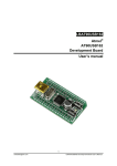
Table shows Pin Arrangement of Board ET-EASY168 STAMP.
AVR
PB3
RES#
PB5
PB4
Arduino
Digital-11
RES#
Digital-13
Digital-12
ETT CO., LTD
Pin
MOSI
NC
RES#
SCK
MISO
AVRISP
-4-
Pin
+VCC
GND
GND
GND
GND
Arduino
+VCC
GND
GND
GND
GND
AVR
+VCC
GND
GND
GND
GND
WWW.ETT.CO.TH
User’s Manual of Board Micro Controller “ET-EASY168 STAMP”
Function of Signal Pins When Using As “Arduino Project”
• +5V(+Vin): This pin receives external +5VDC Power Supply to be
Power Supply of board.
• +VCC(+5V): This pin is Power Supply in the same point of supplying
power to +VCC of MCU. This point receives voltage from 2 sources; Pin
+5V(+Vin) from Pin 28 of Board and Pin +VUSB(+5V) from USB
Connector of board. In this case, there is Diode to protect voltage from
reverse.
• +AREF: This pin receives Signal Reference Voltage (Analog Reference)
for Analog Input Circuit if using external Reference Voltage.
• RESET#: It is RESET Pin of CPU that runs at Logic “0”.
• Digital[0..13]: It is Digital I/O Pin that can be connected with Signal
Logic TTL (5V).
• Analog[0..7]: It is Analog Input Pin that can receive Analog Input in
the range of 0..+5V.
Function of Signal Pins When Using As “AVR Micro Controller”
• +5V(+Vin): This pin receives external +5VDC Power Supply to be
Power Supply of Board.
• +VCC(+5V): This pin is Power Supply in the same point of supplying
to +VCC of MCU. This point receives voltage from 2 sources; Pin
+5V(+Vin) from Pin 28 of Board and Pin +VUSB(+5V) from USB
Connector of board. In this case, there is Diode to protect voltage from
reverse.
• +AREF: This pin receives Signal Reference Voltage (Analog Reference)
for Analog Input Circuit if using external Reference Voltage.
• RESET#: It is RESET Pin of CPU that runs at Logic “0”.
• PB[0..5]: It is Digital I/O Pin that can be connected with signal Logic
TTL (5V).
• PD[0..7]: It is Digital I/O Pin that can be connected with signal Logic
TTL (5V).
• PC[0..5]: It is I/O Pin that can be set both Digital and Analog Input.
• ADC6,ADC7: It is Analog Input Pin that can receive Analog Input in
the range of 0..+5V.
ETT CO., LTD
-5-
WWW.ETT.CO.TH
User’s Manual of Board Micro Controller “ET-EASY168 STAMP”
Program Development of Board ET-EASY168 STAMP
There are 2 types to develop program of Board ET-EASY168 STAMP as
follows;
• AVR Micro Controller: It develops program in the format of normal
AVR Micro Controller. In this case, we can use any language program
that supports AVR No.ATmega168; so, it depends on the skill of user to
choose the desired language for developing program such as BASIC
Language BASCOM-AVR or C Language such as Code Vision and
WinAVR.
• Arduino Project: It uses program and instruction set of C Language
(C++) of “Arduino Project” to write program for program development.
It is the project to develop AVR Microcontroller as Open Source that is
popular nowadays because it reveals all Source Code of program
development. Moreover, there are examples of Development Project for
userd to learn, study and test free without any charge. User can see
more
information
about
this
Arduino
Project
from
http://www.arduino.cc/
************************************************
ETT CO., LTD
-6-
WWW.ETT.CO.TH
User’s Manual of Board Micro Controller ET-EASY168 STAMP
Driver Installation of USB Bridge for Board ET-EASY168 STAMP
Board ET-EASY168 STAMP uses Chip USB Bridge of FTDI to be the
intermediary for connecting and communicating between Computer PC and MCU
ATmega168 of Board ET-EASY168 STAMP in the format of Serial Port (Visual Com
Port). Program Applications that run on computer PC, including Program Arduino will
see Port USB that is connected with Board ET-EASY168 STAMP as a channel of Serial
Port Communication (Com Port) only. If computer PC of user has already been
installed Driver for USB Bridge of FTDI completely, Windows will automatically install
Driver when connecting USB Cable of Board ET-EASY168 STAMP with USB HUB of
Computer PC. On other hand, if Computer PC has never been installed any Driver of
FTDI before, user has to install Driver into Board first as following procedures below;
1. Prepare CD-ROM that contains Driver of FTDI; or if user has already installed
Program of Arduino completely, there is Driver of FTDI internal folder of
Program Arduino in “C:\arduino-0012\drivers\FTDI USB Drivers\”.
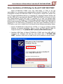
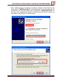
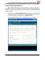
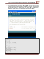
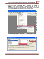
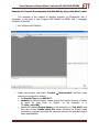
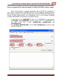
2. Interface USB Cable of Board ET-EASY168 STAMP with Port USB HUB of
Computer PC, Windows will find the new device that is “FT232R USB
UART” and then notify user to install Driver into the device as shown below;
ETT CO., LTD
-7-
WWW.ETT.CO.TH
User’s Manual of Board Micro Controller ET-EASY168 STAMP
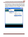
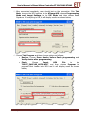
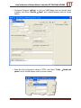
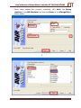
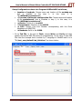
3. Choose “Install from list or specific location (Advance)” and then click
Next; Windows will notify user to specify the location of folder that contains
Driver of FTDI. Choose Browse, choose Drive and Folder that stores File
Driver. If user has already installed program of Arduino completely, choose
“C:\arduino-0012\drivers\FTDI USB Drivers” and then click Next as
shown below;
↓
ETT CO., LTD
-8-
WWW.ETT.CO.TH
User’s Manual of Board Micro Controller ET-EASY168 STAMP
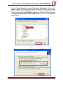
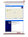
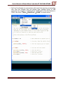
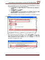
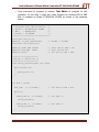
4. In this step, Program Windows will find and install Driver into device, please
wait for a while until the operation is complete and than click Finish as shown
below;
↓
ETT CO., LTD
-9-
WWW.ETT.CO.TH
User’s Manual of Board Micro Controller ET-EASY168 STAMP
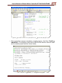
5. After installing Driver of hardware completely, Windows found that the new
device that is “USB Serial Port” is connected and then it will notify user to
install Driver into the new device that is specified as “USB Serial Port”. In
this case, user specifies the location of folder that stores Driver as same as
procedure in step 3 above as shown below;
↓
ETT CO., LTD
-10-
WWW.ETT.CO.TH
User’s Manual of Board Micro Controller ET-EASY168 STAMP
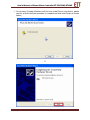
6. In this step, Program Windows will find and install Driver into the device,
please wait for a while until the operation is complete and then click Finish
as shown below;
↓
ETT CO., LTD
-11-
WWW.ETT.CO.TH
User’s Manual of Board Micro Controller ET-EASY168 STAMP
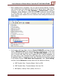
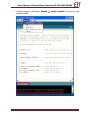
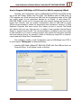
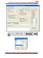
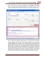
7. After installing Driver completely, user can use the device instantly. However,
user should check and adjust the values of the device first to make sure its
accuracy. In this step, go to “My Computer → Control Panel ( System (
Hardware ( Device Manager”, check Port (COM&LPT) and then see the name
of “USB Serial Port”. User has to remember this Com Port number of the
device because user needs to use it as reference when calling this function as
shown below;
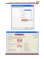
8. In this step, click sign (+) in front of Ports (COM&LPT) and then find the
device “USB Serial Port” that has already been installed Driver. If user does
not ensure that it is the device of Board “ET-EASY168 STAMP” or not, user
has to remove USB Cable first and it makes all lists of device disappear; on
the other hand, if user interfaces the USB Cable again, all lists of device must
be appeared again. If everything is OK, click Tab that is list of device names,
it will display window “USB Serial Port Properties”, click “Port Setting”
and then choose Advance to setup values into the device as follows;
a. USB Transfer Size ( Receive (Bytes): Set it as 256.
b. USB Transfer Size ( Transmit (Bytes): Set it as 128.
c. BM Option ( Latency Timer (mSec): Set it as 1.
ETT CO., LTD
-12-
WWW.ETT.CO.TH
User’s Manual of Board Micro Controller ET-EASY168 STAMP
↓
ETT CO., LTD
-13-
WWW.ETT.CO.TH
User’s Manual of Board Micro Controller ET-EASY168 STAMP
Development of ET-EASY168 STAMP in the format of Arduino Project
Normally, Board ET-EASY168 STAMP has already been installed Program Boot
Loader
completely.
It
uses
Program
Boot
Loader
named
“BOOT_EASY168_AUTO.HEX” that is the original of Arduino and it is edited by
ETT, especially the part of condition of application to be corresponding with the
Hardware System of Board ET-EASY168 STAMP better. This Program Boot Loader is
used to communicate and command to Upload Code from Computer PC into MCU on
board without using external programmer. The specifications of Program Boot
Loader that are additionally edited by ETT are described below;
-
Communicate with external programmer through Protocol STK500
(STK500V1).
Use Baud Rate 19200 with Frequency XTAL 16MHz.
Size of Program Boot Loader is 2KByte and runs at position 0x3800-0x3FFF.
Use LED that is connected with Pin Digital-13(PB5) to display status while
Program Boot Loader is running.
Program in Boot Loader always runs automatically after reset and MCU always
starts running in this Boot Loader first. If there is no any communication from
Program Arduino within 5 seconds, MCU will leave Boot Loader to start
running in user’s commands automatically. While Boot Loader is running, LED
that is connected with Pin Digital-13(PB5) will blink 3 times first and then ON
to wait for the command from program to Upload Code into MCU. If there is
no any communication from Program of Arduino within 5 seconds, program
will skip over to run in the beginning position in the part of the program that
is written by user instantly.
Moreover, user can use the other standard Program Boot Loader according to
program of Arduino. In this case, it uses Program Boot Loader called
“ATmegaBOOT_168_diecimila.hex” that is contained in the same Drive and
Folder that user has already installed program of Arduino that is “C:\arduino0012\hardware\bootloaders\atmega168\ATmegaBOOT_168_diecimila.he
x”.
However, it is necessary to have device that can program Code into MCU if
user wants to install Program Boot Loader Code into MCU. In this case, user can
use Programmer that has the Connector IDE 10 PIN standard “AVRISP” of ATMEL
instantly. Please see more information from “How to Program Boot Loader into
Board ET-EASY168 STAMP” at the end of this User’s Manual.
ETT CO., LTD
-14-
WWW.ETT.CO.TH
User’s Manual of Board Micro Controller ET-EASY168 STAMP
How to install Program Arduino
After installing USB Driver into board completely, it ends the procedure of
preparation. Next, it is the procedure of applying, writing and learning program as
desired. First of all, user has to install Program of Arduino to be learning program as
procedures below;
1. Unzip File name “arduino-0012-win.zip” in Hard disk; in this case, we
recommend user to unzip that file in outermost Root of Drive C. After
unzipping completely, the program is in “c:\arduino-0012”.
2. Run Program “arduino.exe” and it will display result as shown below;
ETT CO., LTD
-15-
WWW.ETT.CO.TH
User’s Manual of Board Micro Controller ET-EASY168 STAMP
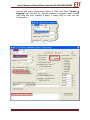
3. If using this program in the first time, user needs to setup Hardware System
that is used with program of Arduino first because nowadays there are many
hardware versions that are designed and created to use with Program
Development of Arduino. In the case of Board ET-EASY168 STAMP, please set
name of board as “Diecimila” and click Menu “Tools → Board → Arduino
Diecimila”; and then it will display result as shown below;
ETT CO., LTD
-16-
WWW.ETT.CO.TH
User’s Manual of Board Micro Controller ET-EASY168 STAMP
4. Set Com Port Number to communicate with board that must be corresponding
with Com Port Number that has already been installed Driver of USB
previously. For example, if installing Driver of USB and its Com Port Number is
COM5, click Menu “Tools → Serial Port → COM5” as shown below;
ETT CO., LTD
-17-
WWW.ETT.CO.TH
User’s Manual of Board Micro Controller ET-EASY168 STAMP
5. Test on writing program, click Menu “File → New” and type program to test
or maybe open the created example file instead. In this case, we recommend
user to test program of blinking light, click Menu “File → sketchbook (
Examples ( Digital ( Blink” and it will display result as shown below;
int ledPin = 13;
void setup()
{
pinMode(ledPin, OUTPUT);
}
void loop()
{
digitalWrite(ledPin, HIGH);
delay(1000);
digitalWrite(ledPin, LOW);
delay(1000);
}
ETT CO., LTD
-18-
WWW.ETT.CO.TH
User’s Manual of Board Micro Controller ET-EASY168 STAMP
6. Compile program, click Menu “Sketch → Verify/Compile” as shown in the
example below;
ETT CO., LTD
-19-
WWW.ETT.CO.TH
User’s Manual of Board Micro Controller ET-EASY168 STAMP
7. Download Code into board, click Menu “File → Upload to I/O Board”, wait
for a while until the operation is complete and it should display result as
shown below;
8. After Upload Code into board completely, board starts running follow the
written commands in program instantly. User can see blinking of LED that
alternates between ON and OFF at the speed of 1 second all the time.
ETT CO., LTD
-20-
WWW.ETT.CO.TH
User’s Manual of Board Micro Controller ET-EASY168 STAMP
How to Program Boot Loader into Board ET-EASY168 STAMP
Normally, Board ET-EASY168 STAMP has already been programmed Boot
Loader completely, so user can use it instantly. However, if user wants to change
the new Boot Loader or there is mistake and makes Boot Loader damaged, user can
program new Boot Loader into board. Board ET-EASY168 STAMP is designed to have
AVRISP Connector to program Code into MCU directly, so it can be connected with
all programmer versions that have connector corresponding with AVRISP standard of
ATMEL instantly. In this case, we will represent how to program Boot Loader with
programmer of ETT Version “ET-AVR ISP USB V1.0” and use Program “AVR
Studio 4” of ATMEL as described below;
1. Interface USB Cable with Board ET-EASY168 STAMP if user wants to use
Power Supply from Port USB or supply +5V Power Supply into board at Pin
28(+5V).
2. Interface USB Cable with Programmer “ET-AVR ISB USB V1” and interface
10Pin Pair Cable between AVRISP Connector of both boards together.
3. Run Program AVR Studio 4 and it will display result as shown below;
ETT CO., LTD
-21-
WWW.ETT.CO.TH
User’s Manual of Board Micro Controller ET-EASY168 STAMP
4. Click Menu “Tools → Program AVR → Connect.. → STK500 or
AVRISP”, choose Com Port Number of Programmer ET-AVR ISP USB V1
corresponding with the Driver that has already been installed previously, and
then choose Connect (in the example is Com9)as shown below;
↓
ETT CO., LTD
-22-
WWW.ETT.CO.TH
User’s Manual of Board Micro Controller ET-EASY168 STAMP
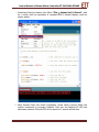
5. After connected completely, user should test on the connection. Click Tab
Main; choose the MCU number to be ATmega168; choose Programming
Mode and target Settings to be ISP Mode and then choose Read
Signature. If everything is OK, it will display results as shown below;
6. Choose Tab Program and then choose options as follows;
•
•
Device: Choose Erase device before flash programming and
Verify device after programming.
Flash:
Choose
Input
HEX
File
to
be
“BOOT_EASY168_AUTO.HEX” and then choose Program to
program Boot Loader into MCU and it will display result as shown
below;
ETT CO., LTD
-23-
WWW.ETT.CO.TH
User’s Manual of Board Micro Controller ET-EASY168 STAMP
7. After programmed Code into MCU completely, choose Tab Fuses to program
Fuse Bit into MCU and then set options as follows;
• Set BOOTSZ to be Boot Flash size = 1024 word start address =
$1C00.
• Set BOOTRST to be Enable.
• Set SPIEN to be Enable.
• Set SUT_CKSEL to be Ext.Crystal Osc 8.0MHz; Start-up time
PWRDN/RESET: 16K CK/14 that is the option at the end.
When user has already chosen all options completely, it will display result as
shown below;
8. After programmed Fuse Bit completely, choose Tab LockBits. In this case,
set Protect for particular Boot Loader only; choose BLB1 to be LPM and
SPM prohibited in Boot Section and then Program. It ends the
procedure of program Boot Loader.
ETT CO., LTD
-24-
WWW.ETT.CO.TH
User’s Manual of Board Micro Controller ET-EASY168 STAMP
How to Program USB Bridge of FTDI into Port USB for supplying 500mA
Normally, the Configuration value of USB Bridge No.FT232R from FTDI will be
set to use with Power Supply from Port USB. The standard value of USB Driver of
FTDI requests only 90mA current from USB Host but the standard value of Port USB
can supply power to the connective devices up to 500mA. If using Board ETEASY168 STAMP to test and it connects with less external device (use current not
higher than 500mA), user can modify Configuration value of USB HUB to supply
500mA current because it makes the experiment more convenient. However, if using
Notebook Computer that uses current from battery to test or connect Test Board
with device that uses very high current, it is better if user provides external Power
Supply to support board by self. This recommendation is suitable for user who wants
to test operation or to test on writing program with board and the board connects
with less external device; for example, it tests on blinking by using LED or transmitreceive data with Serial Port Communication.
The method to modify or edit Configuration value of USB Bridge from FTDI is
to use Program “MProg.exe” as described below;
1. Interface USB Cable of Board ET-EASY168 STAMP with Port USB and then run
Program MProg. It will display results as follows;
ETT CO., LTD
-25-
WWW.ETT.CO.TH
User’s Manual of Board Micro Controller ET-EASY168 STAMP
2. Command Program “mProg” to find out USB Bridge that has already been
installed, click Menu “Device → Scan” and it should display result as shown
below;
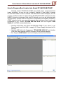
3. Read the old Configuration values of FTDI, click Menu “Tools → Read and
parse” and it should display result as shown below;
ETT CO., LTD
-26-
WWW.ETT.CO.TH
User’s Manual of Board Micro Controller ET-EASY168 STAMP
4. Modify or edit the Configuration values; set USB Power Options to be Bus
Powered and set Max Bus Power from 90 milli Amps to 500 milli
Amps. For other Configuration values, it should not be changed and then
save the new Configuration values, click Menu “File → Save As..” as shown
below;
ETT CO., LTD
-27-
WWW.ETT.CO.TH
User’s Manual of Board Micro Controller ET-EASY168 STAMP
5. Program and return Configuration values to FTDI; click Menu “Device →
Program” and then wait for until the operation is complete. Next, remove
USB Cable and then interface it again, it makes USB run with the new
Configuration.
↓
ETT CO., LTD
-28-
WWW.ETT.CO.TH
User’s Manual of Board Micro Controller ET-EASY168 STAMP
Development of d ET-EASY168 STAMP in format of AVR Microcontroller
If user wants to commonly develop program for Board ET-EASY168 STAMP in
the format of AVR Microcontroller, user can do it by choosing any language that
supports AVR MCU No.ATmega168 to write program by self. User can manage all
resource systems internal ATmega168 suitably by self; in this case, there are 2
methods as described below;
•
Program Development with External Programmer: It is good method
because it does not lose any resource; moreover, user can use and set the
desired specification of resources internal MCU by self. However, it must have
external Programmer to program Code into MCU. In this case, it can be used
with any Programmer version that supports application of MCU
No.ATmega168 and has standard AVRISP Connector of ATMEL.
•
Program Development with Boot Loader: It is good method because
user can program Code into MCU through Program Boot Loader instantly after
writing program completely without using any external Programmer.
However, there are some restrictions because it loses 2KByte Flash Memory
(0x3800-0x3FFF) that is used to store Code program to install Program Boot
Loader. Normally, Board ET-EASY168 STAMP has already been installed
Program Boot Loader completely; so, user can write program up to 14KByte
(from 16KByte totally). The position address of Code program must be written
in the range of 0x0000 to 0x37FF (0x1C00-0x1FFF K Word). For SRAM,
EEPROM and other resources internal MCU, user can use them as usual.
ETT CO., LTD
-29-
WWW.ETT.CO.TH
User’s Manual of Board Micro Controller ET-EASY168 STAMP
Example of Program Development with WinAVR by using with Boot Loader
This example is the method to develop program of ATmega168 with C
Language; in this case, it uses Program AVR Studio4 of ATMEL with C Language
Compiler of WinAVR.
1. Run Program AVR Studio4.
2. Create new project, click Menu “Project → New project” and then setup
options into program as follows;
• Set Project Type to be AVR GCC.
• Location for storing Project, please specify the desired location of Folder
to store file and Code of Project. In the example, it is
“C:\test_easy168\”.
• Specify the desired Project Name; in this example, it is “led_blink” and
then also choose Create initial file. When specified the Project name
completely, program will create file name as same as the specified project
name automatically.
ETT CO., LTD
-30-
WWW.ETT.CO.TH
User’s Manual of Board Micro Controller ET-EASY168 STAMP
3. When setup options into program completely, click Next. Set Debug
platform to be AVR Simulator and then set Device to be ATmega168 as
shown below;
↓
ETT CO., LTD
-31-
WWW.ETT.CO.TH
User’s Manual of Board Micro Controller ET-EASY168 STAMP
4. Type command of program in window Text Editor of program to test
operation. In this case, it tests with Code Program for blinking LED at PB5
that is installed on Board ET-EASY168 STAMP as shown in the example
below;
/******************************/
/* Program Test LED Blinking */
/* Board : ET-EASY168 STAMP
*/
/* MCU
: ATmega168
*/
/* X-TAL : 16.00MHz
*/
/******************************/
#include <avr/io.h>
#define F_CPU 16000000UL
#include <util/delay.h>
// X-TAL = 16 MHz
#define PORT_LED PORTB
#define DIR_LED DDRB
#define LED 5
// Port Drive LED = PB
// Port Direction
// Pin Drive LED = PB5
/********************/
/* Delay 1..65535 mS */
/********************/
void delay_ms(unsigned int time)
{
while(time-->0)
{
_delay_ms(1.0);
}
}
int main (void)
{
DIR_LED |= (1<<LED);
while(1)
{
PORT_LED &= ~(1<<LED);
delay_ms(200);
PORT_LED |= (1<<LED);
delay_ms(200);
// Pin Drive LED = Out
// Pin LED = 0
// Pin LED = 1
}
}
ETT CO., LTD
-32-
WWW.ETT.CO.TH
User’s Manual of Board Micro Controller ET-EASY168 STAMP
5. After typed Code program completely, compile program, click Menu “build →
rebuild all”. The compiling result will be HEX File that has the name as same
as the created project name as shown below;
ETT CO., LTD
-33-
WWW.ETT.CO.TH
User’s Manual of Board Micro Controller ET-EASY168 STAMP
How to Program HEX Code into Board ET-EASY168 STAMP on Boot Loader
After wrote program, compiled commands, and got HEX File completely if
user wants to program the compiled HEX Code of this program through Program
Boot Loader of board for Program Development of Board ET-EASY168 STAMP in the
format of AVR Microcontroller, we recommend user to use Program AVRDude
through AVRDudeGUI as described in procedures below;
1. Create Folder name “AVRDUDE” in Drive C (“C:\AVRDUDE\”), copy program
of avrdude and avrdudeGUI and then paste them in “C:\AVRDUDE\”. In
this case, there are 3 files; avrdude.exe, avrdude.conf and
avrdudegui.exe.
2. Run Program AVRDude.EXE, choose Tab Configuration and then setup
options as follows;
ETT CO., LTD
-34-
WWW.ETT.CO.TH
User’s Manual of Board Micro Controller ET-EASY168 STAMP
Setup Configuration values into Program AVRDudeGUI as follows;
• Location of avrdude: Choose name and location of file avrdude.exe
that is installed in the step 1; in this case, it is
“C:\AVRDude\avrdude.exe”.
• -C Location of alternate configuration file: Choose name and location
of file avrdude.conf that is installed in step 1; in this case, it is
“C:\AVRDude\avrdude.conf”.
• -p Device: Choose it to be m168.
• -c Programmer: Choose it to be stk500.
• -p Port: Choose Com Port Number corresponding with the Drive
installation of USB(FTDI).
• -b Baudrate: Set it to be 19200.
3. Go to Tab File, in the part of Flash, choose Write and Verify and then
specify the desired HEX File name for programming. In this case, it uses HEX
File from the example that is written by C Language of WinAVR and it is in
“C:\test_easy\default\led_blink.hex” as shown below;
ETT CO., LTD
-35-
WWW.ETT.CO.TH
User’s Manual of Board Micro Controller ET-EASY168 STAMP
4. When setup values into program completely, choose Execute in Tab Files.
Program avrdude starts programming HEX File into board instantly; in this
case, user needs to wait for until the operation is complete as shown below;
5. After programming completely, please wait for 5 seconds and board will start
running instantly. In this case, LED continues blinking and it alternates
between ON and OFF endlessly. If user wants to test the new operation, try
pressing RESET Switch on board and it makes LED blinking quickly 3 times
and then ON. It means that it is in progress of MCU operation in Program of
Boot Loader; if the program is not commanded to run in Program Code Mode
of Boot Loader within 5 seconds, MCU will end the operation in the part of
Boot Loader and then skip over to run in the part of Code of user instantly.
Remember after resetting, it will always run like this. Program in the part of
user starts running instantly after out of resetting status about 5 seconds.
ETT CO., LTD
-36-
WWW.ETT.CO.TH
D
C
B
6
7
8
9
VBUS
DD+
ID
GND
CN1
MINI USB
SH1
SH2
SH3
SH4
1
C1
VCC
100n
1
2
3
4
5
100n
C2 VCC
D1
PMEG4005ET
C3
100n
VCC
20
4
17
16
15
19
27
28
7
18
21
26
25
D2
SM-4004
U1
FT232R
VCC
VCCIO
3V3OUT
USBDM
USBDP
RESET#
OSC1
OSC0
GND
GND
GND
TEST
AGND
VCC
R1
4k7
LED1
PWR
TXD
RXD
RTS#
CTS#
DTR#
DSR#
DCD#
RI#
CBUS2
CBUS4
NC
NC
CBUS0
CBUS1
CBUS3
2
C4
100n
S1
RESET
VCC
R2
10k
VCC
RESET
C10
C8
100n
AREF
1
5
3
11
2
9
10
6
22pF
22pF
C9
100n
13
12
C11
23
22
14
8
24
2
29
18
20
21
7
Y1
16MHz
8
C5
100n
VCC
PC6(RESET)
AVCC
AREF
AGND
PB6(TOSC1/XTAL1)
PB7(TOSC2/XTAL2)
3
3
C6
100n
PB0(ICP1)
PB1(OC1A)
PB2(OC1B/SS)
PB3(MOSI/OC2A)
PB4(MISO)
PB5(SCK)
PC0(ADC0)
PC1(ADC1)
PC2(ADC2)
PC3(ADC3)
PC4(ADC4/SDA)
PC5(ADC5/SCL)
ADC6
ADC7
PD0(RXD)
PD1(TXD)
PD2(INT0)
PD3(INT1/OC2B)
PD4(T0/XCK)
PD5(T1/OC0B)
PD6(AIN0/OC0A)
PD7(AIN1)
23
24
25
26
27
28
19
22
12
13
14
15
16
17
D0/RX
D1/TX
D2
D3
D4
D5
D6
D7
A0
A1
A2
A3
A4
A5
A6
A7
D8
D9
D10
D11
D12
D13
R5
1k
30
31
32
1
2
9
10
11
R4
1k
Number
1
3
5
7
9
2
4
6
8
10
CN2
AVR ISP
R3
4k7
D0/RX
D1/TX
D2
D3
D4
D5
D6
D7
D8
D9
D10
D11
D12
VCC
D13
4
4
Sheet of
Drawn By:
LED2
J1
1
2
3
4
5
6
7
8
9
10
11
12
13
14
10-Nov-2008
C:\ET-Easy168ST\ET-Easy168ST.Ddb
U2
ATMEGA168-TQFP32
Title
A4
Size
Date:
File:
J2
AREF
D13
RESET
A0
A1
A2
A3
A4
A5
A6
A7
C7 VCC
D3
10uF
1
2
3
4
5
6
7
8
9
10
11
12
13
14
Revision
PMEG4005ET
A
1
6
VCC
GND
5
4
VCC
GND
3
VCC
VCC
D
C
B
A