1
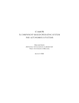
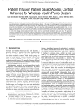
D E L AY 2 5 M AN U AL
P R E L I M I N AR Y
Delay25
A 4 channel ½ ns programmable delay line
H. Correia, A. Marchioro, P. Moreira
and
J. Schrader
CERN - EP/MIC, Geneva Switzerland
2004-12-15
Version 1.0
Technical inquires: [email protected], [email protected]
VERSION 1.0
1
D E L AY 2 5 M AN U AL
P R E L I M I N AR Y
Introduction__________________________________________________ 4
Features: .............................................................................................................................4
OPERATION _________________________________________________ 4
Operating the ASIC ___________________________________________ 6
IO mode ...............................................................................................................................6
I2C register access ............................................................................................................6
Control registers ................................................................................................................6
Channel control registers CR0, CR1, CR2, CR3 and CR4 ...........................................7
General control register GCR ........................................................................................7
Timing..................................................................................................................................8
pinout_______________________________________________________ 8
References __________________________________________________ 9
VERSION 1.0
2
D E L AY 2 5 M AN U AL
P R E L I M I N AR Y
Summary of Changes
Version 1.0:
•
First release of the Delay25 manual 2004-12-15
VERSION 1.0
3
D E L AY 2 5 M AN U AL
P R E L I M I N AR Y
INTRODUCTION
The Delay25 is a 5 channel CMOS programmable delay line featuring 4 channels that
allow to phase delay periodic or non-periodic digital signals and a master channel that
can be used to phase delay a clock signal. The master channel serves as a
calibration reference. The phase of each channel can be independently programmed
with a resolution of 0.5 ns through an I2C interface [1]. The reference clock frequency
can be any of the following: 32, 40, 64 or 80 MHz.
The ASIC is manufactured in a 0.25 µm CMOS radiation tolerant technology.
Features:
•
0.25 µm CMOS technology
•
Radiation tolerant
•
Self calibrating
•
Reference clock frequencies: 32, 40, 64 or 80 MHz
•
Phase resolution: 0.5 ns
•
Output jitter: < xxxxxx ps
•
Programmable I/O:
o
CMOS 2.5V
o
LVDS
•
Supply voltage: 2.5 V
•
Package: TQFP32
OPERATION
A block diagram of the delay25 ASIC is shown in Figure 1. The ASIC contains a
master Delay Locked Loop (DLL), four Replica Delay Lines (RDL), an I2C interface
and double standard I/O input and output buffers.
In the circuit, the DLL serves as a control element for the replica delay lines. In short,
a delay locked loop is a control loop that regulates the total propagation delay of a
clock signal across a voltage controlled delay line. The control loop assures that the
total propagation delay is exactly equal to a clock period (or a multiple of it). By taping
the signal along the delay line at regular intervals it is possible to obtain precisely
calibrated delays which are a fraction of the clock period. Since the DLL uses a
reference clock to calibrate the total propagation delay its operation is rendered
independent of the fabrication process parameters, temperature and power supply
voltage (within the operation ranges). The four replica delay lines are physically
made as exact copies of the voltage controlled delay line that is part of the DLL.
Under these conditions, and due to the good matching that is possible to obtain in
integrated circuits, when the control voltage produced by the DLL is applied to the
replica delay lines, their total propagation delay will be identical to that of the master
delay line. Again, by taping these replica delay lines at periodic intervals it is possible
to obtain calibrated delays which are a fraction of the reference clock period. There
are two main differences between the master and the replica delay lines: first, the
master delay line is part of a control loop, that is, its total delay is constantly
monitored and corrected, while the replica delay lines are working open loop. Second,
VERSION 1.0
4
D E L AY 2 5 M AN U AL
P R E L I M I N AR Y
the master delay line requires a periodic (clock) signal for correct operation of the
control loop while the replica delay lines can be used with non-periodic signals
(pulses) since they are working open loop. As said before calibration of the replica
delay lines depends on matching, which for integrated circuits is normally quite good
but not exactly perfect. This means that the total delay of the replica delay lines is not
going to be exactly equal to that of the master and so there will be some small errors
introduced. However, these errors should be well with the system requirements and
specifications.
In0
Replica Delay Line
In0
Out0
Out0
Replica Delay Line
In1
D0
In1
Out1
D1
Out1
Master DLL
CLKIN
ClockIn
CLKOUT
ClockOut
Replica Delay Line
In2
In2
Out2
Out2
Replica Delay Line
In3
D2
In3
Out3
Out3
IOMODE
Delay25
DC
I2C Interface
D3
D0, D1, D2 D3 and DC are independently programable delays
I2C Bus I2C Address
Figure 1 Block diagram of the delay25 (left) and hypothetical use of the ASIC
illustrating the meaning of the phase delay for each channel (right)
Figure 1 (right) illustrates a possible use of the delay25 chip and the meaning of
phase delay for each channel. As mentioned before, please note that the master
channel can be only used with a clock signal having clock frequencies of 32, 40, 64 or
80 MHz.
The IOMODE configuration pin allows the ASIC to operate with either CMOS (2.5V)
or LVDS [2] levels. The reset and I2C related pins are not affected by the IOMODE
signal.
VERSION 1.0
5
D E L AY 2 5 M AN U AL
P R E L I M I N AR Y
OPERATING THE ASIC
The ASIC operation is controlled by the IOMODE pin and by means of four internal
registers, which can be accessed through an I2C bus.
IO mode
The IO signal levels are controlled by the pin IOMODE (IO mode) as is indicated in
Table 1. As represented in Figure 1 the IO mode pin affects only the input and output
buffers of the replica and master delay lines. When the IO mode is set to CMOS (0)
all the channels inputs and outputs work single ended being all the negative inputs
and outputs disabled. When IO mode is set to LVDS (1) all the channels inputs and
outputs are differential.
Table 1 IO modes
IOMODE
Function
0
CMOS 2.5 V
1
LVDS
I2C register access
The ASIC registers are accessed through the I2C bus which is composed of the
following signals: SCL (serial clock), SDA (serial data) and the address pins
I2CA<6:3> which correspond to the four most significant bits of the I2C address
(these act a chip select address). The three least significant bits of the I2C address
are internally decoded and map into the ASIC internal register as shown in Table 2.
Table 2 Internal I2C register map
I2C Address
Name
Function
0
CR0
Control register for channel 0
1
CR1
Control register for channel 1
2
CR2
Control register for channel 2
3
CR3
Control register for channel 3
4
CR4
Control register for clock channel
5
GCR
General control register
6
Unused
-
7
Unused
-
Control registers
Five register control the operation of the Delay25 ASIC. Each channel is individually
controlled by its control register (CR0 to CR4). A general control register (GCR)
controls global parameters for all the five channels, the DLL and the logic.
VERSION 1.0
6
D E L AY 2 5 M AN U AL
P R E L I M I N AR Y
Channel control registers CR0, CR1, CR2, CR3 and CR4
The bit allocation of each channel control register is as given in Table 3. Bits
Del<5:0> control the delay for each channel and the Enable bit enables the channel
output. Upon a reset, bit Enable and bits Del<5:0> are cleared.
Table 3 Control registers (CR0 to CR4) bit allocation
B7
B6
B5
B4
B3
B2
B1
B0
n.u.
Enable
Del<5>
Del<4>
Del<3>
Del<2>
Del<1>
Del<0>
Function
n.u.
0
0
0
0
0
0
0
Reset State
General control register GCR
The general control register GCR controls the operation of the Delay-Locked Loop
(DLL) and allows to reset the DLL or the ASIC via the I2C interface. The bit allocation
for this register is given in Table 4
Table 4 General Control Register (GCR) bit allocation
B7
B6
B5
B4
B3
B2
B1
B0
GRST
IDLL
n.u.
n.u
n.u.
n.u.
M<1>
M<0>
Function
0
0
-
-
-
-
Not
Not
Reset State
cleared
cleared
The ASIC can operate with for different clock frequencies (32, 40, 64 and 80 MHz).
Correct operation of the ASIC requires bits M<1:0> of the control register to be set to
the appropriate mode. The settings of these bits should be made according to Table
5. Bits M<1:0> are not affected by a reset.
Table 5 Clock modes
M<1>
M<0>
Clock Frequency [MHz]
0
0
40
0
1
80
1
0
32
1
1
64
IDLL: bit IDLL is used to force the resynchronization of the DLL without resetting the
chip. Writing a “1” to this bit forces the resynchronization of the DLL. This bit always
reads as a “0”
GRST: bit GRST is used to reset the ASIC and force the synchronization of the DLL.
The action of this bit is similar to a hardware reset. That is, the contents of the control
register are cleared but the contents of the general control register remains
unchanged (clock mode bits unaffected). This bit always reads back as a “0”.
VERSION 1.0
7
D E L AY 2 5 M AN U AL
P R E L I M I N AR Y
Timing
Data in preparation
PINOUT
The ASIC is package in a 32 pin TQFP package. Pins are assigned as indicated in
Table 6.
Table 6 Pins assignments
Pin number
Pin name
IO levels
Function
1
Vdd
+2.5 V
Power
2
SCL
CMOS
I2C serial clock
3
SDA
CMOS – open drain
I2C serial data
4
I2CA6
CMOS
I2C Address
5
I2CA5
CMOS
I2C Address
6
I2CA4
CMOS
I2C Address
7
I2CA3
CMOS
I2C Address
8
GND
0V
Ground
9
OUT0+
LVDS/CMOS
Channel 0 +output
10
OUT0-
LVDS
Channel 0 -output
11
OUT1+
LVDS/CMOS
Channel 1 +output
12
OUT1-
LVDS
Channel 1 -output
13
OUT2+
LVDS/CMOS
Channel 2 +output
14
OUT2-
LVDS
Channel 2 -output
15
OUT3+
LVDS/CMOS
Channel 3 +output
16
OUT3-
LVDS
Channel 3 -output
17
Vdd
2.5 V
Power
18
IOMODE
CMOS
IO mode select
19
ResetZ
CMOS
Reset – active low
20
CLKOUT-
LVDS
Clock channel 4 -output
21
CLKOUT+
LVDS/CMOS
Clock channel 4 +output
22
CLKIN-
LVDS
Clock channel 4 -input
23
CLKIN+
LVDS/CMOS
Clock channel 4 +input
24
GND
0V
Ground
25
IN3-
LVDS
Channel 3 -input
26
IN3+
LVDS/CMOS
Channel 3 +input
27
IN2-
LVDS
Channel 2 -input
VERSION 1.0
8
D E L AY 2 5 M AN U AL
P R E L I M I N AR Y
28
IN2+
LVDS/CMOS
Channel 2 +input
29
IN1-
LVDS
Channel 1 -input
30
IN1+
LVDS/CMOS
Channel 1 +input
31
IN0-
LVDS
Channel 0 -input
32
IN0+
LVDS/CMOS
Channel 0 +input
REFERENCES
[1] The I2C-BUS Specification:
http://www.semiconductors.philips.com/acrobat_download/literature/9398/39340011.pdf
[2] See for example: http://www.national.com/an/AN/AN-971.pdf
VERSION 1.0
9