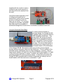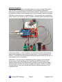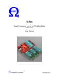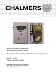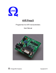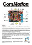
1
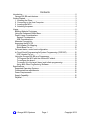
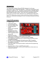
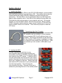
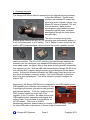
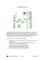
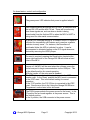
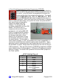
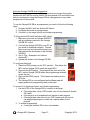
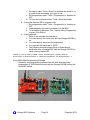
Omega-328 SB Rapid Prototyping tool with Shield Base for Atmel AtmegaXX8 Microcontrollers User Manual - Omega MCU Systems Copyright 2012 Contents Introduction ........................................................................................................... 2 Omega-328 SB main features: .......................................................................... 2 Getting Started ...................................................................................................... 3 1. Installing the Driver ....................................................................................... 3 2. Connecting to the Host Computer ................................................................ 3 3. Inserting the MCU ........................................................................................ 3 4. Attaching the power ...................................................................................... 4 Usage ................................................................................................................... 5 Building Modular Prototypes ............................................................................. 5 Using the Enhanced Shield Base ...................................................................... 6 Power Usage Considerations ............................................................................ 7 General Considerations ................................................................................. 7 USB Considerations ...................................................................................... 7 Alternate Connectivity ....................................................................................... 8 Accessing the MCU I/O ..................................................................................... 9 SVG Header Pin Mapping.............................................................................. 9 Shield Base Pin-out ..................................................................................... 10 On board status, control and configuration ...................................................... 11 In Circuit Serial Programming/In System Programming (ICSP/ISP) ................ 12 ICSP Header Pin-out ................................................................................... 12 Using the Omega-328 SB as a Programmer ................................................... 13 To Program the MCU with the ArduinoISP sketch: ...................................... 13 To configure the board: ................................................................................ 13 To connect it to the target (slave) and initiate programming: ....................... 13 Using With Other Programming Software .................................................... 14 Specifications ...................................................................................................... 15 Supported Operating Systems ........................................................................ 15 Communications requirements ........................................................................ 15 Power Requirements ....................................................................................... 15 Supply Capability............................................................................................. 15 Physical ........................................................................................................... 15 - Omega MCU Systems Page 1 Copyright 2012 Introduction The Omega MCU Systems Omega-328 SB is designed to be the very embodiment of rapid, reliable and repeatable. It gives you everything you need to bring your creations to life. The ability to use both Arduino compatible shields along with modular sensors and actuators means you can have your prototypes built and ready for code in no time. Add to that 100% compatibility with the Arduino IDE, a ZIF MCU socket, ergonomic size, a brawny power supply and a 6-pin ICSP header and you have a unique combination of benefits consisting of ease of use, professional handling and a level of versatility that takes a back seat to no one. Omega-328 SB main features: Tough 1.6mm FR4 PCB 16MHz Crystal 1 amp power supply D13 LED disable option Auto-reset disable option Configurable power options Arduino UNO compatible shield base Designed for the Atmel AtmegaXX8 MCU family 100% compatible with the Arduino IDE Alignment-correcting header allows standard 0.1" proto-board for DIY shields SVG headers on all signals for 3-wire sensor/actuator modules ICSP programmer mode allows you to use the Omega-328 SB as a avrisp compatible programmer SI Labs CP2103 USB bridge for high performance USB 2.0 capability Zero Insertion Force (ZIF) MCU socket for ease of handling and reduced wear and tear on the MCU 6 pin ICSP header for burning bootloaders, loading code and programming other devices Standard 5.5mm x 2.1mm coaxial DC power socket. DuPont style wire jumpers can be used for attachment to other circuits or a solderless breadboard - Omega MCU Systems Page 2 Copyright 2012 Getting Started 1. Installing the Driver The Omega-328 SB uses a Silicon Labs CP2103 USB bridge for communication and downloading sketches from the Arduino IDE. This requires that a driver be installed before the Omega-328 SB is attached to the host computer and powered up. The latest driver can be downloaded either from the Downloads page at www.omegamcu.com or from Silicon Labs website at www.silabs.com. Download the driver setup program to your computer and run it. We strongly suggest you use the default options, and follow the prompts. Before clicking “Finish” during the install procedure, make sure the ”Launch the CP210X VCP Driver Installer” check box is checked. Then follow the prompts to install the VCP driver. 2. Connecting to the Host Computer The Omega-328 SB is equipped with a standard USB “B” connector and can connect to a host computer using a standard USB “A to B” cable as shown (not included). The Omega-328 SB will not be discovered by the computer until the power is applied as in step 4 or configured to be powered from the USB port. OMS recommends you use as short a USB cable as you can. 3. Inserting the MCU In order to reduce wear and tear on your microcontroller chips and increase usability and accessibility, the Omega-328 SB is equipped with a zero insertion force (ZIF) socket. To place an MCU into the socket make sure the lever is in the vertical position then place the chip into the socket as shown with its pin 1 adjacent to the lever. Steady the board and lower the ZIF socket lever to just past horizontal into the locked position. This will clamp the microcontroller into place. Removal of the chip is achieved by returning the lever to the vertical position. - Omega MCU Systems Page 3 Copyright 2012 4. Attaching the power The Omega-328 SB can either be powered from an external source (preferred) or from the USB port. The on-board regulator and standard DC power jack allow for a variety of power options. Any filtered DC source of between 7.5V and 23V can be used. Make sure the chosen power supply delivers positive voltage through the center conductor and negative through the outer sleeve as shown here. The most convenient and popular external power sources are a 9V AC-DC switching type (switchmode) adapter, a 6-cell ‘AA’ battery pack, or a 9V battery. The 9v battery, if used, should only be used for MCU programming as it does not have the current capability to power shields or modules. The 9V AC-DC switching type (switchmode) adapters are preferred over the transformer type adapters and batteries as they provide a more stable supply, are lighter, take up less space and are generally enormously less expensive to use. With the USB cable connecting the Omega-328 SB to the host, and the MCU inserted, apply the power by connecting the chosen power source. At this point Windows will detect the USB bridge, install the virtual com port driver and assign a com port number. Use Device Manager to determine which com port was assigned. This will be needed to properly configure the Arduino IDE. Alternatively, the Omega-328 SB can be configured to use USB supplied power. USB capability is provided as a convenience for use in prototyping low power consumption and generally well-behaved projects. To do this, simply move the PSEL jumper, located just to the right of the regulator, to the ‘U’ position. Be aware though, that USB supplied power, especially under higher and varying loads, is not as stable or as reliable as an AC-DC adapter. This is true of all MCU development platforms, despite claims to contrary or lack of warning. See more on using USB power in the section on Power Usage Considerations. - Omega MCU Systems Page 4 Copyright 2012 At this point you are ready to begin downloading programs (sketches) to your MCU. The Omega-328 SB has been designed to work with the Arduino IDE, which is available at http://arduino.cc/hu/Main/Software. Download and install the Arduino IDE according to the instructions provided on the Arduino site. Be sure to choose a board type that is compatible with the bootloader on your microcontroller and the com port that was assigned by Windows when the Omega-328 SB was attached to the host and powered up. If you purchased your Omega-328 SB with an Atmega328 microcontroller supplied from an authorized OMS dealer, it will have an Arduino Duemilanove bootloader pre-loaded. If this is the case, choose a board type of Duemilanove in the Arduino IDE. Usage Building Modular Prototypes One of the main design features of the Omega-328 SB is the ability to directly attach sensor and actuator modules without any additional circuitry or connectivity boards. These modules, commonly know as ‘bricks’, use a 3-wire connection to the host controller. The three wires carry Signal, supply Voltage and Ground, and terminate in a standard 3-pin header connector on 0.1” centers. These can be directly attached to the headers on the Omega-328 SB where each signal from the MCU is brought out and mated with a 5v and ground pair. As indicated by the markings on the headers (S, V and G), signal is the pin closest to the MCU socket, supply voltage is in the middle and ground is on the outside. Generally speaking, the connectors are not keyed and there is no discernable standard to the coloring of the wires. However, White – Signal, Red – Voltage, Black – Ground is a common pattern. As well, placing Voltage between Signal and Ground virtually assures that damage to a module is unlikely. That not withstanding, it is advisable to consult the documentation - Omega MCU Systems Page 5 Copyright 2012 supplied with the module to ensure connections are made properly so that they will function properly from the start. Using this modular approach, proof of concept prototypes can be assembled in mere minutes and the process of writing the code can begin just as quickly. The resulting prototypes are portable, repeatable and robust and not susceptible to accidental damage like circuits built on a solderless breadboard circuit are. Using the Enhanced Shield Base To further enhance flexibility in prototype design, the Omega-328 SB is equipped with an enhanced Arduino UNO compatible shield base. This means that it will accept any shield module that is designed the Arduino UNO or any earlier full-sized Arduino board. Shields can only be inserted one way. The six pin male header of the shield must be aligned with the 6 pin female header on the shield base of the Omega-328 SB. Be careful to make sure all other pins are aligned properly before pushing the shield into the shield base. The pin spacing of the standard Arduino shield base does not follow standard 0.1” spacing. The two larger female headers (H5 and H4 on the Omega 328 SB) are placed 0.16” apart to aide the proper alignment of shields. However, this makes it difficult to use standard perf-board to make homebrew shields. To eliminate this problem the Omega-328 SB has enhanced the standard shield base by adding a second female header at H5 that conforms to a standard 0.1” grid. - Omega MCU Systems Page 6 Copyright 2012 Power Usage Considerations General Considerations With a Vin of 9V, the Omega-328 SB power supply is capable of supplying up to 500mA in free air* and up to 1 Amp with adequate additional heat sinking. 1 Amp of current should easily be enough to meet needs of any number of sensors, as these generally have small power requirements. Actuators and some shields, on the other hand, such as motors, servos, buzzers, etc., generally have much higher power needs. Some planning and common sense are required in this respect. Small servos, motors and relays are generally okay if proper noise suppression is a part of their design. However, it is advisable to know and take heed of the specifications and the nature of the loads presented by actuators and shields. In particular, larger motors, servos, relays, solenoids and other inductive loads can have very large peak current demands and are not suited to direct attachment to the Omega-328 SB. This is especially true if power hungry shields are in use at the same time. In these cases, it is recommended that isolated driver boards or relays be utilized and that a separate power source be provided for the heavy loads. Generally, the more you add on, the more power you will be consuming and it is a good idea to keep track of power consumption USB Considerations When using USB power with any microcontroller development board (not just ours) you need to pay particular attention to load and load characteristics. The USB cable length should always be kept to a minimum to reduce resistance. The resistance in long cables can cause unacceptable voltage drops with high loads or unstable supply when loads vary. Take particular note of your computers specified USB port current supply capability. Never try to use more than 75% of that capability. You should never attempt to use USB power with project that has a current draw above 75% of the USB port rating or with inductive loads like motors and servos. Surges, spikes and high loads can cause ‘brown-outs’ and other noise that will affect the MCU. These conditions can cause ADC readings to be adversely affected, un-expected logic states to be read, un-expected interrupt triggers, brown out detection in the MCU can cause a program reset. Any number and kind of baffling behavior can result from unstable power. If the prototype you are working on exhibits unusual behavior under load with USB power, switching to a good 9V AC-DC adapter will generally clear up the problem. Remember, USB capability is provided as a convenience for use in prototyping low power consumption and generally well-behaved (no inductive or surge loads) projects. *(CAUTION: The regulator can get very warm under these conditions) - Omega MCU Systems Page 7 Copyright 2012 Alternate Connectivity The system of SVG headers and shield base used on the Omega-328 makes it very versatile in connecting to environments to be sensed and controlled. Almost any imaginable scenario can be accommodated. Should there be a need to interface a custom or non-modular circuit, you may need to attach the Omega328 SB to another device or a breadboard for. This can easily be accomplished using ‘Dupont’ style female to male or female to female jumpers like those shown in the picture above. In fact, as shown, you can build prototypes with modules, shields and breadboard circuits all at the same time or in any combination you choose. Just make sure that the power needs are tracked so that you do not run into problems due to overloading. Remember, if you are using a breadboard circuit as a part of your prototype project keep in mind that the ground of the Omega-328 SB will need to be properly connected to the off-board circuit’s ground to ensure a good voltage reference and a suitable return path for power and signals. Failure to provide this may result in some very strange and difficult to diagnose behavior of the combined circuit. - Omega MCU Systems Page 8 Copyright 2012 Accessing the MCU I/O When inserted into the Omega-328 SB all the I/O pins of the MCU map to the SVG headers. D8 though D13 as well as AREF are brought to the header to the upper right of the MCU socket (H1), D0 through D7 are brought to the header to the lower right (H2) and A0 through A5 are brought to the header to the left (H3). The table below shows how these header signals are mapped to the microcontroller. SVG Header Pin Mapping Omega-328 SB SVG Header pin DO Header D1 D2 3 (PD1 / TXD) H2 D3 D4 D5 D6 D7 D8 D9 D10 D11 D12 D13 Atmega MCU pin 2 (PD0 / RXD) H1 4 (PD2 / INT0) 5 (PD3 / INT1 / OC2B) 6 (PD4 / XCK / T0) 11 (PD5 / T1 / OC0A) 12 (PD6 / AIN0 / OC0B) 13 (PD7 / AIN1) 14 (PB0 / ICP) 15 (PB1 / OC1A) 16 (PB2 / SS / OC1B) 17 (PB3 / MOSI / OC2A) 18 (PB4 / MISO) 19 (PB5 / SCK) A0 23 (PC0 / ADC0) A1 A2 A3 A4 A5 AREF 24 (PC1 / ADC1) 25 (PC2 / ADC3) 26 (PC3 / ADC3) 27 (PC4 / ADC4 / SDA) 28 (PC5 / ADC5 / SCL) 21 (AREF) H3 H2 Note Note that this signal is monitored by the red RX LED while communicating through the USB port Note that this signal is monitored by the blue TX LED while communicating through the USB port - Omega MCU Systems Page 9 PWM capability PWM capability PWM capability PWM capability PWM capability PWM capability D13 is also connected to the yellow D13 LED through a 1K resistor on the Omega328 SB. This LED can be disconnected by removing the LEDD jumper. Copyright 2012 Shield Base Pin-out The Omega-328 SB shield base in comprised of headers H4 – H7 and follows precisely the standard Arduino UNO pin-out. Refer to the SVG Header Pin Mapping table above for functions and MCU Mapping. An additional header at H5 on a standard 0.1” grid and that duplicates the signals D8 – SCL, is provided to support the building of homebrew shields on standard perf-board. Not mentioned in the table above are the following: The 3V3 output is a 100ma 3.3V power source supplied via the CP2103 USB bridge The 5V power output is connected to the board’s main power supply GND pins are connected to the board’s ground Vin is connected to the input of the main regulator Reset is connected to the MCU reset pin (pin 1) SDA is connected to Pin 27 of the MCU and to A4 SCL is connected to pin 28 of the MCU and to A5 - Omega MCU Systems Page 10 Copyright 2012 On board status, control and configuration The green power LED indicates that power is applied when lit. Data communication through the MCU’s UART is monitored with the red RX LED and the blue TX led. These will be active any time those signals are, such as when a sketch is being downloaded from the Arduino IDE or when the MCU’s UART is being used for other serial communication. A yellow LED, attached through a 1K resistor to the D13 signal is included for compatibility with Arduino and is used as a generic indicator in many cases. For instance, the Duemilanove bootloader blinks this LED to indicate it is active. It can be disconnected to eliminate loading on the D13 signal whenever desired by removing the LEDD jumper. If a reset is required, pressing the Reset button located at the upper right-hand side of the Omega-328 SB will initiate a hard reset of the MCU. The ARD jumper is used to control the automatic reset. With the jumper on, the MCU will be reset when the software opens the virtual com port to begin communication via the USB port. This is the default position for normal operation. With the jumper off, the auto reset is disabled. The RSEL jumper selects which signal is sent to the ICSP header reset. In the ‘Reset’ position the MCU reset is connected to the ICSP reset. This is the default setting for normal operation. In the ‘D10’ position, the D10 I/O line is connected to the ICSP reset. See more on this in the ‘Using the Omega-328 SB as a Programmer’ section later in this document. The PSEL jumper selects the power source for the board. In the ‘R’ position the on-board regulator is the power source. This is the default position. In the U position, the USB connector is the power source. - Omega MCU Systems Page 11 Copyright 2012 In Circuit Serial Programming/In System Programming (ICSP/ISP) ICSP, or ISP (In System Programming) is a method by which an MCU (an AVR in this case) can be directly programmed while still in a circuit. In the AVR world, the programmer is known as the master and the chip to be programmed as the slave. The signals used are MOSI (Master Out – Slave In), MISO (Master In – Slave Out) and SCK (Serial ClocK) which is supplied by the master, or programmer. Add to this a reset line from the master, to reset the MCU to ready it for data transfer, Vcc by which the master can power the MCU, and a ground and you have all the signals of a standard AVR ISP interface. The Omega-328 SB provides a standard pin-out 6 pin ICSP header. This can be used, in conjunction with an external ICSP programmer, such as the OMS AVR Prog-S, to program the MCU directly. Since the ICSP protocol is built into the Atmega chips used on these boards, it is not dependant on using the bootloader and does not require the serial interface. For this reason, it can be used to program, or ‘burn’, a bootloader onto a new or erased MCU. It can also be used an alternative method of getting code onto the MCU. This is particularly useful in cases where the code is larger than will fit onto the MCU if the bootloader is present. Simply erase the chip and burn the code on using an ICSP programmer. There are many dozens of ICSP/ISP programmers available and an equal number of software options. AVRdude and PonyProg are popular and free of charge. For normal ICSP operation, be sure the RSEL jumper is in the ‘Reset’ position. ICSP Header Pin-out Pin Function 1 MISO 2 Vcc 3 SCK 4 MOSI 5 Reset (D10 in programmer mode) 6 - Omega MCU Systems GND Page 12 Copyright 2012 Using the Omega-328 SB as a Programmer This is advanced usage and we highly recommend you become thoroughly familiar with AVR MCUs and the Arduin IDE and general AVR and Aduino lore before venturing into using the Omega-328 as a programmer or any other programmer for that matter. To use the Omega-328 SB as a programmer you need to follow the following steps. 1. Program the MCU with the ArduinoISP sketch 2. Configure the board as a programmer 3. Connect it to the target (slave) and initiate programming To Program the MCU with the ArduinoISP sketch: 1. Make sure you have an Atmega-328 MCU with a bootloader inserted in the Omega328 SB ZIF socket 2. Connect the Omega-328 SB to your PC as you would to download a sketch. Choose the correct port and choose the board type that matches the bootloader in the Atmega328 MCU. 3. Got to ‘File > Examples’ and choose ArduinoISP 4. Upload this sketch to the Omega-328 SB To configure the board: 1. Place the RSEL jumper on the ‘D10’ position. This allows the MCU on the Omega-328 to reset the target MCU 2. Remove the ARD jumper. This prevents the auto rest of the MCU on the Omega-328 SB when the programming software opens the port. 3. Remove the LEDD jumper. This lessens the loading on the SCK line. 4. The Omega-328 is now configured as the Master and will supply power and programming data to the slave. To connect it to the target (slave) and initiate programming: 1. Use the ICSP on the Omega-328 to connect to the target a. If the target has a 6 pin ICSP header, use a 6 wire female to female IDC cable. b. If the target is on a breadboard use female to male jumpers c. If the target has other than a 6 pin ICSP header you will need to use appropriate jumpers or make up a special cable for the purpose. 2. To initiate programming a. If using the Arduino IDE to burn a bootloader - Omega MCU Systems Page 13 Copyright 2012 i. Set board under ‘Tools > Board’ to whatever the board is, or a board whose bootloader you want to use. ii. Set programmer under ‘Tools > Programmer’ to ‘Arduino as ISP’ iii. To burn the bootloader select ‘Tools > Burn Bootloader’ b. If using the Arduino IDE to program code i. Set programmer under ‘Tools > Programmer’ to ‘Arduino as ISP’ ii. Load the sketch you wish to program into the MCU iii. To upload the code select ‘File > Upload Using Programmer’ or press ‘Ctrl+Shift+U’ c. If using avrdude i. Refer to the avrdude documentation ii. You must specify the virtual com port the Omega-328 SB is on iii. You must specify avrisp as the programmer iv. You must set the baud rate to 19200 v. The following command line will burn a Duemilanove bootloader onto a Atmega328P with the Omega-328 SB on com4 running ArduinoISP avrdude -P com4 -b 19200 -p m328p -c avrisp -Ulock:w:0x0F:m -Uhfuse:w:0xDA:m Ulfuse:w:0xFF:m -Uefuse:w:0x05:m -V -Uflash:w:ATmegaBOOT_168_atmega328.hex:i –u Using With Other Programming Software Generally, any programming software that will work with the avrisp programmer at 19200 baud will work with the Omega-328 SB running the ArduinISP sketch. - Omega MCU Systems Page 14 Copyright 2012 Specifications Supported Operating Systems The CP2103 USB bridge driver supports the following operating systems: Windows XP Windows 2003 Windows Vista Windows 7 Communications requirements Interface Type: USB 2.0 Connection: Standard USB “B” Power Requirements Supply Voltage: Supply Current: 7.5V – 23V DC Typically between 38mA and 42mA with the MCU only while running the Duemilanove bootloader Supply Connector: 5.5mm x 2.1mm center positive co-axial jack NOTE: Supply voltage should never exceed 24V dc. Observe polarity – this board requires a center positive supply. Check before attaching the power source. Supply Capability Main Board Voltage: Max current: Free-air current: Low Voltage Supply: 5V (4.8V – 5.2V) 1A (with adequate additional heat sink) Approx. 500mA @ Vin = 9V (no added heat sink) 3.3V @ 100mA Physical Length: Width: Height: Mounting: Weight: Operating Temp. 124mm 71mm 15mm 63mm x 108.6mm 60g 0oC – 85oC Note: Arduino is a trademark of the Arduino project team. OMS PO Box 74 Bracebridge, ON, P1L 1T5 Canada - Omega MCU Systems Page 15 Copyright 2012