1
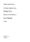
Oakley Sound Systems
5U Oakley Modular Series
ADSR/VCA
Looping Envelope Generator
User Manual
V4.0.2
Tony Allgood B.Eng
Oakley Sound Systems
CARLISLE
United Kingdom
The single width ADSR/VCA module in Moog Unit (MU) compatible format.
2
Introduction
This is the User Manual for the issues 3 and 4 of the ADSR/VCA 5U module from Oakley
Sound.
This document contains an overview of the operation of the unit, the various connections that
can be made and all the calibration procedures.
For the Builder's Guide which contains a basic introduction to the board, a full parts list for
the components needed to populate the boards, and a list of the various interconnections
please visit the main project webpage at:
http://www.oakleysound.com/adsr.htm
For general information regarding where to get parts and suggested part numbers please see
our useful Parts Guide at the project webpage or http://www.oakleysound.com/parts.pdf.
For general information on how to build our modules, including circuit board population,
mounting front panel components and making up board interconnects please see our generic
Construction Guide at the project webpage or http://www.oakleysound.com/construct.pdf.
The issue 4 VC-ADSR/VCA board mounted behind a natural finish MOTM size Schaeffer panel. Note the
two 0.1” KK headers on the lower right. These headers can be attached to the 1U Upgrade module to
allow for full voltage control of the modules four parameters.
3
The Oakley Looping ADSR/VCA Module
This is a very popular dual purpose module. Not only does it feature a looping four stage
envelope generator, but it also has a high quality voltage controlled amplifier onboard.
Two outputs are provided, one, labelled ADSR, is the raw output of the core ADSR
generator. The other, VCA OUT, is the output of the integral VCA. This highly useful circuit
implementation hard wires the ADSR generator to the control input of the VCA. The signal at
the VCA's signal input, the VCA IN socket, will then be multiplied by the ADSR waveform.
You can use any signal into this input, audio or CV. If you use CV, then the ADSR output
level will be governed by the level of the CV. If you use audio, then the ADSR waveform will
control the volume of that audio signal.
A typical use would have the IN socket being driven by the velocity CV from a midi-CV
convertor. Thus the harder you hit the keys, the greater the ADSR output level. If you use this
to control a filter sweep, this can create brilliantly effective touch sensitivity to your patch.
The circuit is configured so that if nothing is plugged into the IN socket, the VCA OUT will
behave the same as the raw ADSR output.
The ADSR is operated by a gate signal, but can also be triggered by slow rising CVs too due
to the built in Schmitt trigger function. No additional 'trig' input is required.
The ADSR/VCA module is built on one PCB called the VC-ADSR board. Although the 1U
panel design does not imply a voltage controlled design, the internal electronics are all voltage
controllable. This allows blisteringly fast minimum attack and decay times. And yet, the
controls with their true exponential response, allow you to adjust the times with ease.
Also on this module is an LED. This gives a visual indication of the output level of the internal
ADSR waveform.
The latest version of the module accommodates either our standard Oakley/MOTM power
header or a Synthesizers.com power header. For DIY builders of this module it is possible to
purchase the Sock4 circuit board which is available separately. This little board speeds up the
wiring of the four 1/4" sockets and reduces the chances of any wiring errors.
Loop Modes
The issue 3 and 4 Oakley ADSR/VCA incorporate a looping mode. Looping means that the
output will rise to the attack peak at the speed determined by the attack pot and then fall to
0.6V at the speed determined by the Decay pot. It will then rise again to attack peak and then
fall back to 0.6V and so on.
NORM - the module behaves as a standard ADSR.
GATED - the output will loop only when gate is high. As soon as gate arrives the output will
rise up at the attack speed and then decay at the decay time and repeat. If the gate is removed
at any point the output will then fall at the release time.
4
LOOP - The module's output it will loop continuously in AD mode. The Gate input has no
effect in Loop mode.
In both looping modes the position of the sustain pot can be used to turn the looping on or
off. At values above 10% the looping will stop. This is very useful in the 2U version of the
module where the looping can be controlled by an external CV.
In LOOP mode, with the sustain pot above 10%, the outputs of the module can be used as a
constant voltage source. The output voltage is determined by the position of the sustain
control; fully clockwise the voltage will be approximately +5V from both output sockets.
Upgradable Design
This module can be upgraded to full voltage control with an addition of an extra module called
the 'Four pot'. This module takes up 1U of panel space, and is fitted next to the ADSR/VCA
to be controlled. The upgrade can be added on at any time and installation is very simple. Two
small interconnects behind the front panels allow the two boards to 'talk' to each other.
5
Envelope Generators
The Oakley ADSR/VCA is my version of the classic envelope generator module. The
envelope generator or EG for short, generates a rising and then falling voltage at its output
when triggered by a gate signal. The gate is derived from a keyboard, switch or a midi-CV
convertor elsewhere in the synthesiser system. The speed of the rise in output voltage is
determined by the Attack control. The speed of the fall of the output voltage is determined by
the Decay or Release controls. The output of an EG is traditionally patched to the VCA
control voltage, to control the volume of the note when the keyboard is pressed, or to the
VCF, where it dynamically alters the harmonic structure of the sound throughout the duration
of the note played.
Traditionally there are three basic analogue EG types available:
Attack-decay (AD)
This is a one shot type of generator. The output will rise and then immediately fall. The A and
D pots determine the time taken to rise and fall. Removal of the gate will cause the decay
phase to start prematurely on most systems.
Attack-release (AR)
Very similar to the AD type, but the voltage is held high once the attack phase is completed
until the gate is removed.
Attack-decay-sustain-release (ADSR)
This one is controlled by four pots. When the attack phase is initiated by the gate signal, the
output will rise to a predetermined level. Then the decay phase starts and the output voltage
will then fall to the level set by the sustain pot. The voltage will remain at this level for as long
as the gate is high. But as soon as the gate is removed the release stage is initiated. This causes
the output to fall at a rate determined by the release pot. An ADSR EG can perform both AR
and AD operations simply by turning the sustain pot full up or down respectively.
Other types of envelope generators are available, especially on digital synthesisers, but the
three analogue types still seem to the most musician friendly.
The Oakley ADSR/VCA module also incorporates a versatile VCA on the output of the EG
core. This part is used to control or modulate the level of the EG itself. For example, a
velocity CV from the output of a midi to CV convertor, can automatically scale the ADSR
output for touch sensitive control of the VCA or VCF. This VCA has an excellent audio
response, so it can be used to modulate any audio input with the ADSR too. This combined
module used to be called an Envelope shaper, but that term has dropped out of fashion these
days. This combined module is very useful in reducing patch cords.
6
Connections
Power connections – MOTM and Oakley
The PSU power socket is 0.156” Molex/MTA 4-way header. Friction lock types are
recommended. This system is compatible with MOTM systems.
Power
Pin number
+15V
Module GND
Earth/PAN
-15V
1
2
3
4
Pin 3 on the PSU header has been provided to allow the ground tags of the jack sockets to be
connected to the powers supply ground without using the module’s 0V supply. Earth loops
cannot occur through patch leads this way, although screening is maintained. Of course, this
can only work if all your modules follow this principle.
Power connections – Synthesizers.com
The PWR power socket is to be fitted if you are using the module with a Synthesizers.com
system. In this case you should not fit the PSU header. The PWR header is a six way 0.1”
MTA, but with the pin that is in location 2 removed. In this way location 3 is actually pin 2 on
my schematic, location 4 is actually pin 5 and so on.
Power
Location number
Schematic Pin number
+15V
Missing Pin
+5V
Module GND
-15V
Not connected
1
2
3
4
5
6
1
2
3
4
5
+5V is not used on this module, so location 3 (pin 2) is not actually connected to anything on
the PCB.
7
The Oakley CV/gate bussing
You really should think about using the Oakley Buss if you have a medium sized Oakley
system. Using the Oakley Dizzy board it allows the 'keyboard control voltage' (KCV) and
Gate signals to be piped around the back of the modular’s case along with the power supply
rails. Any VCO and VCF can be connected to the Oakley Buss's KCV line, and this will save
you having to patch KCV to every module that needs it. Inserting any patch lead into the
1V/OCT socket will override the CV bus line connection. The gate signals are treated
similarly to the KCV line but for use with the ADSR and other envelope generator modules.
The Oakley CV/gate buss uses a common three way 0.1” Molex KK header to carry the two
signal lines around your modular. A third, as yet unused, connection is also present for future
expansion, although typically this is taken to ground on the Dizzy board. More information
can be found in the Dizzy Builder's Guide.
ADSR/VCA issues 3 & 4 support the Oakley CV/gate buss natively. Previous issues had the
gate buss being connected to the module via a wire tail attached to the GATE socket’s
normally closed (NC) lug. The ADSR main board features the three way header that can be
fitted to allow direct connection to the CV/gate buss on an installed Oakley Dizzy system or
with our VCO Controller module. If not required, a simple two way jumper, like those used
on computer motherboards, can be fitted to connect between pins 3 and 2. By fitting this
jumper the GATE socket is shorted to ground when a jack plug is not inserted thus reducing
pick up from stray signals.
The Oakley Buss is the unconnected three way header on the right. If you are not intending to use it it
should have a small two way jumper link inserted across pins 2 and 3. Pin 3 is the one furthest to the left
and nearest the other big connector.
8
Although the Oakley Buss header is a three way connector the actual interconnect you need to
use has only one wire fitted. The Oakley ADSR/VCA is connected only to pin 3 of the Oakley
Buss. This is the connection carrying gate. This means you need to use only a single wire that
is terminated in a 3 way housing at either end. The last location of the housing, pin 3, is the
only one used with the other two locations being left empty and no other wires needed.
On no account should an interconnect with all three wires fitted be used to connect the Oakley
Buss to any module. The middle location, pin 2, is ground on the module and this should not
be connected to the Dizzy or midiDAC modules. Connecting the ground of a module to the
Dizzy ground in this way may induce earth loops and other problems.
Calibration
There are just two trimmers to be set before you are completely finished. These are the GAIN
and OFF trimmers. Ideally both should be trimmed after the unit has been fitted into your
modular. Slight changes in power supply voltages do have an affect on the calibration settings.
The GAIN trimmer allows you to trim the output of the VCA to the desired gain. In the
suggested layout, with no jack inserted into the VCA IN socket, the VCA OUT socket should
be trimmed to give +5.0V peak attack and sustain levels.
Connect a positive gate signal to the Gate input and ensure the mode switch is in the NORM
position. Set A, D, and R to their minimum positions, and set S to the maximum. Adjust
GAIN until you get +5.0V from the ‘VCA OUT’ output.
Leaving the pots in the same positions as the above, apply a 100Hz or so, square wave to the
gate input. Insert a short patch lead into the VCA IN socket. Leave the other end of the patch
lead floating. Now attach the VCA OUT socket to your final mixer or amplifier. With the
volume quite low, adjust the OFF trimmer until any audible 100Hz buzz is minimised. Turn
the amplifier up to fine tune the trimmer. You won’t get it absolutely silent, but it will be near
enough.
That’s it you’re ready to go.
9
Final Comments
I hope you enjoy using the Oakley Looping ADSR/VCA.
If you have any problems with the module, an excellent source of support is the Oakley Sound
Forum at Muffwiggler.com. Paul Darlow and I are on this group, as well as many other users
and builders of Oakley modules.
If you have a comment about this user manual, or have a found a mistake in it, then please do
let me know.
Last but not least, can I say a big thank you to all of you who helped and inspired me. Thanks
especially to all those nice people on the Synth-diy and Analogue Heaven mailing lists and
those at Muffwiggler.com.
Tony Allgood at Oakley Sound
Cumbria, UK
© November 2010 – updated December 2011
No part of this document may be copied by whatever means without my permission.
10