1
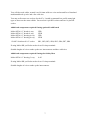
Oakley Sound Systems
5U Oakley Modular Series
VCO Controller
1U wide oscillator master module
Builder's Guide
V1.0.3
Tony Allgood
Oakley Sound Systems
CARLISLE
United Kingdom
Introduction
This is the Project Builder's Guide for the issue 1 VCO Controller 5U module from Oakley
Sound.
This document contains a basic introduction to the board, a full parts list for the components
needed to populate the board, interconnections and some basic testing methods.
For the User Manual, which contains an overview of the operation of the unit, advice on
connecting the unit and calibration procedures, please visit the main project webpage at:
http://www.oakleysound.com/cv-cont.htm
For general information regarding where to get parts and suggested part numbers please see
our useful Parts Guide at the project webpage or http://www.oakleysound.com/parts.pdf.
For general information on how to build our modules, including circuit board population,
mounting front panel components and making up board interconnects please see our generic
Construction Guide at the project webpage or http://www.oakleysound.com/construct.pdf.
This is an early version of the documentation. If you do find any errors, even silly little ones,
please do let me know either directly by e-mail or via the Forum or mailing list.
2
The VCO Controller PCB
This is the prototype unit with natural finish Schaeffer panel. Note the use of the Sock8 board to mount the
jack sockets. Two pot brackets are used to hold the PCB firmly to the front panel. The top pot does not have a
bracket since this would add extra height to the board and foul the MOTM mounting rails.
I have provided space for the three main control pots on the PCB. If you use the specified
16mm Alpha pots and matching brackets, the PCB can be held firmly to the panel without any
additional mounting procedures. The pot spacing is 1.625” and is the same as the vertical
spacing on the MOTM modular synthesiser and most of our other modules.
The design requires plus and minus 15V supplies. The power supply should be adequately
regulated. The current consumption is about 20mA for each rail. Power is routed onto the
PCB by a four way 0.156” MTA156 type connector or the special five way Synthesizers.com
MTA100 header. You could, of course, wire up the board by soldering on wires directly. The
four pins are +15V, ground, earth/panel ground, -15V. The earth/panel connection allows you
to connect the metal front panel to the power supply’s ground without it sharing the modules’
ground line. More about this later.
The PCB has four mounting holes for M3 bolts, one near each corner. These are not required
if you are using the two 16mm pot brackets.
The board size is 107mm (high) x 110mm (deep).
The board has been laid out to accept connection to our Sock8 socket board. This small board
speeds up the wiring of the eight sockets and reduces the chances of mistakes.
3
Components
For general information regarding where to get parts and suggested part numbers please see
our useful Parts Guide at the project webpage or http://www.oakleysound.com/parts.pdf.
Some special considerations for this project
The op-amps used in this project fall into two distinct categories, low offset voltage bipolar
and low input current FET types.
U2, 3 and 4 should be high quality low offset low drift op-amps such as the OPA2277 or
LT1013. These op-amps are used in the KCV pathway and should not contribute significantly
to any errors.
U1 and U7 should be FET types with low input bias current. The old stalwart the TL072 is
perfectly good enough for this, although you could use the LF412. U8 could be any op-amp
really, but the TL072 is cheap and good enough for this application.
You will also need two single pole double throw switches. These are sometimes called SPDT
or 1PCO (one pole changeover). They should be ON-OFF-ON types. This type of switch has
one contact with a wiper that can move between two outer contacts and have a middle
position that is touching neither outer contact. These switches have three solder tags and look
identical to the more common ON-ON type.
Watch out for sizes, there are many different types of toggle switches and some of them can
be very big and will clash with the PCB if using the suggested panel design. I use miniature flat
toggle types made by Apem and sold by Farnell.
There are several 0.1% tolerance resistors used in this project. I strongly recommend that you
use these and not 1% types in those locations. Failure to comply with this will mean that the
octave switching between KCV1 and KCV2 will probably not track each other.
The sockets may be fitted either directly to the panel and wired to the board using fly wires, or
you can use our Sock8 socket board. This is available from us and facilitates easy connection
from the sockets to the main board. If you are using the Sock8 board then it is recommended
that you use 0.1” Molex KK or MTA100 headers and housings to interconnect between the
two boards.
4
Parts List
For general information regarding where to get parts and suggested part numbers please see
our useful Parts Guide at the project webpage or http://www.oakleysound.com/parts.pdf.
The components are grouped into values, the order of the component names is of no particular
consequence.
A quick note on European part descriptions. R is shorthand for ohm. K is shorthand for kiloohm. R is shorthand for ohm. So 22R is 22 ohm, 1K5 is 1,500 ohms or 1.5 kilohms. For
capacitors: 1uF = one microfarad = 1000nF = one thousand nanofarad.
To prevent loss of the small ‘.’ as the decimal point, a convention of inserting the unit in its
place is used. eg. 4R7 is a 4.7 ohm, 4K7 is a 4700 ohm resistor, 6n8 is a 6.8 nF capacitor.
Resistors
All resistors should be 0.25W 1% metal film (MF) types unless stated.
Some resistors are 'precision' 0.1% types and are marked accordingly. These should not be
substituted with 1% MF.
75R
330R
390R
1K
2K2
4K7
6K8
8K2
10K
15K
19K6, 0.1%
20K, 0.1%
22K
39K
47K
51K
62K
82K
100K
100K, 0.1%
220K
330K
390K
470K
1M
3M3
R7, R12, R1
R50, R53
R35, R38
R51, R39, R43, R37
R27, R23, R52
R30
R29
R41
R15, R3, R2, R31, R19, R10
R47, R56, R45
R14, R8
R13, R17, R16, R9
R49
R20
R48, R26, R25
R21, R22
R36, R42
R46
R18, R28, R32, R24
R11, R6
R40, R34
R44
R54, R33
R5
R4
R55
5
Capacitors
33pF low-K or C0G ceramic
100pF low-K or C0G ceramic
22nF, 63V polyester film
100nF, 63V polyester film
100nF multilayer axial ceramic
2.2uF, 63V electrolytic
C3, C2, C18
C17, C12
C11, C10
C1
C14, C13, C7, C15, C8, C16, C4, C6, C5, C9
C20, C19
Discrete Semiconductors
BC560 PNP transistor
1N4148 silicon signal diode
Q3
D1, D2
Integrated Circuits
LM336Z-5.0 5V reference
LM13700 Dual OTA
LT1013CP
TL072
U5
U6
U2, U3, U4
U7, U1, U8
Trimmers
22K horizontal
100K horizontal
10K cermet multiturn
1K cermet multiturn
SHAPE
SYM, OFFSET
-OCT, +OCT
SCL1, SCL2
Potentiometers
50K linear Alpha 16mm
50K log Alpha 16mm
CV2/LFOMD, CV1/LFO
LFO_RATE
Two pot brackets are also required. LFO_RATE has no bracket.
Miscellaneous
Leaded Ferrite beads
SPDT on-off-on switch
Molex or MTA 4 way header
MTA100 6-way header
L1, L2
OCTAVE1, OCTAVE 2
PSU – Oakley/MOTM power supply
PWR – Synthesizers.com power supply
Molex/MTA 0.1” header 6-way
Molex/MTA 0.1” header 8-way
Molex/MTA 0.1” housing 6-way
Molex/MTA 0.1” housing 8-way
UPR – for connecting to sockets
LWR – for connecting to sockets
UPR – for connecting to sockets
LWR – for connecting to sockets
1/4” sockets
Eight off mounted either on the Sock8 board or on panel
6
You will also need solder, around 1m of 0.9mm solid core wire and around 2m of insulated
multistrand hook up wire and a few cable ties.
You may well want to use sockets for the ICs. I would recommend low profile turned pin
types as these are the most reliable. You need six 8-pin DIL sockets and one 16-pin DIL
socket.
Additional components required if using optional Sock8 board
Molex/MTA 0.1” header 6-way
Molex/MTA 0.1” header 8-way
Molex/MTA 0.1” housing 6-way
Molex/MTA 0.1” housing 8-way
UPR
LWR
UPR
LWR
112APC Switchcraft 1/4” socket
SK1, SK2, SK3, SK4, SK5, SK6, SK7, SK8
If using Molex KK you'll also need at least 28 crimp terminals.
Suitable lengths of wire to make up the two interconnects and three cable ties.
Additional components required if using the Oakley Buss
Molex/MTA 0.1” housing 3-way
8 off
If using Molex KK you'll also need at least 12 crimp terminals.
Suitable lengths of wire to make up the interconnects.
7
Connections
Power connections – MOTM and Oakley
The PSU power socket is 0.156” Molex/MTA 4-way header. Friction lock types are
recommended. This system is compatible with MOTM systems.
Power
Pin number
+15V
Module GND
Earth/PAN
-15V
1
2
3
4
Pin 1 on the LWR header has been provided to allow the ground tags of the jack sockets to be
connected to the powers supply ground without using the module’s 0V supply. Earth loops
cannot occur through patch leads this way, although screening is maintained. Of course, this
can only work if all your modules follow this principle.
Power connections – Synthesizers.com
The PWR power socket is to be fitted if you are using the module with a Synthesizers.com
system. In this case you should not fit the PSU header. The PWR header is a six way 0.1”
MTA, but with the pin that is in location 2 removed. In this way location 3 is actually pin 2 on
my schematic, location 4 is actually pin 5 and so on.
Power
Location number
Schematic Pin number
+15V
Missing Pin
+5V
Module GND
-15V
Not connected
1
2
3
4
5
6
1
2
3
4
5
+5V is not used on this module, so location 3 (pin 2) is not actually connected to anything on
the PCB.
If fitting the PWR header, you will also need to link out LK. This connects the panel ground
with the module ground. Simply solder a solid wire hoop to join the two pads of LK together.
Using the Sock8 board
This is the simplest way of connecting all the sockets to the main board. The Sock8 board
should be populated in the way described in our construction guide found on the project
webpage. There are only two headers, UPR (for upper) which is six way, and LWR (for
lower) which is eight way. Both headers are fitted to the bottom side of the board.
8
You need to make up two interconnects. The six way one should be made so that it is 90mm
long. The eight way should be made to be 140mm.
The prototype unit showing the detail of the board to board interconnects. Here I have used the Molex KK
0.1” system.
Module to Module Interconnects using the Oakley Buss
The standard build of the VCO Controller makes use of normalised connections to the other
modules in your modular synthesiser. Some further details of these are covered in the User
Manual.
The Oakley Buss conforms to a simple three way 0.1” Molex KK header, although you could
use a MTA100 header instead.
Pin 1 is keyboard control voltage KCV at a sensitivity of 1.000V/octave
Pin 2 is not normally used and is taken to ground on the Dizzy board.
Pin 3 is gate where a active note generates +5V, and an inactive note is 0V.
The VCO Controller does not use the gate signal but the two headers marked BUSS1 and
BUSS2 are connected so that gate and KCV signals are passed through.
9
Each Oakley Buss header on the board is therefore a three way device, but note that not all
three wires need to be connected to make it work properly.
CV1 is the header that sends KCV1 to your first VCO, or your bank of VCOs that you want
to control with the top octave switch. The Oakley VCO features a three way header on the
socket board. Simply connect the CV1 header to the this header and the VCO Controller will
now connect to the VCO. Only pin 1 need to be connected though. There is no need to wire in
all three wires to each housing.
If your VCOs do not have an Oakley Buss fitted, ie. Older issue 1, 2 and 3 boards, then you
need to make what I call a CV tail. You may have already done this if you used the Oakley
Buss on the Dizzy. If not making a tail is easy. Simply solder a suitably long wire onto the NC
lug of the 1V/octave input socket of the VCO. Attach it to a three way Molex or MTA
housing at location pin 1. If your VCO module has the NC connected to ground then remove
this before soldering on your tail.
CV2 is the header that sends KCV2 to your second VCO or your bank of VCOs that you
want to control with the bottom octave switch. Connect this as you have done with the CV1
header.
The Oakley midiDAC-3 already has a Oakley Buss header fitted. Simply make up a
interconnect that joins the midiDAC with the VCO Controller at BUSS1. You only need two
wires in your interconnect, there is no need to join the two pin 2s together, as we only want
KCV and gate to go to the VCO Controller. If you have an older issue 2 or issue 1 midiDAC
you will have to make some tails from the midiDAC's output sockets if you want
normalisation. You can, of course, simply use a patch lead to connect the VCO Controller's
KEY-CV socket to the midiDAC's KEY-CV socket.
BUSS2 can be connected to your modular's Dizzy board via another interconnect. Again use a
two wire interconnect as you probably want both KCV and gate to be present on your Dizzy.
Alternatively, if the Dizzy is already carrying KCV and gate from the midiDAC you may
simply use a single wired interconnect (pin 1 to pin1) to take KCV to the VCO Controller
from the Dizzy. You need not use BUSS2 in this case. The only issue with this is that KCV
has had to go through two sets of interconnects between the midiDAC and the VCO
Controller. The KCV signal is prone to some interference from noise and poor contacts. It is
therefore best to minimise the amount of interconnects it does have to travel through. Wiring
the midiDAC direct to the VCO Controller does minimise the risk somewhat particularly as it
is expected that the VCO Controller is situated next to the midiDAC.
Wiring the sockets without using a Sock8
The Sock8 was specifically designed to be used with the standard front panel layout which in
turn relies heavily on the use of the internal Oakley Buss. However, you may wish to utilise
different input and output combinations and hand wiring them to the main board may therefore
be more suitable.
Page 2 of the schematics show the full input and output sections of the module. There are six
0.1” headers on the board. Pin 1 is the square pad.
10
BUSS1
Pin 1 goes to pin 1 of BUSS2 and to pin 5 of UPR
Pin 2 goes to pin 2 of BUSS2
Pin 3 goes to pin 3 of BUSS3
CV1
Pin 1 CV1 output to VCO1 - the KCV output controlled by the top octave switch
Pin 2 not connected
Pin 3 not connected
CV2
Pin 1 CV2 output to VCO2 - the KCV output controlled by the bottom octave switch
Pin 2 not connected
Pin 3 not connected
UPR
Pin 1
Pin 2
Pin 3
Pin 4
Pin 5
Pin 6
VCA CV output
not connected
module ground
VCA CV input
Key CV from buss
Key CV input
- this is the low pass filtered output from VCA CV input
- joined on the PCB to pin 2 of the PSU/PWR connector
- this is the control voltage for the internal VCA
- joined on the PCB to pin 1 of BUSS1 and BUSS2
- the master KCV input to the module
NB Pins 3 and 5 go to the NC lugs of the VCA CV IN and KEY-CV sockets respectively.
LWR
Pin 1
Pin 2
Pin 3
Pin 4
Pin 5
Pin 6
Pin 7
Pin 8
Panel ground
Square wave out
VCA out
Sine wave out
Sine wave out 2
CV in
Sine wave out 2
VCA in
- connects to pin 3 of the PSU connector
- LFO output
- Output of internal VCA
- Output of sine shaper circuit
- Another output of sine shaper circuit.
- CV input – goes to the CV/LFO depth pot
- Copy of pin 5
- Audio/CV input to VCA
NB Pins 5 and 7 go to the NC lugs of the CV IN and VCA IN sockets respectively.
11
Testing, testing, 1, 2, 3...
Apply power to the unit making sure you are applying the power correctly. Check that no
device is running hot. Any sign of smoke or strange smells turn off the power immediately and
recheck the polarity of the power supply, and the direction of the ICs in their sockets and the
polarity of the electrolytic capacitors.
Now if you have not done so already it is time to plug the unit into your modular. You will
have several interconnects to fit before you can use the VCO Controller.
Set up a standard synthesiser patch of keyboard interface (midiDAC), two VCOs, a VCF,
VCA and an ADSR to gate the VCA. Set all the pots on the VCO Controller to their
minimum settings. Now play a few notes on your keyboard. You may notice that the pitch
goes slightly out of tune as you work your way up the keyboard. This is fine, you'll be
calibrating the scale later. Make sure that both octave switches change the pitch of the
connected VCOs. Again, you will not have a perfect octave shift but it should be fairly close.
Now turn the LFO/CV vibrato depth pot up. You should notice that both VCOs will start to
change pitch with the actions of the module's internal sine wave LFO. Check that the depth of
the effect gets greater the more the pot is turned up. Now change the LFO rate pot. Check
that the LFO frequency goes up as the pot is turned up. It should go to very slow to around
50Hz at its fastest.
Turn up the VCA Vibrato Depth. Hopefully, this should not do anything yet. If it does you
may have a problem with the VCA part of the circuitry.
Insert a patch lead from the ADSR or another LFO output into the CV IN socket. Check that
the VCO Controller's internal LFO is disconnected and that the inserted modulation source is
now controlling both VCOs instead. The LFO/CV Vibrato depth pot should still control the
depth of the modulation. Turn this pot to its lowest setting ready for the next test.
Remove the patch lead from the external modulation source. Connect the patch lead from the
aftertouch or modulation wheel CV output of the midi-CV convertor (or any other variable
CV source) to the VCA CV IN socket. Now turn up the VCA Vibrato Depth pot again. You
should find that as the applied CV goes up the internal LFO is once again modulating both
VCOs. The overall depth of the modulation is therefore controlled by both the depth pot and
the externally applied CV. With no aftertouch or mod wheel CV applied there should be no
LFO modulation heard.
Turn down the vibrato depth pot and connect another patch lead from the VCA CV OUT
socket to a cut off CV input on your filter. You should find that as the aftertouch or mod
wheel is applied then the filter's cut-off frequency rises. It should be smooth and not lumpy
like it normally is with CC information.
Check now that you have a rough sine wave output from the SINE OUT socket, and a square
wave output from the SQR OUT socket. You can modulate the cut-off frequency of the
connected VCF to hear the LFO's affects. The sine wave should cause the cut off frequency to
rise and fall smoothly, while the square wave will cause abrupt changes between two values.
12
Lastly, you need to check the operation of the VCA IN socket. Chances are that it will work
just fine because the CV control of LFO depth would not have worked otherwise, but let's
give it a go. Remove the audio output from your VCOs to the VCF. Put one of the VCO
outputs into the VCA IN of the VCO Controller module. Now connect the VCA OUT to the
input of the filter. You should find that the aftertouch or mod wheel now controls the volume
of the VCO being sent to the filter.
If all this happens, the chances are that you have a working module. Now before you start to
use it in your modular you will need to calibrate it. The full calibration procedure can be found
in the User Manual.
13
Final Comments
If you have any problems with the module, an excellent source of support is the Oakley Sound
Forum at Muffwiggler.com. Paul Darlow and I are on this group, as well as many other users
and builders of Oakley modules.
If you can't get your project to work, then Oakley Sound Systems are able to offer a 'get you
working' service. If you wish to take up this service please e-mail me, Tony Allgood, at my
contact e-mail address found on the website. I can service either fully populated PCBs or
whole modules. You will be charged for all postage costs, any parts used and my time at
25GBP per hour. Most faults can be found and fixed within one hour, and I normally return
modules within a week. The minimum charge is 25GBP plus return postage costs.
If you have a comment about this builder's guide, or have a found a mistake in it, then please
do let me know. But please do not contact me or Paul Darlow directly with questions about
sourcing components or general fault finding. Honestly, we would love to help but we do not
have the time to help everyone individually by e-mail.
Last but not least, can I say a big thank you to all of you who helped and inspired me. Thanks
especially to all those nice people on the Synth-diy and Analogue Heaven mailing lists and
those at Muffwiggler.com.
Tony Allgood at Oakley Sound
Cumbria, UK
© February 2010 – updated May 2013
No part of this document may be copied by whatever means without my permission.
14