1
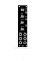
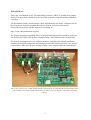
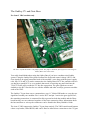
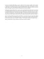
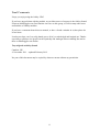
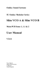
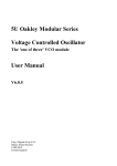
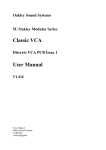
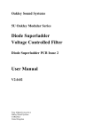
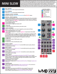
Oakley Sound Systems
5U Oakley Modular Series
Versatile Ramp Generator
VRG PCB issues 1 & 2
User Manual
V2.0.1
Tony Allgood B.Eng PGCE
Oakley Sound Systems
CARLISLE
United Kingdom
The suggested panel layout in MOTM format.
2
Introduction
This is the User Manual for the Versatile Ramp Generator (VRG) 5U module from Oakley
Sound. This document contains an overview of the operation of the unit and the calibration
procedure
For the Builder's Guide, which contains a basic introduction to the board, a full parts list for
the components needed to populate the board or boards, and a list of the various
interconnections, please visit the main project webpage at:
http://www.oakleysound.com/vrg.htm
For general information regarding where to get parts and suggested part numbers please see
our useful Parts Guide at the project webpage or http://www.oakleysound.com/parts.pdf.
For general information on how to build our modules, including circuit board population,
mounting front panel components and making up board interconnects please see our generic
Construction Guide at the project webpage or http://www.oakleysound.com/construct.pdf.
This is the prototype issue 1 VRG module behind a natural finish 1U wide MOTM format Schaeffer panel.
Issue 2 modules are almost identical but feature the Oakley Buss CV and gate connection on the main
board.
3
The Oakley Versatile Ramp Generator
The Oakley Versatile Ramp Generator (VRG) is a single width 5U high module that can
function as a voltage controlled variable symmetry oscillator, a traditional attack-decay
envelope generator, a one shot transient generator with patch programmed repeat, a voltage
controlled slew generator, a gate delay and an audio filter. The output slope can be either
linear or exponential.
The output signal will rise at a rate determined by the UP control and the up control voltage
input. The output signal will fall at a rate determined by the DOWN control and the down
control voltage input.
An additional output is available called NEG OUT. This output is a gate style signal that is 0V
when off and +5V when activated. The signal is called NEG OUT because it indicates that the
main output signal is has fallen below +0.6V and close to being a negative voltage.
A bi-colour LED gives visual indication of the module's main output signal level. When the
LED is red the output is a positive voltage, and when it is green the output is negative. The
brighter the LED lights the greater the output voltage.
The various operating modes of the instrument are determined by the three way mode switch
and use of the SLEW IN jack socket.
1. Slew generator
Inserting a jack into the SLEW IN socket activates the slew generator. The output of the
module now attempts to follow the input signal. However, the rise and fall times are
determined by the module's controls and the dedicated CV inputs. Fast moving inputs are thus
slewed at rates controlled by the VRG. You can use this mode for portamento effects, basic
filtering and creating attack-release envelope shapes.
The VRG can generate linear or exponential slopes. For basic filtering jobs you may find the
exponential mode more suitable. For portamento either linear or exponential will work.
Exponential pitch glides are often found in vintage monosynths while linear ones seem to be
more common for vintage polysynths. Linear ones essentially produce a glide time that is
dependant on the distance between the notes played. Exponential glides give the impression of
a constant glide time between notes – changing rapidly at first and then slowing as it reaches
its eventual target note.
In exponential mode there will be small error voltages present at the output of the VRG if the
up and down times are long. If the VRG is processing a keyboard's pitch control voltage
(KCV) these errors will lead to a change in the tuning of the controlled VCO. The amount of
error the VRG produces will be dependant on the up and down times set by the VRG's
controls or the controlling CVs. The longer the times the greater the error voltage. Great care
has been taken to ensure these error voltages are as low as they can be. The maximum error
voltage depends on the actual devices used in the VRG's manufacture. However, using good
4
quality parts should mean that the VRG produces low enough error voltages so that
exponential portamento is possible for all but the very longest of times. If you require
precision pitch control and very long portamento slides then use the VRG's linear mode. In
linear mode the VRG produces sub millivolt error voltages.
2. Variable symmetry low frequency oscillator
With no jack inserted into the slew in socket and the switch set to LFO, the VRG behaves as
an oscillator. The wave shape and frequency are controlled by the up and down controls and
their CV inputs.
The linear mode will produce a waveform that is similar to a standard triangle wave. The up
and down times can be varied so the VRG can produce sawtooth and ramp waveforms and
anything in between.
The exponential mode produces a similar waveform but the slopes are slightly curved. They
change faster initially and then slow as they reach the peak and troughs of the waveform.
Maximum frequency: 600Hz – linear
300Hz – exponential
Minimum frequency: 0.009Hz (one cycle per two minutes) – linear
0.003Hz (one cycle in over five minutes) – exponential.
Output level:
+5V to -5V.
3. Traditional attack-decay envelope generator
The gate input allows the VRG to be triggered as you would an ordinary envelope generator.
This makes it ideal for generating plucked sounds. Removing the gate while the attack phase is
ongoing will cause the output to fall back to zero at a rate determined by the decay controls.
Attack time:
0.5ms to 30s (linear)
0.75ms to 50s (exponential – measured 10% to 90% full scale)
Decay time:
0.5ms to 30s (linear)
2.2ms to 3 minutes (exponential – measured 90% to 10% full scale)
Output level:
0V to +5V
4. One shot transient generator
The gate input starts an attack-decay curve much like a traditional attack-decay envelope
generator. However, the attack phase will always complete even if the gate is removed before
it gets to the top of the cycle. This can create long lasting slowly moving output signals that
are triggered from just single short events.
5
Attack time:
0.5ms to 30s (linear)
0.75ms to 50s (exponential – measured 10% to 90% full scale)
Decay time:
0.5ms to 30s (linear)
2.2ms to 3 minutes (exponential – measured 90% to 10% full scale)
Output level:
0V to +5V
The one shot can be triggered to cycle endlessly up and down by connecting a patch lead from
the NEG OUT socket to the GATE socket.
The NEG OUT can be also used as a gate delay in the one shot mode.
Notes:
All the above figures were found by analysing the issue 2 prototype. It is likely that some of
these figures will be slightly different with each module made due to small tolerances in the
components used.
Issue 1 VRG modules used a different method of biasing the timing control circuitry. Issue 1
boards have marginally faster times and frequencies but reduced operating ranges.
6
The Oakley CV and Gate Buss
For Issue 2 VRG modules only
The three way BUSS header with jumper fitted. The jumper should be fitted if you are not using the
Oakley Buss interconnections.
You really should think about using the Oakley Buss if you have a medium sized Oakley
system. Using the Oakley Dizzy board it allows the 'keyboard control voltage' (KCV) and
Gate signals to be piped around the back of the modular’s case along with the power supply
rails. Any VCO and VCF can be connected to the Oakley Buss's KCV line, and this will save
you having to patch KCV to every module that needs it. Inserting any patch lead into the
1V/OCT socket will override the CV bus line connection. The gate signals are treated
similarly to the KCV line but for use with the ADSRs and other envelope generator modules
such as the VRG.
The Oakley CV/gate buss uses a common three way 0.1” Molex KK header to carry the two
signal lines around your modular. Pin 1 carries KCV and pin 3 carries the gate signal. Pin 2,
the remaining connection, is connected locally to ground on both the module and the Dizzy
board but they are not connected together via the buss connection. More information about
the buss and how to wire up the connectors can be found in the Dizzy Builder's Guide.
The issue 2 VRG supports the Oakley CV/gate buss natively. The VRG's main board features
a three way header, called BUSS, that can be fitted to allow direct connection to the CV/gate
7
buss on an installed Oakley Dizzy system or with our VCO Controller module. If not required,
a simple two way jumper, like those used on computer motherboards, can be fitted to connect
between pins 3 and 2. By fitting this jumper the GATE socket's signal lug is shorted to ground
when a jack plug is not inserted thus reducing pick up from stray signals.
Although the Oakley Buss header is a three way connector the actual interconnect you need to
use will normally have only one wire fitted. The Oakley VRG is connected only to pin 3 of the
Oakley Buss which is the connection carrying gate. This means you need to use only a single
wire that is terminated in a 3 way housing at either end. The last location of the housing, pin 3,
is the only one used with the other two locations being left empty and no other wires needed.
On no account should an interconnect with all three wires fitted be used to connect the Oakley
Buss to any module. The middle location, pin 2, is ground on the module and this should not
be connected to the Dizzy or midiDAC modules. Connecting the ground of a module to the
Dizzy ground in this way may introduce earth loops and other problems.
8
Power supply requirements
The design requires plus and minus 15V supplies. The power supply should be adequately
regulated. The current consumption with no output signal is about +44mA for the +15V rail
and -37mA for the -15V rail. This will increase by a further 6mA when the output signal is
high. Power is routed onto the PCB by a four way 0.156” MTA156 type connector or the
special five way Synthesizers.com MTA100 header.
Power connections – MOTM and Oakley
The PSU power socket is 0.156” MTA 4-way header. This system is compatible with MOTM.
Power
Pin number
+15V
Module GND
Earth/PAN
-15V
1
2
3
4
The earth/pan connection has been provided to allow the ground tags of the jack sockets to be
connected to the powers supply ground without using the module’s 0V supply. Earth loops
cannot occur through patch leads this way, although screening is maintained. Of course, this
can only work if all your modules follow this principle.
Power connections – Synthesizers.com
The PWR power socket is to be fitted if you are using the module with a Synthesizers.com
system. In this case the PSU header is not fitted. The PWR header is a six way 0.1” MTA, but
with the pin that is in location 2 removed. In this way location 3 is actually pin 2 on my
schematic, location 4 is actually pin 3 and so on.
Power
Location number
Schematic Pin number
+15V
Missing Pin
+5V
Module GND
-15V
Not connected
1
2
3
4
5
6
1
2
3
4
5
+5V is not used on this module, so location 3 (pin 2) is not actually connected to anything on
the PCB.
If the PSU header is fitted then pins 2 and 3 of PWR are linked together. This connects the
panel ground with the module ground.
9
Calibration
Although you can use a simple fine bladed screwdriver for this adjusting the single trimmer
you should really use a proper trimmer tool. Vishay, Bourns and others make trimmer
adjusters for less than a pound.
You should make sure your modular has been powered up for at least ten minutes prior to
calibration. Also, it is a good idea to have the room temperature close to what it would
normally be when playing your modular.
Connect up your modular so that you can hear the output of a VCO. Connect the VCO to
your keyboard or other controller so you can control the pitch. Now play a high A on your
keyboard. This note should normally produce a note of 880Hz. Tune your VCO, with the
VCO's fine frequency control so that it produces as close to 880.0Hz as you can get it.
Now unplug the keyboard controller's output cable from the VCO's 1V/octave input and route
that instead to the VRG's slew input. Connect the VRG's output to the VCO's 1V/octave
input. Set the VRG's UP and DOWN controls to their minimum values, ie. fast, and the shape
switch to LIN. Now play the same note again and adjust the GAIN trimmer to give you
exactly 880.0Hz.
Check a few other notes up and down the keyboard to verify that the VRG hasn't altered the
scaling of the VCO.
10
Final Comments
I hope you enjoy using the Oakley VRG.
If you have any problems with the module, an excellent source of support is the Oakley Sound
Forum at Muffwiggler.com. Paul Darlow and I are on this group, as well as many other users
and builders of Oakley modules.
If you have a comment about this user manual, or have a found a mistake in it, then please do
let me know.
Last but not least, can I say a big thank you to all of you who helped and inspired me. Thanks
especially to all those nice people on the Synth-diy and Analogue Heaven mailing lists and to
those at Muffwiggler.com forum.
Tony Allgood at Oakley Sound
Cumbria, UK
© November 2011 – updated February 2012
No part of this document may be copied by whatever means without my permission.
11