1
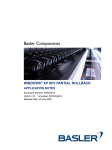
User Manual
NiMH/NiCd Charger
452115-N, 452215-N,
452116-N, 452415-N Series
READ THESE INSTRUCTIONS BEFORE USING THE CHARGER
This battery charger is only designed for indoor use and should not
come into contact with water or dust. In order to avoid overheating,
the charger should not be covered when it is in use.
If the charger is marked with a symbol with two drops of water and
“IP67”, the unit is filled with molding material and is waterproof,
but must not be immersed in water over long periods of time.
IP67
The charger is turned on by connecting it to the mains socket.
Disconnecting it from the mains socket turns the charger off.
If the charger is equipped with a mains cord, verify that the cord
has not been damaged. If the cord is damaged, the charger must
not be used.
The mains socket should be easily accessible. If an operational
error occurs, the plug should be immediately removed from
the socket.
In the event that the charger is labeled “EN60601-1”, then it satisfies
the requirements of electromedical equipment and can be used in
hospital environments, etc. The charger must not be used in the
vicinity of flammable anesthesia gases.
If the charger is marked with this symbol it is double insulated
(class II).
The charger contains dangerous voltages and the cover should
not be removed. All service or maintenance work should be carried
out by qualified personnel who can get assistance by contacting
the manufacturer’s agent.
If the product has plastic casing, avoid it coming into contact with
oils, greases, etc., as most types of plastic can be broken down
by chemicals and solvents.
Technical specification: See product labeling.
1
CHARGER FUNCTIONALITY
This charger is a fast charger for NiCd/NiMH batteries. The standard
version utilizes a method called -dV detection for charge termination
when the batteries are fully charged. This method is based on the fact
that the voltage drops over the NiCd/NiMH cells when batteries are fully
charged. This voltage drop is detected when the voltage has dropped
a certain percentage from the highest value. If this drop does not occur,
the charger has a safety timer which will terminate charging after a given
time period to avoid overcharging the batteries. A few cells may have
a voltage drop in the first part of the charge cycle. This is especially true
for battery cells which have been idle for a longer period of time.
Because of this, it is built into the charger a start-timer which prevents
-dV detection the first minutes of the charge cycle.
As the charger is programmable (by the factory), it is possible that the
standard parameters, which this user manual is based on, have been
changed. See separate user manual or contact supplier for additional
information.
CAUTION
• When charging separate battery cells, avoid charging cells with
different rest-capacities at the same time.
• Do not charge batteries at too high or too low temperatures. See technical specification for the batteries for allowed temperature ranges.
• Make sure the batteries can handle the charge current. Contact battery
manufacturer for details.
• Make sure the batteries are connected with correct polarity.
• Never change more battery cells than what the charger is designed for.
2
HOW TO USE THE CHARGER
The Charger is started by connecting the battery pack to the charger.
The LED will be orange before the fast charge starts and the LED
changes to red. When the batteries are fully charged and the
voltage drops because of the –dV signal from the batteries, the
charger will go into a top-off charge mode before it goes over to trickle
charge mode. During top-off charge the LED will be green with short
intermittent orange light. When the top-off charge is completed, the
charger will go into trickle charge mode and the LED will be green.
The charge current is now reduced to a safe level, which allows the
charger to stay connected to the NiCd batteries without damaging
the batteries. NiMH batteries are not as well suited for trickle charge,
and some battery manufacturers recommend that trickle charge does
not exceed 24 hours.
If the safety timer disconnects before –dV, the top off charge will not
be engaged. The charger will then go directly to trickle charge mode
and the LED will be green. If the battery voltage is far below normal,
the charger will cut off the fast charge current and go to trickle charge
mode. The LED will then indicate ‘error’ by flickering green and red
light. If the mains are turned off, the charger will reset and start a new
charge cycle if the mains are turned on again.
If new batteries are to be connected, the charger must idle for approximately 15 seconds to make sure all parameters in the microprocessor
have been reset. The LED changing to yellow light shows this and a
new charge cycle can begin.
3
SAFETY
The embedded charge program has numerous features for safe charge:
• The charger is made with a –dV level which will adapt to the number
of cells and will be equally sensitive across all cells.
• The safety timer will protect the batteries if the –dV signal fails
to appear. It is normal to have a safety timer that is higher than
maximum charge time.
• Some battery cells may have a voltage drop in the first part of the
charge cycle. Because of this, a start timer that prevents –dV detection
during the first minutes of the charger cycle is built into the charger.
• The charger has been programmed to disregard large voltage
fluctuations due to connection of external loads. Such false –dV
signals will be detected by the software and disregarded.
• Top-off charge after –dV secures full battery capacity prior to trickle
charge. The charger may also be supplied without top-off charge.
• The charger is protected against reverse polarity by an automatically
resettable polyswitch fuse on output.
• The unit is constructed for the lowest possible leakage current from
the battery with mains disconnected (<1mA). It is still recommended
that the batteries be disconnected when the mains are not connected.
• On request, the charger is supplied with battery temperature
monitoring. A built-in temperature charge control (+dT/dt) secures
optimal charge with a built-in NTC resistor in the battery pack.
• Other functions such as 0dV detection and timer only charge is
available upon request. Most charge parameters may be altered
using an external programming tool. Contact manufacturer for details.
4
CHARGE CYCLE AND LED INDICATIONS
LED
MODE
Orange
Battery not connected
Orange
Battery initialization & analysis
Red
Fast charge
Green with intermittent orange flash
Top-off charge
Green
Trickle charge
Alternating red-green
Error
With mains connected the LED will be orange the first 5-7 seconds,
and be orange when the initialization and analysis starts. If a battery
is connected, the actual charging will start a few seconds later when
the LED changes to red.
After the start timer period has run out (the first few minutes of the
charge cycle when the –dV is undetected), the LED will be green in
approximately 4 seconds. This is only a signaling for testing and service.
When –dV has been detected, the start of the top-off charge is indicated
with a green LED with intermittent orange flashes as described under the
“how to use the charger” section. The LED is green during trickle charge.
5
TEMPERATURE CONTROL (OPTIONAL FEATURE)
If the charger is being used with temperature sensor (NTC - resistor
in the battery) it is possible to add control to the battery charging
process. If the battery temperature is too low (<0ºC) at the start of the
charge cycle, the charger will charge with trickle charge current until
the temperature level is safe. This is indicated by intermittent red
flashes while the LED is green. The same will take place if the battery
temperature exceeds 40ºC. The current will then remain low until the
temperature is at a level where fast charge can start.
If the temperature is too high (>60ºC), the LED will show “error” by
flashing red and green lights intermittently. By using the temperature
increase control (+dT/dt), the charger will switch to top-off charge and
later to trickle charge the same way as charging with –dV control.
NOTE: The charger may be programmed with other temperature
parameters. See separate user manual or contact supplier
for additional information.
ZERO dV FEATURE
If zero dV has been activated, the charger will stop the fast charge
when the voltage has not increased the last 5 minutes. This feature
may be the only sensor, or it may be used in combination with
–dV and/or +dT/dt.
OUTPUT CONNECTOR SPECIFICATIONS
If charger is equipped with a 2.5 x 5.5 x 9.5 mm barrel plug, the
center position is positive.
If the charger is equipped with a 3 pin
DIN plug, please refer to illustration for
proper polarity.
Provided DIN plug (Lumber model #XS32)
mates with Lumberg model #XK32.
THERM.
POS.
NEG.
6
42205�
305 Commerce Drive, #300 • Exton, PA 19341
voice: 610.280.7630 • 800.771.7139
fax: 610.280.7685 • web: www.cell-con.com
Doc. # 410060-0050 04/16/08