1
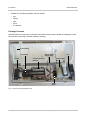
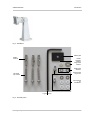
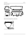
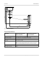
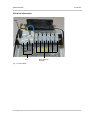
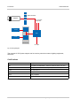
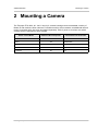
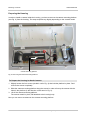
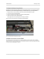
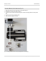
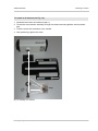
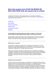
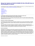
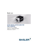
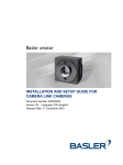
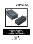
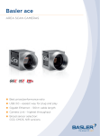
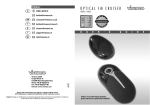
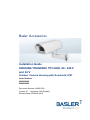
T F A DR Basler Accessories Installation Guide HOUSING TRANSPAC TPH 4000, 90 - 240 V and 24 V Outdoor Camera Housing with Sunshield, IP67 Order Numbers 2000032062 2000032063 Document Number: AW001299 Version: 01 Language: 000 (English) Release Date: 26 March 2014 Contacting Basler Support Worldwide Europe and the Middle East: Basler AG An der Strusbek 60 - 62 22926 Ahrensburg Germany Phone: +49 4102 463 515 Fax: +49 4102 463 599 Email: [email protected] The Americas: Basler, Inc. 855 Springdale Drive, Suite 203 Exton, PA 19341 U.S.A. Phone: +1 610 280 0171 Fax: +1 610 280 7608 Email: [email protected] Asia: Basler Asia Pte. Ltd 35 Marsiling Industrial Estate Road 3 # 05 - 06 Singapore 739257 Phone: +65 6367 1355 Fax: +65 6367 1255 Email: [email protected] www.baslerweb.com All material in this publication is subject to change without notice and is copyright Basler AG. AW00129901000 Introduction 1 Introduction NOTICE When using this housing in aggressive environments (e.g. where it is exposed to high humidity, salt water, or other corrosive elements), corrosion of the housing and/or camera can occur. To prevent this, seal all external stainless steel screws and fittings with a silicone grease compound. This will help to extend the lifespan of the housing and the camera. This is especially important for the wall mount. WARNING Incorrect electrical connections can damage the camera and lead to injuries when using the housing and camera. 1. Disconnect the camera from the main power supply before opening the housing. 2. Electrical connections should only be made by a qualified electrician. Purpose of this Document This document is designed to give an overview over the technical specifications of the Transpac TPH 4000, 90 - 240 V and 24 V, housings. It will also explain how to install a camera inside a housing of this series. This document should be used in conjunction with the respective Basler camera user’s manual. Key Features of the Camera Housing Die-cast aluminum housing, ivory-colored powder coating Fully cable-managed wall mount Suitable for indoor/outdoor installation Adjustable camera mounting platform for IP and machine vision cameras by Basler Internal heater for defogging Internal fan for temperature management IP67 cable glands Internal power supply unit with spare terminal and fuse block Weight: 4 kg Housing Transpac TPH 4000, 90 - 240 V and 24 V 1 Introduction AW00129901000 Suitable for the following Basler camera models: ace aviator pilot scout IP cameras Package Contents Included with the housing are a wall mount as well as various parts needed for installing the wall mount and for mounting a camera inside the housing. Front window Thermostat Heater Fan Internal power supply cable Power supply unit Camera mounting platform Cable gland Fig. 1: Camera Housing (Internal View) 2 Housing Transpac TPH 4000, 90 - 240 V and 24 V AW00129901000 Introduction Fig. 2: Wall Mount Plastic pad Plastic anchors Plastic shoulder washer Large steel washer Small steel washers Socket head cap screw Hex head cap screws Not required for installation L-type hex key Fig. 3: Assembly Parts Housing Transpac TPH 4000, 90 - 240 V and 24 V 3 Introduction AW00129901000 Items needed for installing the wall mount: 3 plastic anchors 3 stainless steel hex head cap screws 1 L-type hex key Items needed for mounting a camera inside the housing: 1 steel socket head cap screw, 1/4" x 1/2" 1 plastic pad 1 plastic shoulder washer 1 large steel washer 2 small steel washers 1 L-type hex key Note that all other parts included in the package are not needed for standard installations. 4 Housing Transpac TPH 4000, 90 - 240 V and 24 V AW00129901000 Introduction Dimensions (in mm) 130 58 89 405 126 370 150 80 150 50 Fig. 4: Dimensions Housing Maximum dimensions (external): 405 (L) x 150 (W) x 150 (H) 94.95 69.00 82.80 12.98 Maximum camera mounting space: 260 (L) x 90 (W) x 70 (H) Fig. 5: Dimensions Wall Mount Base Housing Transpac TPH 4000, 90 - 240 V and 24 V 5 AW00129901000 95 105 50 Introduction 15 190 227 Fig. 6: Dimensions Wall Mount Technical Specifications Specification Camera Housing with Order Number 2000032062 Camera Housing with Order Number 2000032063 External Power Supply 90 - 240 VAC Input Power Supply 24 VAC Input Power Supply Internal Power Output 3 x 12 VDC, max. 3.5 A (including heater and fan) Heater Control 18 °C (On) / 28 °C (Off) Fan Control 35 °C (On) / 25 °C (Off) Operating Temperature -20 °C to 50 °C Note: Check the operating temperature of the camera you are going to use as its operating temperature may differ from that of the housing. Protection Level IP67 Temper Glass Thickness 4 mm Table 1: Specifications 6 Housing Transpac TPH 4000, 90 - 240 V and 24 V AW00129901000 Introduction Electrical Information Fuse PE (Protected Earth) AC in Spare electrical terminals Fig. 7: Terminal Block Housing Transpac TPH 4000, 90 - 240 V and 24 V 7 Introduction AW00129901000 Spare terminals Camera 3 x 12 VDC open wire Heater PSU Fan Thermostat AC input Fig. 8: Wiring Diagram The unused 12 VDC power outputs can be used to power lens motors, lighting equipment, sirens etc. Certifications CE Compliant with EN 55022:2010 Class B LVD Compliant with EN 60950-1:2006+A11:2009+A1:2010+A12:2011 FCC Compliant with FCC Part 15:Subpart B (10-1-10 Edition) Class B CISPR 22:2008 Class B IP67 Compliant with IEC 60529 RoHS Fully compliant SVCH Fully compliant Table 2: Certifications 8 Housing Transpac TPH 4000, 90 - 240 V and 24 V AW00129901000 Mounting a Camera 2 Mounting a Camera The Transpac TPH 4000, 90 - 240 V and 24 V, camera housings can accommodate a variety of Basler IP and machine vision cameras. For Basler machine vision cameras, an additional camera mount is required which has to be purchased separately. Table 3 gives an overview over which camera mount is required for which camera. Basler Camera Model Additional Mount Required? Camera Mount Order Number ace Yes 2000029679 aviator Yes 2000015984 pilot Yes 2000023896 scout Yes 2000023894 IP Camera No n/a Table 3: Camera-specific Mounting Information Housing Transpac TPH 4000, 90 - 240 V and 24 V 9 Mounting a Camera AW00129901000 Preparing the Housing In order to install a camera inside the housing, you have to remove the camera mounting platform (see Fig. 9) from the housing. The steps required vary slightly depending on the camera model. Camera mounting platform Fig. 9: Removing the Camera Mounting Platform To Prepare the Housing for Small Cameras: 1. Slightly loosen the four screws (circled in red in Fig. 9) that hold the platform in place. Don’t remove the screws completely. 2. Slide the camera mounting platform along the screws in order to line up the screws with the holes in the platform (in the direction of the arrow in Fig. 9). 3. Lift off the camera mounting platform. The screws remain in place, still attached to the housing body. Now you can mount a camera on the camera mounting platform. 10 Housing Transpac TPH 4000, 90 - 240 V and 24 V AW00129901000 Mounting a Camera To Prepare the Housing for Large Cameras: By default, the camera mounting platform sits on four spacers (see Fig. 10). You have to remove these before you can install a large camera (e.g. a Basler aviator) on the mounting platform. 1. Remove the four screws (circled in red in Fig. 9) that hold the platform in place. 2. Lift off the camera mounting platform. 3. Remove the spacers that support the camera mounting platform. 4. Return the screws to their original position. Don’t tighten them fully. Screwing them in loosely is sufficient. Now you can mount a camera on the camera mounting platform. Spacers Fig. 10: Mounting Platform Supported by Spacers Installation Instructions by Camera Model The following figures demonstrate how to install the different camera models. When installing Basler cameras, it is recommended to use two small steel washers as well as the large steel washer in order to prevent damaging the camera. Housing Transpac TPH 4000, 90 - 240 V and 24 V 11 Mounting a Camera AW00129901000 To Install a Machine Vision Camera (see Fig. 11): 1. Attach the camera mount to the bottom of the camera (step 1). 2. Assemble the screws and washers (step 2). 3. Thread the screw-washer assembly through the camera mounting platform and the plastic pad. 4. Twist the screw into the camera mount. 5. After positioning, tighten the screw. Step 1 Step 2 Fig. 11: Installing a Machine Vision Camera (ace GigE Shown as an Example) 12 Housing Transpac TPH 4000, 90 - 240 V and 24 V AW00129901000 Mounting a Camera To Install an IP Camera (see Fig. 12): 1. Assemble the screws and washers (step 1). 2. Thread the screw-washer assembly through the camera mounting platform and the plastic pad. 3. Twist the screw into the bottom of the camera. 4. After positioning, tighten the screw. Step 1 Fig. 12: Installing an IP Camera Housing Transpac TPH 4000, 90 - 240 V and 24 V 13 Mounting a Camera 14 AW00129901000 Housing Transpac TPH 4000, 90 - 240 V and 24 V AW00129901000 Revision History Revision History Doc. ID Number Date Changes AW00129901000 26 Mar 2014 Initial release of this document. Housing Transpac TPH 4000, 90 - 240 V and 24 V 15 Revision History 16 AW00129901000 Housing Transpac TPH 4000, 90 - 240 V and 24 V