Download User manual EPH4BXP1PS
Transcript
Evco S.p.A.
c-pro 3 CLIMA sistema | User manual ver.1.0 | Code 115CP3CSE104
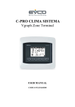
c-pro 3 CLIMA sistema
Zone Terminal
ENGLISH
USER MANUAL ver. 1.0
CODICE 115CP3CSE104
page 1 of 14
Evco S.p.A.
c-pro 3 CLIMA sistema | User manual ver.1.0 | Code 115CP3CSE104
Important
Important
Read this document thoroughly before installation and before use of the device and follow all recommendations; keep
this document with the device for future consultation.
The following symbols support reading of the document:
indicates a suggestion
indicates a warning.
The device must be disposed of in compliance with local Standards regarding the collection of electric and electronic
equipment.
page 2 of 14
Evco S.p.A.
c-pro 3 CLIMA sistema | User manual ver.1.0 | Code 115CP3CSE104
INDEX
1
2
3
USER INTERFACE ....................................................................................................................................4
1.1
Display and keyboard ......................................................................................................................4
1.2
Navigation .....................................................................................................................................4
1.3
Preselection page ............................................................................................................................5
1.4
System page ..................................................................................................................................6
1.5
Maintenance page ...........................................................................................................................6
1.6
Zone Page .....................................................................................................................................7
1.7
Functioning in “Manual” or “Time Period” mode ..................................................................................8
1.8
Set-point menu ............................................................................................................................ 10
1.9
Alarms......................................................................................................................................... 10
Installation ........................................................................................................................................... 11
2.1
Wall recessed in 506E box ............................................................................................................. 11
2.2
Wall-installation, on EVCO CPVW00 support ..................................................................................... 11
2.3
Panel installation .......................................................................................................................... 12
Electric connections ............................................................................................................................... 12
page 3 of 14
Evco S.p.A.
c-pro 3 CLIMA sistema | User manual ver.1.0 | Code 115CP3CSE104
1
USER INTERFACE
1.1
Display and keyboard
The user interface is composed of a membrane keyboard with 6 keys with one-colour graphical LCD (black with white
LED back-lighting), with 128 x 64 pixel, which confers the instrument with large information capacity joined with userfriendliness.
1.2
Navigation
There are 6 navigation and value editing keys present in the keyboard with the following meaning:
-
(UP and DOWN) are used to scroll the parameters inside the pages and to modify the value once in
modification mode.
-
(LEFT and RIGHT) used to scroll the pages of the main menu.
-
(ESC) used to go back to previous screens.
-
(ENTER) used to select the parameters to edit and to confirm the value once edited.
page 4 of 14
Evco S.p.A.
1.3
c-pro 3 CLIMA sistema | User manual ver.1.0 | Code 115CP3CSE104
Preselection page
In switch-on after the introductory welcome page, the zone terminal will show one of the following selection pages,
depending on the type of system in which the zone terminal has been installed:
Screen 1
Screen 2
Screen 3
Screen 1: direct access to the ZONE page.
If accessing directly to screen 1, pass directly to chapter 1.5 for the description of the functionalities.
Screen 2: Zone A / Zone B pre-selection page
If accessing screen 2, the user can control two different system zones, called Zone A and Zone B using just one
Vroom.
Taking the cursor over the desired zone and pressing the ENTER key, access the Zone selected.
Screen 3: Zone A / Zone B / System pre-selection page
If accessing screen 3, the User can use just one Vroom to control all of the different zones present in the system.
By taking the cursor over “Sistema” (System) and pressing ENTER, access the system page (screen 4, descried in
paragraph 1.4), where it will be possible to select which MCZN zone regulator (or MCCT thermal power plant regulator)
to access.
By taking the cursor over the desired zone (Zone A or Zone B) and pressing ENTER, enter the selected zone of the
selected MCZN regulator.
page 5 of 14
Evco S.p.A.
c-pro 3 CLIMA sistema | User manual ver.1.0 | Code 115CP3CSE104
1.4
System page
Screen 4
The “system page” (screen 4), as well as giving the possibility to navigate between the various zone regulators
present in the system, will supply some main information regarding the controlled system and on the status of the
zone regulators connected to it.
At the side of every zone regulator (indicated with ZN1, ZN2… ZN8) in fact one of the following codes will appear:
*
=
zone regulator not present,
?
=
zone regulator enabled but offline (contact service),
A
=
zone regulator enabled, on-line, in alarm status (contact service),
!
=
zone regulator present but disabled,
=
=
zone regulator enabled, on-line, with no
heating/cooling request coming from controlled zones.
+
=
zone regulator enabled, on-line, with
heating/cooling request coming from controlled zones.
1.5
Maintenance page
Whenever maintenance operations are in progress in the system, all Vroom displays installed will show the
maintenance page stated below:
During this display all setting/display procedures via Vroom are prohibited.
Once maintenance has bee completed, the zone terminal will automatically go back to the Pre-selection page
envisioned by installation.
page 6 of 14
Evco S.p.A.
1.6
c-pro 3 CLIMA sistema | User manual ver.1.0 | Code 115CP3CSE104
Zone Page
Date and time
Time period in progress
Zone temperature and humidity
Set-point of the time period in progress
External temperature
Name of the zone displayed
Alarm in progress (flashing)
Summer/Winter (mode in progress)
The “zone page” is the Vroom main screen, i.e. the standard display pages on which Vroom will stop during operator
inactivity periods.
This screen allows to display:
-
Name of the Zone displayed
-
Temperature and Humidity (if enabled) of the Zone displayed,
-
External temperature (if enabled),
-
Date and real time
-
Time period in progress for the Zone displayed
-
System work mode (summer/winter)
-
Presence of alarms blocking the system (see paragraph 1.8).
It also allows to modify:
-
Work set-point in progress.
Taking the cursor onto the “Set” label and pressing ENTER, sit will be possible to edit the set-point value in
progress using the UP and DOWN keys. Once the desired temperature has been set, press ENTER to confirm
the new value.
The work set-point modification is only temporary. On successive loading of the time period in progress, the
set-point value established of the relevant set-point menu will be loaded (paragraph 1.7)
By pressing ESC on the “Zone Page”, the zone terminal will go back to the pre-selection page configured for the
system (see paragraph 1.3).
page 7 of 14
Evco S.p.A.
1.7
c-pro 3 CLIMA sistema | User manual ver.1.0 | Code 115CP3CSE104
Functioning in “Manual” or “Time Period” mode
Manual Functioning Mode
Whenever management of the time periods is not enabled by the user, the system works in MANUAL mode (indicated
by MAN on the zone page).
By default the system loads the ECONOMY work set-point (both winter and summer), keeping the work set-point
unaltered through time. unless the user must change the manual set-point.
Functioning in Time Period mode
The c-pro 3 CLIMA sistema gives the final user the possibility to set a weekly automatic time periods system,
independently for each zone.
Enabling Time periods
To enable the weekly time periods system, it is necessary to go to the “Menu fasce orarie” (Time periods menu) from
the Zone Page using the LEFT or RIGHT keys and take the "Abilita" (Enable) parameter to YES.
Once the time periods management is enabled, the system automatically goes into the following state:
WINTER:
ANTI-FREEZE (with system standard safety value set by the system installer).
SUMMER:
OFF
page 8 of 14
Evco S.p.A.
c-pro 3 CLIMA sistema | User manual ver.1.0 | Code 115CP3CSE104
Setting Time Periods
By entering the "Set periods" menu it will be possible to enable the automatic switch-on of the system for every day of
the week and set up to 3 COMFORT periods defined with activation time and duration (parameters expressed in
hours).
In order to ease comprehension and setting, the next page gives a complete example of setting daily time periods.
Take the cursor onto the day selector of the week and press ENTER. Use the UP and DOWN keys to scroll to the day
desired to set the time periods (in this case MONDAY) and PRESS enter again.
After having selected the day of the week to be set, move the cursor onto the daily enabling box and press ENTER to
take the value to YES (whenever enabling is at NO, the system will go into the "rest" position, i.e. in OFF for the entire
day during the summer period and into ANTI-FREEZE during the winter period. Useful settings for the week-end in the
case of industrial installations such as offices, shops, etc…). To confirm press ENTER again.
By moving the cursor onto the following fields it will be possible to enable up to three daily time periods with
"Comfort" set-point in the following way:
“F1 Mode”:
“Ora” (Time):
No = period 1 with Economy set-point; Comfort = period 1 with Comfort set-point
Time of enabling of the relative time period (only has sense if set in Comfort mode)
“Durata” (Duration):
Duration of the Comfort time period enabled (only has sense if set in Comfort mode)
Once daily setting has ended, take the cursor onto the "Salva" (Save) box and press ENTER.
Use the UP key to move the field value from “NO” to “YES” and press ENTER to save the settings made.
Once saving has been completed, the "YES" label will automatically go back to the "NO" value.
EXAMPLE
With the settings inserted in the previous example screen, the following functioning is obtained.
Time
??:?? - 07:00
Economy
Time
07:00 - 09:00
Comfort
Time
09:00 - 12:00
Economy
Time
12:00 - 14:00
Comfort
Time
14:00 - 17:00
Economy
Time
17:00 - 22:00
Comfort
Time
22:00 - ??:??
Economy
(until
the
successive
morning 07:00).
page 9 of 14
Comfort
activation
time,
e.g.
Tuesday
Evco S.p.A.
1.8
c-pro 3 CLIMA sistema | User manual ver.1.0 | Code 115CP3CSE104
Set-point menu
The c-pro 3 CLIMA sistema gives the final user the possibility to set all weekly automatic time periods work set-points
independently for each zone in a simple and intuitive way via a unique user screen.
To set the work set-points of the time periods it is necessary to go to the "Menu setpoint” (Set-point menu) from the
Zone page using the LEFT or RIGHT navigation keys. The following screen will appear:
To set the set-point just position the cursor on the value to be edited and press ENTER.
Use the UP and DOWN keys to set the desired value and then confirm again using the ENTER key.
The set-points that can be set by the user are:
Economy set-point [W]:
Winter Economy period work set-point
Comfort set-point [W]:
Winter Comfort period work set-point
Economy set-point [S]:
Summer Economy period work set-point
Comfort set-point [S]:
Winter Comfort period work set-point
Humid. ECO [S+W]:
Economy time period work set-point (Summer + Winter, with regulation active only
in Summer mode)
Humid. COM [S+W]:
Comfort time period work set-point (Summer + Winter, with regulation active only
in Summer mode)
1.9
Alarms
Whenever during the display of the Zone Page Vroom shows the flashing ALARM icon, it means that one of the
following alarms blocking the system is in progress:
-
MCCT thermal power plant regulator off-line
-
Outlet line circulation pump block
-
Chiller/heat pump block
-
Boiler block
Call the after-sales service immediately to request system maintenance.
page 10 of 14
Evco S.p.A.
2
c-pro 3 CLIMA sistema | User manual ver.1.0 | Code 115CP3CSE104
Installation
There are three possibilities to assembling the Vroom graphical zone terminal.
2.1
Wall recessed in 506E box
2.2
Wall-installation, on EVCO CPVW00 support
page 11 of 14
Evco S.p.A.
c-pro 3 CLIMA sistema | User manual ver.1.0 | Code 115CP3CSE104
2.3
Panel installation
3
Electric connections
page 12 of 14
Evco S.p.A.
c-pro 3 CLIMA sistema | User manual ver.1.0 | Code 115CP3CSE104
c-pro 3 CLIMA sistema
User manual ver. 1.0
GL - 24 / 12
Code 115CP3CSE104
This document is exclusive property of EVCO. Reproduction and disclosure are prohibited without express authorisation
from EVCO.
EVCO is not liable for any features, technical data and possible errors stated in this document or deriving from use of
the same.
EVCO cannot be considered liable for damage caused by failure to comply with warnings given in this document.
EVCO reserves the right to make any changes without forewarning, without jeopardising the basic safety and
operating features.
page 13 of 14
Evco S.p.A.
c-pro 3 CLIMA sistema | User manual ver.1.0 | Code 115CP3CSE104
EVCO S.p.A.
Via Mezzaterra 6, 32036 Sedico Belluno ITALIA
Tel. 0437 / 84.22
Fax 0437 / 83.648
[email protected]
www.evco.it
page 14 of 14


