1
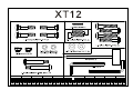
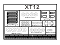
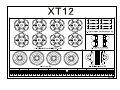
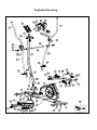
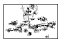
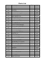
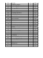
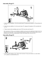
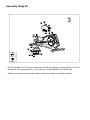
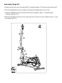
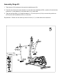
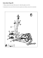
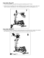
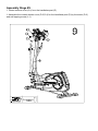
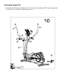
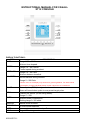
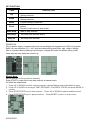
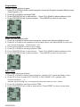
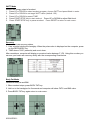
XT-12
USER MANUAL
Exploded drawing.
Parts List
Number
A, A-1
B
B-1
B-2
B-3
B-4
B-5
B-6
C
C-1
C-2
C-3
D
D-1
D-2
D-3
D-4
D-5
D-6
E-L
E-R
E-1
E-2
E-3
E-4
E-5
E-6
F
F-2
F-3
F-4
F-5
F-6
F-7
F-8
F-9
F-10
F-11
F-12
F-13
F-14
F-15
Description
Console & Screw
Front handlebar
Foam grip
Hand pulse
End cap for front handlebar
Screw M4x20L for hand pulse
Semicircle washer 1.5T for hand pulse
Wire for hand pulse
Upper handlebar (Left)
End cap for upper handlebar
Foam grip for upper handlebar
Upper handlebar (Right)
Handlebar post
Cable (upper) for handlebar post
Screw M5xP0.8x12L
Cover for console holder(Left)
Cover for console holder(Right)
Bushingφ38.1xφ17.12x15L
Axle for the handlebar post
Lower handlebar(Left)
Lower handlebar(Right)
Bushing φ38.1xφ17.12x15L
C type ringφ12
Flat washerφ12xφ19x1t
Bushingφ12xφ16
Sleeveφ16*φ20*26L
Wave washerφ12.5xφ18x0.3t
Main frame
Flat washerφ8*φ19*2T
Allen bolt M8*P1.25*16L(6m/m)
C type ringφ20
Wave washerφ20xφ30x0.3t
Flat washerφ20.3xφ30x1t
Bearing
Sensor box
Big pulley
Hex. Screw M8xP1.25x12Lx5t
Belt
Sleeveφ20.5xφ25x7.5mm
Shaft
Screw M4*12L
Inside cover for disc
Q'ty
1
1
2
2
2
2
2
1
1
2
2
1
1
1
2
1
1
2
1
1
1
4
4
4
4
2
4
1
4
4
1
1
1
2
1
1
3
1
1
1
10
2
Unit
SET
PC
PCS
PCS
PCS
PCS
PCS
PC
PC
PCS
PCS
PC
PC
PC
PCS
PCS
PCS
PCS
PCS
PC
PC
PCS
PCS
PCS
PCS
PCS
PCS
PC
PCS
PCS
PCS
PCS
PCS
PCS
PCS
PCS
PCS
PCS
PCS
PCS
PCS
PCS
F-16
F-17
F-18
F-19
F-20
F-21
F-22
F-23
F-24
F-25
F-26
F-27
F-28
F-29
F-30
G-1~G-8
H-1~H-12
I ~I-9
J
J-1
J-2
J-3
J-4
J-5
J-6
J-7
J-8
K-L
K-1
K-2
K-3
K-4
K-5
K-6
K-R
L-1~L-24
M, F-1
Cross disc
Flat washerφ5xφ16x1t
Nut M10xP1.25x10T for Cross disc
Front cover (Right )
Chain cover (Right )
Screw M5x16L
Round disc
Chain cover (Left)
Self tapping screw M4x50L
Front cover (Left)
Cover for the handlebar post
Screw M4x10L for sensor box
DC wire
Cap for Round disc
Adaptor
Flywheel set
Idler wheel set
Magnetic set
Rear stabilizer
Block for the adjustable foot cap
Foot cap
End cap for rear stabilizer
Front stabilizer
Nylon nut M8
Flat washerφ8*φ19*2T
Transportation wheel
Screw M8xP1.25x40L
Left pedal arm
Screw M5xP0.8x12L
Front cover (Left) for pedal arm
Bushingφ26.7xφ17.12x15L
Front cover (Right) for pedal arm
Left pedal
Right pedal
Right pedal arm
Bolts & Nuts pack
Gear box
2
4
2
1
1
6
2
1
7
1
1
1
1
2
1
1
1
1
1
4
4
2
1
2
2
2
2
1
4
2
4
2
1
1
1
1
1
PCS
PCS
PCS
PC
PC
PCS
PCS
PC
PCS
PC
PC
PC
PC
PCS
PC
SET
SET
SET
PC
PCS
PCS
PCS
PC
PCS
PCS
PCS
PCS
PCS
PCS
PCS
PCS
PCS
PCS
PCS
PCS
SET
SET
Assembly Stage #1
1. Attach the front stabilizer (J-4) to the main frame (F) using two flat washer (L-23) and allen bolt
(L-11).
2. Attach the rear stabilizer (J) to the main frame (F) using two flat washer (L-23) and allen bolt
(L-11) .
3.
Please remove the handlebar post cover (F-26) from the main frame (F).
After assembly, the Trainer can be adjusted to slightly uneven ground by adjusting the height of the foot
caps at the front and back. The pre-assembled transportation wheels in the front allow easy moving of
the Elliptical and therefore during assembly, need to be pointing down at the front (45°).
Assembly Stage #2
1. Assemble the R/L pedal arm (K-L, K-R) to the cross disc (F-16) by wave washer (L-9) ,flat washer
(L-7) , gasket (L-6), and allen bolt (L-5).
Assembly Stage #3
3
L-22: flat washer
*1T (4)
L-15:Carriage Bolt
M6*P1.0*50L (8)
L-14: Spring
Washerφ (8)
L-13: Knob (foot
pedal)M6*P1.0 (8)
L-12:PivotTube 7* 12*30(4)
1. Put R/L pedal(K-5, K-6) onto the pedal arm (K-L/R) and tighten it, using 4 knob (L-13), flat
washers (L-22), spring washer (L-14), sleeve (L-12) and bolts(L-15) in each side
Please note that the left and right pedals need to be placed in identical positions.
Assembly Stage #4
1. Please remove four sets of the allen bolt (F-3) and flat washer (F-2) from the main frame (pt.F)
2. Take the handlebar post (D) and pass it through the handlebar post cover (F-26).
3. Hold the handlebar post (D) and connect the lower computer cable (F-1) and the upper
computer cable (pt. D-1)
4. Slide the handlebar post (D) into the main frame then fix with four sets of allen bolt (pt.F-3) and
flat washers (pt.F-2).
Assembly Stage #5
1. Take the axle (D-6) and pass it through the handlebar post (D).
2. Pass the axle through the wave washer (L-9) and the lower handlebar (E-R/L) ,and then fix with the flat
washers (L-7) and gasket (L-6) and allen bolt (L-5) in each side.
3. Tight the carriage bolts (L-16) with flat washer (L-17) and nylon nut (L-24) to connect the pedal arm
(K-L/R) and lower handlebar (E-R/L) in each side.
Pay attention : Please use two allen key tools to fix bolt ( L-5 ) on both side at the same time.
Assembly Stage #6
1. Please remove four sets of the screw (K-1) from the pedal arm (K-L/R).
2. Assemble the front cover L/R (K-2,K-4) for the pedal arm (K-L/R) by screw (K-1) in each side.
Assembly Stage #7
1. Pass the hand-pulse wire (pt.B-6) through the handlebar post (D-7) hole.
2. Attach the front handlebar (B) to the handlebar post (D) using the clamp cover (L-18), and
then fix with two flat washers (L-19), two spring washers (L-20), two fixing bolt (L-21).
Assembly Stage #8
1. Connect the Computer cables (D-1) and Hand pulse wire (pt.B-6) to the computer, then attach
the Computer (pt .A) to the Computer bracket with the enclosed Screws (pt .A-1).
Assembly Stage #9
1. Please remove screw (D-2) from the handlebar post (D).
2. Assemble the console holder cover (D-3,D-4) for the handlebar post (D) by the screw (D-2)
and self tapping screw (L-1)
Assembly Stage #10
1. Assemble the R/L upper handlebar (C,C-4) for the lower handlebar (E-R/L) by carriage bolts
(L-2) with nut (L-3) and semi-circle washer (L-4).
NSTRUCTIONAL MANUAL FOR CASALL
XT12 CONSOLE
DISPLAY FUNCTIONS :
ITEM
TIME
.Range 0:00 ~ 99:59
DESCRIPTION
.Workout time elapsed.
SPEED
.Range 0.0 ~ 99.9 km/hr
.Current speed during workout.
DISTANCE
.Range 0.0 ~ 99.9 KM
.Workout distance travelled.
CALORIES
.Burned calories during workout.
.Range 0 ~ 999 Cals
* Calorie count on the display only serves as a general guideline. For detail calorie
consumption for each individual please consult a physician or a nutritionist.
PULSE
. Current pulse (BPM) during workout.
.Alarm will sound when pulse is over preset target pulse.
RPM
.Rotation per minute (of the swing wheel).
.Range 0 ~ 999
WATT
.Workout power consumption
. Setting range 0~350 watts.
MANUAL
.Manual mode workout.
PROGRAM
.12 PROGRAM selection.
.User creates resistance level profile.
.Target HR training mode.
USER
H.R.C.
2015/9/25P17/21
KEY FUNCTION:
ITEM
Up
Down
Mode
Reset
DESCRIPTION
Increase resistance level
Setting selection.
Decrease resistance level
Setting selection.
Confirm setting or selection.
Hold on pressing for 2 seconds, computer will reboot and start from user
setting.
‧ Return to main menu or stop mode.
‧
‧
‧
‧
‧
‧
Start/ Stop ‧ Start or Stop workout.
Recovery
‧ Test heart rate recovery status.
Body fat
‧ Test body fat% and BMI.
PERATION:
POWER ON
Plug in power supply, computer will power on and display all segments on LCD for 2 seconds.
Enter into user selection (U1 ~ U4), and user data setting mode (Sex, Age, Height, Weight)
After 4 minutes without pedaling or pulse input, console will enter into power saving mode.
Press any key may wake the console up.
Manual Mode
Adjust resistance during workout manually.
Press START in main menu may start workout in manual mode.
Or follow the steps below:
1. Press UP or DOWN to select workout program, choose Manual and press Mode to enter.
2. Press UP or DOWN to set target TIME, DISTANCE, CALORIES, PULSE and press MODE to
confirm.
3. Press START/STOP keys to start workout. Press UP or DOWN to adjust resistance level.
4. Press START/STOP keys to pause workout. Press RESET to return to main menu.
2015/9/25P18/21
Program Mode
Choose a preset workout program.
1. Press UP or DOWN to select workout program, choose the Program and press Mode to enter.
(Total Program = 12)
2. Press UP or DOWN to set target TIME.
3. Press START/STOP key to start workout. Press UP or DOWN to adjust resistance level.
4. Press START/STOP key to pause workout. Press RESET to return to main menu.
User Program Mode
Preset your own workout profile.
1. Press UP or DOWN to select workout program, choose User and press Mode to enter.
2. Press UP or DOWN to set resistance level of each column, and press MODE to move from
one column to the next. (Total column = 20)
3. Press and hold MODE to finish or quit setting.
4. Press UP or DOWN to set target workout TIME.
5. Press START/STOP key to start workout. Press UP or DOWN to adjust resistance level.
6. Press START/STOP key to pause workout. Press RESET to return to main menu.
H.R.C. mode
Target a heart rate for the workout.
1. Press UP or DOWN to select workout program, choose H.R.C. and press Mode to enter.
2. Press UP or Down to select 55%.75%.90% or TAG (TARGET H.R.) (default: 100).
*Formula: (220-Age) X ___%
*Example: Age 25 choosing 75%, you will target your heart rate to (220-25) x 75%= 146/min
3. Press UP or DOWN to set target workout TIME.
4. Press START/STOP key to start or stop workout. Press RESET to return to main menu.
2015/9/25P19/21
WATT Mode
Monitor the energy output of workout
1. Press UP or DOWN to select workout program, choose WATT and press Mode to enter.
2. Press UP or DOWN to set target WATT value (default: 120).
3. Press UP or DOWN to preset TIME.
4. Press START/STOP key to start workout. Press UP or DOWN to adjust Watt level.
5. Press START/STOP key to pause workout. Press RESET to return to main menu.
Recovery
Monitor heart rate recovery status.
1. User must be holding the handgrip. When the pulse value is displayed on the computer, press
on the RECOVERY key.
2. TIME shows "0:60" (seconds) and count down.
After countdown, computer will display a numerical value between F1-F6. Using this number you
can see your heart rate recovery ability with the corresponding Chart below.
Body Fat Mode
Determine body fat and BMI
1. When workout stops, press BODY FAT key.
2. Hold on to the handgrips for 8 seconds and computer will show FAT% and BMI value.
3. Press BODY FAT key again return to main menu.
2015/9/25P20/21
*Please see reference Body Fat chart below to determine body fat range.
*Please see reference BMI chart below to determine the BMI range.
<REFERENCE>
B.M.I. (Body mass index) integrated
B.M.I SCALE
LOW
LOW/MED
RANGE
<20
20-24
MEDIUM
24.1-26.5
MED/HIGH
>26.5
BODY FAT:
RANGE
SEX
LOW
LOW/MED
MEDIUM
MED/HIGH
MALE
FEMALE
<13%
<23%
13%-25.9%
23%-35.9%
26%-30%
36%-40%
>30%
>40%
Trouble shooting:
“E-1”-- Occurs when there is no signal input detected. Try to grip harder on to the
handle.
“E-4” – Occurs when FAT% is below 5 or exceeds 50 and/or BMI result is below 5 or
exceeds 50.
Attention! All preset data will be lost when unplug the power (adaptor) from the
"machine".
The console is designed for single workout usage only. Apart from User Profile U1-U4, no
workout profile can be saved in all modes.
2015/9/25P21/21