1
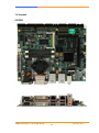
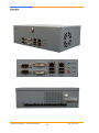
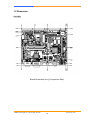
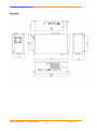
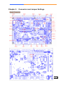
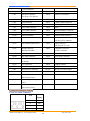
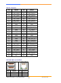
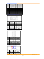
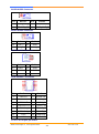
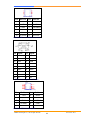
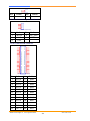
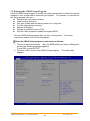
SG A-2210 AMD eOntario Processor based Gaming System, DirectX 11, OpenGL 4, 1 x CFast, 1 x CF, 10 x COM, 2nd RTC and NVRAM/MRAM User’s Manual AEWIN Technologies Co., Ltd. All rights reserved. 1 Ver1.0 Dec. 2013 Table of Contents Chapter 1. General Information .............................................................................3 1.1 Introduction .........................................................................................................3 1.2 Specification ........................................................................................................4 1.3 Precautions ........................................................................................................ 10 1.4 Layout……………… ........................................................................................... 11 1.5 Dimension .......................................................................................................... 13 Chapter 2. Connector and Jumper Settings ....................................................... 15 Chapter 3. BIOS Setup ............................................................................................ 31 3.1 Quick Setup ....................................................................................................... 31 3.2 Entering the CMOS Setup Program ................................................................. 32 3.3 Main .................................................................................................................... 34 3.4 Advanced ........................................................................................................... 35 3.5 Chipset ............................................................................................................... 36 3.6 Boot .................................................................................................................... 37 3.7 Security .............................................................................................................. 38 3.9 Save and Exit Setup .......................................................................................... 39 AEWIN Technologies Co., Ltd. All rights reserved. 2 Ver1.0 Dec. 2013 Chapter 1. General Information 1.1 Introduction SGA-2210 is a graphic-enhanced mainstream gaming system. “Built with AMD eOntario chipsets, SGA-2210 can support fantastic integrated graphic performance and reach 2,500 score while running 3DMark 2006 under 1024 x 768 x 32bits.With UVD 3.0, SGA-2210 can offload video decode dramatically reducing CPU loading during video play. It supports full bit-stream decoding of H.264/MPEG-4 AVC, VC-1, DivX, Xvid, MPEG2, as well as Blu-ray. Key features: GLI compliant Onboard graphic 3DMark 06 up to 2,500 score Support Directx 11 and OpenGL 4 Support full bitstream decoding of H.264/MPEG-4 AVC, VC-1, DivX, Xvid, MPEG2, as well as Blu-ray 3D AC Power Fail Detection w/ interrupt Instant ON/OFF in 500ms Battery Low Detection 10 x COM, 2 x LAN, NVRAM, TPM, 2nd RTC SGA-2210 provides various security mechanisms, including physical security, data security and software security. “AC Power Fail Detection” is one of the important features of data security. With this function, SGA-2210 can write data into NVRAM while unpredictable AC Power Fail, and make sure the data to be secured under any circumstance. AEWIN Technologies Co., Ltd. All rights reserved. 3 Ver1.0 Dec. 2013 1.2 Specification GA-2210 ■ System CPU AMD® T56N Dual Core 1.65GHz BIOS AMI® BIOS Chipset AMD® A55E chipset System Memory 2 x DDR3 SODIMM socket support up to 8GB Watchdog Timer 255 levels timer interval, (1sec. to 255min.), setup by software. ■ Display Video Chipset AMD® T56N w/ ATI® Radeon™ HD6320 - Microsoft® DirectX® 11 - OpenGL 4.0 - OpenCL 1.0 - UVD (Universal Video Decoder) 3.0; Full bitstream decoding of H.264/MPEG-4 AVC, VC-1, DivX, Xvid, MPEG2, as well as Blu-ray 3D Video Interface 1st display Single-link DVI 1920 × 1200 at 60 Hz 2nd display Single-link DVI 1920 × 1200 at 60 Hz(or 2nd display VGA 2048 × 1536 at 60 Hz) ■ Audio Audio Chipset HDA 5.1 Channel Power amp. N/A Audio Interface Front, Surround, CEN/SUB ■ Ethernet Ethernet Interface 2 x PCIe x1 Gigabit Ethernet ■ Storage SSD 1 x CF 1 x CFast 2GB NANDrive (Optional 8GB) HDD Two SATA connectors ■ Security Physical Security Intrusion Detection Onboard Storage Software Security Boot ROM TPM 1.2 FPGA AEWIN Locking AEWIN Technologies Co., Ltd. All rights reserved. 4 Ver1.0 Dec. 2013 Data Security Non-Volatile SRAM, support MRAM H/W Data Mirror Backup AC Power Fail detection w/ interrupt ■Gaming NVRAM On-board Battery Backup SRAM (battery-less MRAM/ FRAM optional) Timers Programmable timer with timeout interrupt Intrusion Detection By battery powered single chip microcontroller Operates with and without system power 8x Intrusion detection inputs Logs date/time of latest 100 events Events include door status, system resets/brownouts, NVRAM battery low, … On-chip EEPROM backup Digital I/O 16 x ESD Protected Input 16 x Photo-coupler Protected Input 28 x 500mA current sink output 4 x 3A current sink output Optional 64 x I/O by request ■ Expansion Expansion slot One PCIe x16 slots ■ System I/O COM 10 x COM (9 bits) ․COM1, COM2 support RS-232 at Rear I/O ․COM3 support RS-232 ․COM4 support RS-485 ․COM5, COM6 support ccTalk ․COM7, COM8, COM9 support simple RS-232 USB I/O ․COM10 support 1x RS-232 8 x USB2.0 - 4 x USB 2.0 port at rear I/O - 4 x USB 2.0 (pin header) 1 x PS2 KB/MS (pin header) ■ Power Supply Voltage ATX compliant ■ Software O/S Windows XP Embedded Linux ■ Mechanical and Environment System Health Measurement of CPU core and system temperature with thermal trip. Monitoring Speed monitoring for CPU fan and two system fans AEWIN Technologies Co., Ltd. All rights reserved. 5 Ver1.0 Dec. 2013 Operating Temperature: 0 – 60 ºC (32 ºF – 140 ºF) Environmental Storage Temperature: -20 – 85 ºC (-4 ºF – 185 ºF) Relative Humidity: 10-85 % RH, non-condensing Compliant FCC/CE Class A GLI Dimension 170mm (L) x 200mm (W) (8.7” L x 11.6” W) ■ Applications Main Application Video slot machines (Class II/III) Video lottery terminals Amusement game machines Master unit of roulette machine Downloadable gaming terminal Multi player gaming machines Order Information Standard GA-2210A AMD T56N Dual Core 1.65GHz based Gaming Board with 1 x CF, 1 x CFast, 10 x COM, 2 x GbE Optional DK-GA2200 Development Kit - R217A Gaming I/O testing board - 46L-G00010-02 Cable of R217A of GA-2200 - 46L-SATA07-00 S-ATA cable - 46L-IPS200-00 KB/MS cable - 46L-IUSB01-00 USB cable - 46L-COM007-00; COM cable * Note: All specifications are subject to change without prior notice AEWIN Technologies Co., Ltd. All rights reserved. 6 Ver1.0 Dec. 2013 SGA-2210 ■ System CPU AMD® T56N Dual Core 1.65GHz BIOS AMI® BIOS Chipset AMD® A55E chipset System Memory 2 x DDR3 SODIMM socket support up to 8GB Watchdog Timer 255 levels timer interval, (1sec. to 255min.), setup by software. ■ Display Video Chipset AMD® T56N w/ ATI® Radeon™ HD6320 - Microsoft® DirectX® 11 - OpenGL 4.0 - OpenCL 1.0 - UVD (Universal Video Decoder) 3.0; Full bitstream decoding of H.264/MPEG-4 AVC, VC-1, DivX, Xvid, MPEG2, as well as Blu-ray 3D Video Interface 1st display Single-link DVI 1920 × 1200 at 60 Hz 2nd display Single-link DVI 1920 × 1200 at 60 Hz(or 2nd display VGA 2048 × 1536 at 60 Hz) ■ Audio Audio Chipset HDA 5.1 Channel Power amp. N/A Audio Interface Front, Surround, CEN/SUB ■ Ethernet Ethernet Interface 2 x PCIe x1 Gigabit Ethernet ■ Storage SSD 1 x CF 1 x CFast 2GB NANDrive (Optional 8GB) HDD Two SATA connectors ■ Security Physical Security Intrusion Detection Onboard Storage Software Security Boot ROM TPM 1.2 FPGA AEWIN Locking Data Security Non-Volatile SRAMm support MRAM H/W Data Mirror Backup AC Power Fail detection w/ interrupt ■Gaming AEWIN Technologies Co., Ltd. All rights reserved. 7 Ver1.0 Dec. 2013 NVRAM On-board Battery Backup SRAM (battery-less MRAM / FRAM optional) Timers Programmable timer with timeout interrupt Intrusion Detection By battery powered single chip microcontroller Operates with and without system power 6x Intrusion detection inputs Logs date/time of latest 100 events Events include door status, system resets/brownouts, NVRAM battery low, … On-chip EEPROM backup Digital I/O 16 x ESD Protected Input 16 x Photo-coupler Protected Input 28 x 500mA current sink output 4 x 3A current sink output Optional 64 x I/O by request ■ Expansion Expansion slot One PCIe x16 slots Mechanical Front I/O - 1 x DVI, 1 x DVI-D 2 x RS-232 2 x LAN 4 x USB 5.1 channel audio Rear I/O - 16 x ESD Protected Input; 16 x Photo-coupler Protected Input - 28 x 500mA current sink output; 4 x 3A current sink output - 2 x RS-232, 1 x RS-485, 2 x ccTalk, 3 x Simple RS-232(Tx, Rx) - 8 x Intrusion Detection ■ Power Supply Power input ATX compliant Power consumption TBD ■ Software O/S Windows XP(e) Linux ■ Mechanical Environment Environmental Operating Temperature: 0 – 40 ºC (32 ºF – 140 ºF) Storage Temperature: -20 – 85 ºC (-4 ºF – 185 ºF) Relative Humidity: 10-85 % RH, non-condensing Compliant CE/FCC Class A GLI Dimension 270mm (W) x 184mm (D) x mm (H) ■ Applications Main Application Video slot machines (Class II/III) Video lottery terminals AEWIN Technologies Co., Ltd. All rights reserved. 8 Ver1.0 Dec. 2013 Amusement game machines Master unit of roulette machine Downloadable gaming terminal Multi player gaming machines Order Information Standard SGA-2210A AMD T56N Dual Core 1.65GHz based Gaming System with 10x COM, 2x GbE, 2MB NVRAM/MRAM, 2MB Boot ROM and TPM Optional DK-GA2210 Development Kit - R217A Gaming I/O testing board - 46L-G00010-02 Cable of R217A of GA-2210 - 46L-SATA07-00 S-ATA cable - 46L-IPS200-00 KB/MS cable - 46L-IUSB01-00 USB cable - 46L-COM007-00; COM cable AEWIN Technologies Co., Ltd. All rights reserved. 9 Ver1.0 Dec. 2013 1.3 Precautions Please make sure you properly ground yourself before handling the GA-2210 board or other system components. Electrostatic discharge can be easily damage the GA-2210 board. Do not remove the anti-static packing until you are ready to install the GA-2210 board. Ground yourself before removing any system component from it protective anti-static packaging. To ground yourself, grasp the expansion slot covers or other unpainted parts of the computer chassis. Handle the GA-2210 board by its edges and avoid touching its component. AEWIN Technologies Co., Ltd. All rights reserved. 10 Ver1.0 Dec. 2013 1.4 Layout GA-2210 AEWIN Technologies Co., Ltd. All rights reserved. 11 Ver1.0 Dec. 2013 SGA-2210 AEWIN Technologies Co., Ltd. All rights reserved. 12 Ver1.0 Dec. 2013 1.5 Dimension GA-2210 Board Dimension (mm) (Component Side) AEWIN Technologies Co., Ltd. All rights reserved. 13 Ver1.0 Dec. 2013 SGA-2210 AEWIN Technologies Co., Ltd. All rights reserved. 14 Ver1.0 Dec. 2013 Chapter 2. Connector and Jumper Settings Board Connector Connector List Connector Description AEWIN Technologies Co., Ltd. All rights reserved. Connector 15 Description Ver1.0 Dec. 2013 CN1 SATA Connector CN12 Test Pin Header CN2 SATA Connector CN13 Audio Connector CN3 Dual DVI Connector CN14 Audio5.1 Pin Header DVI-D(up); DVI-I(down) CN4 Test Pin Header CN15 LPC Port80 Pin Header CN5 Cfast Connector CN16 COM1/COM2 Connector CN6 CF Connector CN17 FPGA Update Pin Header CN7 RJ45+USB Connector CN18 None CN8 RJ45+USB Connector CN19 Intrusion Battery Connector CN9 None CN20 Intrusion Update Pin Header CN10 USB Pin Header CN21 GPIO Extend Connector CN11 PS2 KB/MS Pin Header CN22 GPO Connector (OUT0~OUT27 500mA) CN23 GPI Connector(IN0~IN31) CN24 GPO Connector (OUT28~OUT31 2A) CN25 DOOR Connector CN26 (DOOR0~DOOR6) COM Port Connector (COM3~COM10) CN27 DCIN Connector(+12V) CN28 FAN Connector CN29 ATX 4Pin Connector CN30 ATX 24Pin Connector CN31 Power Button/System Reset CN32 FAN Connector CN34 USB Pin Header Pin Header CN33 DIMM1 FAN Connector DDR3 Slot DIMM2 DDR3 Slot PW1 HDD Power Connector PCI-E1 PCI-E x16 slot(x4 singel) JP1 CMOS Hold / Clear Select JP2 None JP3 FPGA EEPROM JP4 None JP6 DOOR7 Select Write Protect Select JP5 Intrusion Update Voltage Select JP7 SATA NANDrive Write Protect Select Connector/Jumper Setting CN1/CN2: SATA Connector Pin Signal 1 Ground 2 TXP 3 TXN 4 Ground AEWIN Technologies Co., Ltd. All rights reserved. 16 Ver1.0 Dec. 2013 5 RXN 6 RXP 7 Ground CN3A: DVI Connector (DVI-D) CN3A M1 CK1 CK2 CK3 CK4 CK5 CK6 CK7 CK8 CK9 CK10 CK11 CK12 CK13 CK14 CK15 CK16 CK17 CK18 CK19 CK20 CK21 CK22 CK23 CK24 C1 C2 C3 C4 C5 M2 CASE1 TMDS Data2TMDS Data2+ TMDS Data2/4 Shield TMDS Data4TMDS Data4+ DDC Clock DDC Data A VSY NC TMDS Data1TMDS Data1+ TMDS Data1/3 Shield TMDS Data3TMDS Data3+ +5V Power GND(f or +5V) Hot Plug Detct TMDS Data0TMDS Data0+ TMDS Data0/5 Shield TMDS Data5TMDS Data5+ TMDS Clock Shield TMDS Clock+ TMDS ClockRED GREEN BLUE A HSY NC AGND CASE2 DUAL DVI-I Pin Define Pin Define M1 CASE GND M2 CASE GND CK1 DP0_TX0_N CK2 DP0_TX0_P CK3 GND CK4 - CK5 - CK6 DP0_AUX_P CK7 DP0_AUX_N CK8 - CK9 DP0_TX1_N CK10 DP0_TX1_P CK11 GND CK12 - CK13 - CK14 +5V CK15 GND CK16 DVID_HPD CK17 DP0_TX2_N CK18 DP0_TX2_P CK19 GND CK20 - CK21 - CK22 GND CK23 DP0_TX3_N CK24 DP0_TX3_P C1 Analog_R C2 Analog_G C3 - C4 - C5 Analog GND - CN3B: DVI Connector (DVI-I) AEWIN Technologies Co., Ltd. All rights reserved. 17 Ver1.0 Dec. 2013 CN3B M3 CK25 CK26 CK27 CK28 CK29 CK30 CK31 CK32 CK33 CK34 CK35 CK36 CK37 CK38 CK39 CK40 CK41 CK42 CK43 CK44 CK45 CK46 CK47 CK48 C6 C7 C8 C9 C10 M4 CASE1 TMDS Data2TMDS Data2+ TMDS Data2/4 Shield TMDS Data4TMDS Data4+ DDC Clock DDC Data A VSY NC TMDS Data1TMDS Data1+ TMDS Data1/3 Shield TMDS Data3TMDS Data3+ +5V Power GND(f or +5V) Hot Plug Detct TMDS Data0TMDS Data0+ TMDS Data0/5 Shield TMDS Data5TMDS Data5+ TMDS Clock Shield TMDS Clock+ TMDS ClockRED GREEN BLUE A HSY NC AGND CASE2 DUAL DVI-I Pin Define Pin Define M3 CASE GND M4 CASE GND CK25 DP1_TX0_N CK26 DP1_TX0_P CK27 GND CK28 - CK29 - CK30 DP1_AUX_P CK31 DP1_AUX_N CK32 Analog_VSY CK33 DP1_TX1_N CK34 DP1_TX1_P CK35 GND CK36 - CK37 - CK38 +5V CK39 GND CK40 DVII_HPD CK41 DP1_TX2_N CK42 DP1_TX2_P CK43 GND CK44 - CK45 - CK46 GND CK47 DP1_TX3_N CK48 DP1_TX3_P C6 Analog_R C7 Analog_G C8 Analog_B C9 Analog_HSY C10 Analog GND - CN5:CFast Connector AEWIN Technologies Co., Ltd. All rights reserved. 18 Ver1.0 Dec. 2013 CN5/6 S1 S2 S3 S4 S5 S6 S7 GND RX+ RXGND TXTX+ GND PC1 PC2 PC3 PC4 PC5 PC6 PC7 PC8 PC9 PC10 PC11 PC12 PC13 PC14 PC15 PC16 PC17 CDI GND TBD TBD TBD TBD GND LED1 LED2 IO1 IO2 IO3 3.3V 3.3V PGND PGND CDO NC1 NC2 NC3 NC4 NC5 NC6 NC7 NC8 NC1 NC2 NC3 NC4 NC5 NC6 NC7 NC8 CFAST SOCKET Pin Signal S1 GND Pin Signal S2 S3 SATA_TX_N S4 SATA_TX_P GND S5 SATA_RX_N S6 SATA_RX_P S7 GND S8 PC1 - PC2 GND PC3 Test Pin PC4 Test Pin PC5 Test Pin PC6 Test Pin PC7 GND PC8 - PC9 - PC10 - PC11 - PC12 - PC13 +3.3V PC14 +3.3V PC15 GND PC16 GND PC17 - NC1 - NC2 - NC3 - NC4 - NC5 - NC6 - NC7 - NC8 - AEWIN Technologies Co., Ltd. All rights reserved. 19 Ver1.0 Dec. 2013 CN6:CF Connector Pin Define Pin Define 1 GND 26 CF_CD-1 2 IDE_PDD3 27 IDE_PDD11 3 IDE_PDD4 28 IDE_PDD12 4 IDE_PDD5 29 IDE_PDD13 5 IDE_PDD6 30 IDE_PDD14 6 IDE_PDD7 31 IDE_PDD15 7 IDE_PDCS1_N 32 IDE_PDCS3_N 8 GND 33 GND 9 GND 34 IDE_PDIOR_N 10 GND 35 IDE_PDIOW_N 11 GND 36 CF_PIN36 12 GND 37 IDE_IRQ 13 +5V 38 +5V 14 GND 39 GND 15 GND 40 NC 16 GND 41 IDE_RST_N 17 GND 42 IDE_PDIORDY 18 IDE_PDA2 43 IDE_PDDREQ 19 IDE_PDA1 44 IDE_PDDACK_N 20 IDE_PDA0 45 IDE_ACTP_N 21 IDE_PDD0 46 IDE_PDIAG_N 22 IDE_PDD1 47 IDE_PDD8 23 IDE_PDD2 48 IDE_PDD9 24 IDE_CS16_N 49 IDE_PDD10 25 NC 50 GND CN7/CN8:USB and LAN RJ45 Pin 15 16 17 Signal 5VUSB USBDTUSBDT+ Pin 1 2 3 Signal NC MDIP0 MDIN0 AEWIN Technologies Co., Ltd. All rights reserved. 20 Ver1.0 Dec. 2013 18 19 20 21 22 GND1 GND2 GND3 GND4 GND5 GND6 Ground 5VUSB USBDTUSBDT+ Ground Ground Ground Ground Ground Ground Ground 4 5 6 7 8 9 10 11 12 13 14 MDIP1 MDIN1 MDIP2 MDIN2 MDIP3 MDIN3 Ground LINK LED ACT LED 1G LED 100 LED CN10 & CN34: USB pin header Pin Define Pin Define 1 +5V 2 +5V 3 USBDATA- 4 USBDATA- 5 USBDATA+ 6 USBDATA+ 7 GND 8 GND 9 Reser ved 10 GND CN11: PS/2 KB/MS pin header Pin Define Pin Define 1 KCLK 2 MCLK 3 KDAT 4 MDAT 5 Reser ved 6 NC 7 GND 8 GND 9 +5V 10 +5V CN13A:AUDIO Connector 5 4 3 2 CN13A AUDIO JACK(HD) Pin Define Pin Define 2 MIC_L 3 GND 4 MIC_JD 5 MIC_R AEWIN Technologies Co., Ltd. All rights reserved. 21 Ver1.0 Dec. 2013 CN13B:AUDIO Connector 25 24 23 22 CN13B AUDIO JACK(HD) Pin Define Pin Define 22 SPKR_OUT_L 23 24 FRONT_JD GND 25 SPKR_OUT_R CN13C:AUDIO Connector 35 CN13C 34 33 32 1 AUDIO JACK(HD) Pin Define Pin Define 32 LINE_L 33 GND 34 LINE_JD 35 LINE_R CN13D:AUDIO Connector CN13D NC CGND1 CGND2 CGND3 CGND4 NC CGND1 CGND2 CGND3 CGND4 AUDIO JACK(HD) Pin Define Pin Define C1 GND C2 GND C3 GND C4 GND NC - CN14:AUDIO5.1 Connector CN14 1 3 5 7 9 11 13 15 1 3 5 7 9 11 13 15 2 4 6 8 10 12 14 16 2 4 6 8 10 12 14 16 AUDIO CON(2x8-2mm) Pin Define Pin Define 1 CEN-JD 2 SURR-JD 3 CENTER OUT 4 SURR_L 5 LEF OUT 6 SURR_R 7 SIDESURR-JD 8 FRONT-JD 9 SURBACK_R 10 FRONT_R 11 SURBACK_L 12 FRONT_L 13 +12V 14 GNDAUD 15 +12V 16 GNDAUD CN15: LPC 80 port pin header AEWIN Technologies Co., Ltd. All rights reserved. 22 Ver1.0 Dec. 2013 CN15 1 3 5 7 9 11 2 4 6 8 12 HEADER 2X6(2MM) Pin Define Pin Define 1 +12V 2 LAD0 3 LAD1 4 LAD2 5 LAD3 6 LFRAME# 7 RST# 8 +5V 9 CLK 10 Reser ved 11 Ground 12 Ground CN16:COM1 and COM2 Connector Pin Signal Pin Signal A1 DCD1 B1 DCD2 A2 RXD1 B2 RXD2 A3 TXD1 B3 TXD2 A4 DTR1 B4 DTR2 A5 Ground B5 Ground A6 DSR1 B6 DSR2 A7 RTS1 B7 RTS2 A8 CTS1 B8 CTS2 A9 RI1 B9 RI2 CN17: FPGA Update Pin Header CN17 1 3 5 7 9 2 6 8 10 Pin Header 2*5(2.54mm) Pin Define Pin Define 1 TCK 2 GND 3 TDO 4 NC 5 TMS 6 VJTAG 7 VPUMP 8 TRST 9 TDI 10 GND CN19:BATTERY HEADER AEWIN Technologies Co., Ltd. All rights reserved. 23 Ver1.0 Dec. 2013 1 2 Pin Define Pin Define 1 +3.0V 2 GND CN20: INTRUSION Update Pin Header CN20 1 2 3 4 5 HEADER 1X5(2.54mm) Pin Define Pin Define 1 MCLR 2 PIC_VCC 3 GND 4 PGD 5 PGC CN21: GPIO Extend Connector CN21 1 3 5 7 9 11 13 15 17 19 21 23 25 27 29 31 33 35 37 39 41 43 45 47 49 2 4 6 8 10 12 14 16 18 20 22 24 26 28 30 32 34 36 38 40 42 44 46 48 50 HEADER 2*25 BOX(2mm) Pin Define Pin Define 1 EXT0 2 DQ0 3 EXT1 4 DQ1 5 EXT2 6 DQ2 7 EXT3 8 DQ3 9 EXT4 10 DQ4 11 EXT5 12 DQ5 13 EXT6 14 DQ6 15 EXT7 16 DQ7 17 EXT8 18 RA0 19 EXT9 20 RA1 21 EXT10 22 RA2 23 EXT11 24 RA3 AEWIN Technologies Co., Ltd. All rights reserved. 24 Ver1.0 Dec. 2013 25 EXT12 26 RA4 27 EXT13 28 RA5 29 EXT14 30 RA6 31 EXT15 32 RA7 33 IOSel* 34 RA8 35 W E* 36 RA9 37 OE* 38 RA10 39 RA12 40 RA11 41 RA13 42 GND 43 GND 44 GND 45 GND 46 GND 47 +5V 48 +5V 49 +5V 50 +5V CN22:GPO Connector(0~27) Mosfet Open Drain 500mA Output CN22 1 3 5 7 9 11 13 15 17 19 21 23 25 27 2 4 6 8 10 12 14 16 18 20 22 24 26 28 30 32 34 31 33 BH34R-6T_P29NC Pin Define Pin Define 1 OUT1 2 OUT0 3 OUT3 4 OUT2 5 OUT5 6 OUT4 7 OUT7 8 OUT6 9 OUT9 10 OUT8 11 OUT11 12 OUT10 13 OUT13 14 OUT12 15 OUT15 16 OUT14 17 OUT17 18 OUT16 19 OUT19 20 OUT18 21 OUT21 22 OUT20 23 OUT23 24 OUT22 25 OUT25 26 OUT24 AEWIN Technologies Co., Ltd. All rights reserved. 25 Ver1.0 Dec. 2013 27 OUT27 OUT26 28 29 Reser ved 30 +12V 31 GND 32 +12V 33 GND 34 +12V CN23:GPI Connector(0~31) CN23 1 3 5 7 9 11 13 15 17 19 21 23 25 27 29 31 33 2 4 6 8 10 12 14 16 18 20 22 24 26 28 30 32 34 BH34R-6T Pin Define Pin Define 1 Iso-IN1 2 Iso-IN0 3 Iso-IN3 4 Iso-IN2 5 Iso-IN5 6 Iso-IN4 7 Iso-IN7 8 Iso-IN6 9 Iso-IN9 10 Iso-IN8 11 Iso-IN11 12 Iso-IN10 13 Iso-IN13 14 Iso-IN12 15 Iso-IN15 16 Iso-IN14 17 TTL-IN17 18 TTL-IN16 19 TTL-IN119 20 TTL-IN18 21 TTL-IN21 22 TTL-IN20 23 TTL-IN23 24 TTL-IN22 25 TTL-IN25 26 TTL-IN24 27 TTL-IN27 28 TTL-IN26 29 TTL-IN29 30 TTL-IN28 31 TTL-IN31 32 TTL-IN30 33 GND 34 +12V CN24:GPO Connector(28~31) Mosfet Open Drain 2A Output CN24 4 5 6 1 2 3 BTX06PTR1 Pin Define Pin Define AEWIN Technologies Co., Ltd. All rights reserved. 26 Ver1.0 Dec. 2013 1 OUT28 2 +12V 3 OUT30 4 OUT29 5 GND 6 OUT31 CN25:DOOR Connector(0~6) CN25 1 3 5 7 9 2 4 6 8 10 BH10R-6T Pin Define Pin Define 1 DOOR1 2 DOOR0 3 DOOR3 4 DOOR2 5 DOOR5 6 DOOR4 7 Reser ved 8 DOOR6 9 GND 10 GND CN26:COM PORT Connector(COM3~COM10) CN26 1 3 5 7 11 13 15 17 19 21 23 25 27 29 31 33 2 4 6 8 10 12 14 16 18 20 22 24 26 28 30 32 34 BH34R-6T_P9NC Pin Define Pin Define 1 DCD3#I N 2 DSR3#IN 3 RXD3IN 4 RTS3#OUT 5 TXD3OUT 6 CTS3#IN 7 DTR3#OUT 8 RI3#IN 9 Reserved 10 GND 11 485RX- 12 485TX- 13 485RX+ 14 485TX+ 15 GND 16 GND 17 CCTALK2 18 CCTALK1 19 Reserved 20 S_SIN7 21 S_SIN8 22 S_SOUT7 23 S_SOUT8 24 S_SIN9 25 GND 26 S_SOUT9 27 DCD10#IN 28 DSR10#IN AEWIN Technologies Co., Ltd. All rights reserved. 27 Ver1.0 Dec. 2013 29 RXD10IN 30 RTS10#OUT 31 TXD10OUT 32 33 DTR10#OUT 34 CTS10#IN RI10#IN CN27:+12V DC IN Connector CN27 1 2 POWER_2P Pin Define Pin Define 1 +12V 2 GND CN29:4PIN ATX POWER CONNN 4 12V GND 3 2 1 12V GND Pin Define Pin Define 1 Ground 2 Ground 3 +12V 4 +12V CN30:24PIN ATX POWER CONNN 13 3_3V ATX 3_3V 1 14 -12V 3_3V 2 15 GND GND 3 16 PS_0N 5V 4 17 GND GND 5 18 5V 6 GND 19 GND GND 7 20 RSVD PW_OK 8 21 5V 5VSB 9 22 5V 12V 10 23 5V 12V 11 24 GND 3_3V 12 Pin Define Pin Define 1 +3.3V 2 +3.3V 3 Ground 4 +5V 5 Ground 6 +5V 7 Ground 8 PW_OK 9 5VSB 10 +12V 11 +12V 12 +3.3V 13 +3.3V 14 +12V 15 Ground 16 PS_ON 17 Ground 18 Ground 19 Ground 20 RSVD AEWIN Technologies Co., Ltd. All rights reserved. 28 Ver1.0 Dec. 2013 21 +5V 22 +5V 23 +5V 24 Ground PW1:IDE Power Connector Pin Define Pin Define 1 +12V 2 Ground 3 Ground 4 +5V JP1:CLEAR CMOS Pin Setting NORMAL 1-2 2-3 (Default) CLEAR CMOS JP3: FPGA EEPROM Write Protect Select Pin Setting 1-2 2-3 Write Protect Enable Write Protect Disable (Default) JP5: Intrusion Voltage Select Pin Setting 1-2 2-3 AEWIN Technologies Co., Ltd. All rights reserved. +5V +3.3V (Default) 29 Ver1.0 Dec. 2013 JP6:DOOR7 Status Pin Setting OPEN DOOR7 OFF CLOSE DOOR7 ON JP7:SATA NANDrive Write Protect Select Pin Setting 1-2 2-3 Write Protect Disable (Default) Write Protect Enable AEWIN Technologies Co., Ltd. All rights reserved. 30 Ver1.0 Dec. 2013 Chapter 3. BIOS Setup The BIOS is a set of permanently recorded program routines that give the system its fundamental operational characteristics. It also tests the computer and determines how the computer reacts to instructions that are part of programs. The BIOS is made up of code and programs that provide the device-level control for the major I/O devices in the system. It contains a set of routines (called POST, for Power-On Self Test) that check out the system when you turn it on. The BIOS also includes CMOS Setup program, so no disk-based setup program is required CMOS RAM stores information for: Date and time Memory capacity of the main board Type of display adapter installed Number and type of disk drives The CMOS memory is maintained by battery. By using the battery, all memory in CMOS can be retained when the system power switch is turned off. The system BIOS also supports easy way to reload the CMOS data when you replace the battery of the battery power lose. 3.1 Quick Setup In most cases, you can quickly configure the system by choosing the following main menu options: 1. Choose “Load Optimized Defaults” from the main menu. This loads the setup default values from the BIOS Features Setup and Chipset Features Setup screens. 2. Choose “Standard COS Features” from the main menu. This option lets you configure the date and time, hard disk type, floppy disk drive type, primary display and more. 3. In the main menu, press F10 (“Save & Exit Setup”) to save your changes and reboot the system. AEWIN Technologies Co., Ltd. All rights reserved. 31 Ver1.0 Dec. 2013 3.2 Entering the CMOS Setup Program Use the CMOS Setup program to modify the system parameters to reflect the options installed in your system and to customize your system. For example, you should run the Setup program after you: Received an error code at startup Install another disk drive Use your system after not having used it for a long time Find the original setup missing Replace the battery Change to a different type of CPU Run the Flash program to update the system BIOS Run the CMOS Setup program after you turn on the system. instructions explain how to use the program. On-screen Enter the CMOS Setup program’s main menu as follows: 1. Turn on or reboot the system. After the BIOS performs a series of diagnostic checks, the following message appears: “Press DEL to enter SETUP” 2. Press the <DEL> key to enter CMOS Setup program. The main menu appears: AEWIN Technologies Co., Ltd. All rights reserved. 32 Ver1.0 Dec. 2013 3. Choose a setup option with the arrow keys and press <Enter>. following sections for a brief description of each setup option. See the In the main menu, press F10 (“Save & Exit Setup) to save your changes and reboot the system. Choosing “EXIT WITHOUT SAVING” ignores your changes and exits the program. Pressing <ESC> anywhere in the program returns you to the main menu. AEWIN Technologies Co., Ltd. All rights reserved. 33 Ver1.0 Dec. 2013 3.3 Main Use the Main Setup option as follows: 1. Choose “Main” from the main menu. The following screen appears: 2. Use the arrow keys to move between fields. Modify the selected field using the PgUP/PgDN/+/- keys. Some fields let you enter numeric values directly. Option Date (mm:dd:yy) Time (hour:min:sec) Description Type the current date Type the current time (24-hour clock) 3. After you have finished with the Standard CMOS Features program, press the <ESC> key to return to the main menu. AEWIN Technologies Co., Ltd. All rights reserved. 34 Ver1.0 Dec. 2013 3.4 Advanced Use the Advanced option as follows: 1. Choose “Advanced ” from the main menu. The following screen appears: 2. Use the arrow keys to move between items and to select values. Modify the selected fields using the PgUP/PgDN keys. Press the <F1> “Help” key for information on the available options: Option Description ACPI Configuration It allows you to configure the parameter of ACPI, includes suspend, USB wakeup and etc... Trusted Configuration It allows you to configure the parameter of Trusted, includes TPM and etc... IDE Configuration It allows you to configure the parameter of IDE, includes PIO mode, DMA mode, LBA, SMART and etc... USB Configuration It allows you to configure the parameter of USB. Second SuperIO Configuration It allows you to configure the parameter of SuperIO, includes serial ports and watchdog. SuperIO Configuration It allows you to configure the parameter of SuperIO, includes serial ports and watchdog. USB Configuration It allows you to configure the parameter of USB. AEWIN Technologies Co., Ltd. All rights reserved. 35 Ver1.0 Dec. 2013 3.5 Chipset Use the Chipset option as follows: 1. Choose “Chipset” from the main menu, the following screen appears. 2. Move between items and select values by using the arrow keys. Modify the selected fields using the PgUP/PgDN keys. For information on the various options, please press <F1> key. Option NorthBridge Description It allows you to configure the parameter of NorthBridge, includes clock, timing, VGA frame buffer and etc... NorthBridge LVDS Config It allows you to configure the parameter of LVDS SouthBridge It allows you to configure the parameter of SoughBridge, includes LAN, Audio and etc… AEWIN Technologies Co., Ltd. All rights reserved. 36 Ver1.0 Dec. 2013 3.6 Boot Use the Boot option as follows: 1. Choose “Boot” from the main menu. The following screen appears: 2. Move between items and select values by using the arrow keys. Modify the selected fields using the PgUP/PgDN keys. Please press the <F1> key for information on the various options. Option Boot Configuration Set Boot Priority Description It allows you to configure the parameter of Boot, includes Bootup Num-Lock and etc.. It allows you to configure the sequence of Boot Device AEWIN Technologies Co., Ltd. All rights reserved. 37 Ver1.0 Dec. 2013 3.7 Security Use the Security option as follows: 1. Choose “Security” from the main menu. The following screen appears. This section allows change the password of the supervisor and user. 2. Move between items and select values by using the arrow keys. Modify the selected field the PgUP/PgDN keys. For information on the various options, press <F1> key. AEWIN Technologies Co., Ltd. All rights reserved. 38 Ver1.0 Dec. 2013 3.9 Save and Exit Setup This function automatically saves all CMOS values before exiting Setup. AEWIN Technologies Co., Ltd. All rights reserved. 39 Ver1.0 Dec. 2013