1
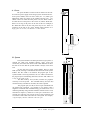
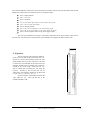
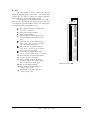
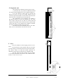
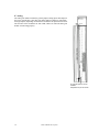
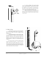
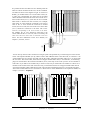
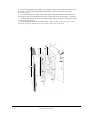
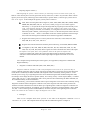
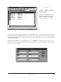
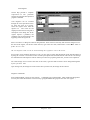
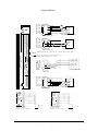
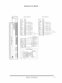
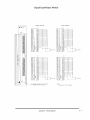
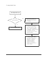
It is possible to have more than one servo module power the
same servo motor if needed. In this case, the servo modules
are linked as shown in the diagram at right. To each servo
module, you should attach a servo motor linker cable (see
I). Then, the corresponding wire from each of the linker
cables should be attached to the same section of the servo
motor linker block (see 2). (Note that the servo module
linker block is divided into four sections.) For example,
each of the “R” wires should be connected to one section,
each of the “S” wires should be connected to another
section, and so on. Then, the wires of the servo motor cable
(see 3) should be connected to the other side of the
connector, corresponding to the correct section of the block.
For example, the “R” wire should be connected to the
section where all the “R” wires are, and so on. Finally, the
other end of the servo motor cable is connected to the servo
motor. For more information on the servo module, see
Chapter 1, section E, “Servo”.
r
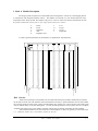
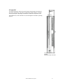
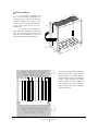
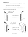
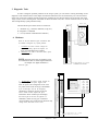
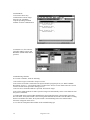
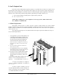
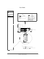
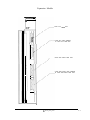
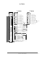
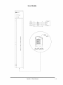
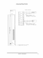
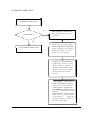
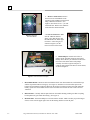
You can have up to three racks connected in a Target system. One potential way of connecting two racks is shown
below. The expansion module (see 1), which is used to link additional racks to the main rack, is connected to the
system module (see 2) as shown. Note that only the first cable, called the rack linker cable (see 3), is used to link
the two racks. The second cable, called the servo/stepper module linker cable, is not used here, so terminating
plugs are inserted where the connection should be (see 4). This setup occurs when you have an axis module in
both racks. If you had an axis module only in the first rack, and you wanted this axis module to control servo
modules in the second rack as well as the first rack, you would then use the servo/stepper module linker cable as
well as the rack linker cable to link the two racks. Also note that a terminating plug (see 5) is inserted at the place
where there would otherwise be a connection to a third rack. For other information on the expansion module, see
Chapter 1, section C, “Expansion”.
t
::::0
:-::
I:::
0
0
::ii
i;
ii
0
0
:::-::
:-ii
::
0
0
i:::
iiii
::
0
0
_--
i
-
7
Installation & Expansion
2-3