1
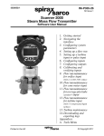
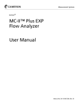
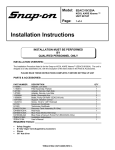
Quick Start Guide
MC-III Flow Analyzer
TM
A Quick Reference on
Mounting, Wiring, & Configuring
the MC-III EXP or WP Flow Analyzer
For complete instructions, see
MC-III EXP User Manual, Part No. 9A-50165003
MC-III WP User Manual, Part No. 9A-50165009
in the MC-III software Help menu
Part No. 2296694-01, Rev. 03
Mounting Your MC-III
MC-III EXP
1. Position the MC-III EXP above the flowmeter pickup adapter.
2. Plug the connector of the MC-III EXP cable into the magnetic pickup and
hand-tighten the knurled nut on the connector.
3. Mount the MC-III EXP on the flowmeter pickup adapter with the display
facing the desired direction, and tighten all sections of the pipe union.
Before mounting an ATEX-approved device, see “MC-III EXP (ATEX)”
below.
Pipe plugs
Caution: Do not use Teflon tape on
threads of the union, adapter, or pipe
plugs.
MC-III EXP (ATEX)
ATEX-approved MC-III EXPs are fitted
with a standoff tube adapter when purchased with an ATEX-approved Barton
7000 Series or NuFlo turbine meter.
Explosion-proof
enclosure
To avoid damaging the signal cable
during installation, make sure the
signal cable is disconnected from the
MC-III circuit board before mounting
the MC-III to a flowmeter.
3/4-in. to 1-in.
pipe reducer*
1-in. pipe union*
Cable
assembly
ATEX-approved
standoff tube
adapter
Magnetic pickup
Turbine flowmeter
* Pipe reducer and union are used in
CSA-approved MC-III devices only.
2
MC-III WP
1. Position the MC-III WP above the flowmeter.
2. Plug the MC-III WP cable connector into the magnetic pickup and handtighten the knurled nut on the connector.
3. Screw the MC-III WP mount onto the flowmeter threads surrounding the
magnetic pickup.
4. With the display facing
the desired direction,
tighten the two screws
on either side of the
mount to prevent
horizontal shifting.
5. With the display
oriented vertically in
the desired direction,
tighten the two hexhead bolts on either
side of the top section
of the mount to prevent
vertical shifting.
3
Wiring Your MC-III
CAUTION—All field wiring must conform to the National Electrical Code, NFPA 70,
Article 501-4(b) for installations within the United States or the Canadian Electric
Code for installations within Canada. Local wiring ordinances may also apply. All
field wiring must have a wire range of 22 to 14 AWG and terminal block screws must
be tightened to a minimum torque of 5 to 7 in-lb to secure the wiring within the terminal block. Only personnel who are experienced with field wiring should perform
these procedures.
Pipe plugs
MC-III EXP
Field wiring enters the MC-III EXP
enclosure through either of two
threaded conduit openings in the
top of the enclosure. When not in
use, the openings are sealed with
pipe plugs.
Ground
screws
MC-III WP
Field wiring enters the MC-III WP
enclosure through conduit hubs in
the bottom of the enclosure. One
hub is supplied and two additional
entrances are plugged but available for use with customer-supplied
hubs). The flowmeter cable is
routed through a cord connector in
the back of the bottom enclosure
panel.
For Div. 2 installations, a ground
wire must be connected to the
internal ground screw inside the
enclosure.
For DC-powered installations, route
the ground conductor into the
enclosure with the incoming power
conductors.
4
Ground screw
1. If the battery/battery pack is not already connected to the circuit board,
attach the battery cable to connector J1.
2. Connect the flowmeter signal cable to terminal block TB1.
6-3
0V
DC
BATTERY
BATTERY CONNECTION
TB
A&S
3
EXT POWER
GND
J1
TFM
B
TURBINE
MAGNETIC PICKUP
VMAX = 3.9 V
RESET
INPUT
A
PULSE
INPUT
TB1
RESET
SWITCH
J2
3. If an external power supply is to be used (the battery will provide backup
power), wire the power supply to terminal block TB3.
For MC-III WP Div. 2 installations, connect a protective overcurrent
device rated at 0.5A maximum (circuit breaker or fuse) to the positive
supply line of the DC power supply in the safe area. A disconnect switch
for the power supply must also be installed in the safe area.
VD
C
EXT POWER
GND
A&S
4-20
OUT
RS485 PULSE
SLAVE OUT
RESET
INPUT
TFM
TB2
PULSE
INPUT
TB1
TB
3
J1
6-3
0
BATTERY
A Zener diode (Part No. 1.5KE33CA) must be installed for CE approval.
POWER
SUPPLY
6 to 30
VDC
GROUND SCREW
REQUIRED FOR
DIV. 2 INSTALLATIONS
TB3 MARKING:
GND = SIGNAL GROUND
RESET
SWITCH
J2
Caution: Never use external power
with a 4-20 mA output.
5
Wiring Your MC-III
4. If a pulse output is to be used, wire the power supply and the pulse
readout device to terminal block TB2. The maximum current rating of the
pulse output circuit is 60 mA at 50 VDC.
J1
6-3
0V
DC
BATTERY
A Zener diode (Part No. 1.5KE56CA) must be installed for CE approval.
EXT POWER
GND
* Resistor may be included in pulse readout
device. Size the resistor to limit the current
to 60 mA.
TB
3
A&S
TB1
TB2
RESET
INPUT
RS485 PULSE
SLAVE OUT
PULSE
INPUT
TFM
4-20
OUT
*
Leave this
end of shield
disconnected.
POWER SUPPLY
5 to 50 VDC
RESET
SWITCH
PULSE READOUT
DEVICE
J2
VD
C
EXT POWER
GND
A&S
4-20
OUT
RS485 PULSE
SLAVE OUT
RESET
INPUT
TFM
TB2
PULSE
INPUT
TB1
TB
3
J1
6-3
0
BATTERY
5. If a 4-20 mA rate output is to be used, wire the power supply to terminal
block TB2. The power supply voltage required to power the current loop
depends on the loop resistance. See an MC-III user manual for details.
POWER SUPPLY
8 to 30 VDC
*Resistor may be
* LOAD
RESET
SWITCH
J2
Caution: Never use external power with a 4-20 mA output.
6
included in readout
device.
4-20 mA and
flowmeter frequency
(amp & square)
cannot be used
simultaneously.
6. If a flowmeter frequency output is to be used to provide flow rate and/
or total information to peripheral equipment, wire the power supply and
the frequency readout device to terminal block TB3. The readout device
must operate with 50 mA or less.
*
Leave this
end of shield
disconnected.
EXT POWER
GND
A&S
4-20
OUT
RS485 PULSE
SLAVE OUT
RESET
INPUT
TFM
TB2
PULSE
INPUT
TB1
FREQUENCY
READOUT DEVICE
TB
3
J1
POWER SUPPLY
5 to 30 VDC
6-3
0V
DC
BATTERY
TB3 MARKINGS:
GND = SIGNAL GROUND
A&S = AMP & SQUARE
* Resistor may be included in frequency
readout device. Size the resistor to limit
the current to 50 mA.
4-20 mA and flowmeter frequency
(amp & square) cannot be used
simultaneously.
RESET
SWITCH
J2
Caution: When using the flowmeter frequency output
and powering the device from an external power
supply, make sure both power supplies share a
common negative (-) terminal or are totally isolated
from each other.
7. To configure the MC-III with software, connect the MC-III to a computer
by wiring a converter cable to the RS-485 terminals of TB2. See page 12
for wiring diagrams.
7
Configuring with the Keypad
Most routine functions can be configured from the six-button keypad.
This guide provides instructions for entering a calibration factor, and selecting
the units for the total and flow rate displays. For instructions on configuring all
other parameters, see the MC-III user manuals.
8
Parameter changes typically require four basic steps:
1. Select a menu (K-FACTOR, OUTPUT, OR DISPLAY).
2. Press UP ARROW to change the parameter or value displayed.
3. Press LEFT ARROW to advance to the next configurable
parameter or value.
4. Press ENTER to save the new configuration setting.
Enter a
Calibration Factor
00000000
CF
X1000
CF
X1000
M
BBL
GAL
LIT
3
Select a K-Factor Unit.
Press K-FACTOR MENU.
Press UP ARROW until the
correct unit is displayed.
Select a Decimal Point Position.
Press LEFT ARROW to select
the decimal point.
Press UP ARROW to change the
position of the decimal point.
Press LEFT ARROW to save the
decimal point selection and
proceed with entering a calibration factor.
Enter a Calibration Factor.
Press UP ARROW until the last
digit of the calibration factor is
displayed.
Then press LEFT ARROW to
select the next digit to the left.
Repeat using UP and LEFT
arrows to enter remaining digits.
Press ENTER to advance to the
Input Sensitivity menu.
K-FACTOR
MENU
TEST
LOG
TEST
LOG
TEST
LOG
ENTER
SAVE
Enter an Input Sensitivity Setting.
Press UP ARROW to select low,
medium, or high (for a turbine
TEST
meter input signal) or “pulse
input” (for a preamplifier input
signal).
Press ENTER to save your
ENTER
selections.
SAVE
9
Configuring with the Keypad
Select a Unit of Measure for Volume
00000000
CF
X1000
CF
X1000
3
M
BBL
GAL
LIT
STANDARD
3
M
BBL
GAL
LIT
000000
/SEC
/MIN
/HR
/DAY
Select a Volume Unit.
Press DISPLAY MENU.
Press UP ARROW until the correct unit is displayed.
Note—If a calculated divisor was entered, select user-defined (no
units visible).
To read the volume in terms of thousands of units (ex. 1.0 = 1,000
bbl), continue pressing UP ARROW until both the unit of choice
and the X1000 option are displayed.
DISPLAY
MENU
TEST
TEST
Select a Decimal Point Position.
Press LEFT ARROW until the decimal point in the Total display
begins blinking.
LOG
Press UP ARROW to change the position of the decimal point.
TEST
Press ENTER to save your selections.
ENTER
SAVE
10
Select a Unit of Measure for Rate
00000000
CF
X1000
CF
X1000
3
M
BBL
GAL
LIT
STANDARD
3
M
BBL
GAL
LIT
000000
00000000
CF
X1000
CF
X1000
3
M
BBL
GAL
LIT
STANDARD
/SEC
/MIN
/HR
/DAY
3
M
BBL
GAL
LIT
000000
/SEC
/MIN
/HR
/DAY
Select the Volume Portion of the Flow Rate Unit.
Press DISPLAY MENU.
Press LEFT ARROW until a volume unit of measure is displayed in
the rate display portion of the LCD window. These units are located
to the left or just above the Rate display.
Press UP ARROW until the desired unit of measure is displayed.
Note—If a calculated divisor was entered, select user-defined
(no units visible).
DISPLAY
MENU
LOG
TEST
Select the Time Portion of the Flow Rate Unit.
Press LEFT ARROW to select the time portion of the Rate unit of
measure.
LOG
Press UP ARROW until the desired unit of measure is displayed.
TEST
Select a Decimal Point Position.
Press LEFT ARROW until the decimal point in the Rate display
begins blinking.
LOG
Press UP ARROW to change the position of the decimal point.
TEST
Press ENTER to save your selections.
ENTER
SAVE
11
Connecting to the MC-III
Step 1: Install the MC-III Software
Follow the instructions on the cover of the CD packet to
load the software. An MC-III icon will appear on the
computer desktop when installation is complete.
Step 2: Connect the Computer to the MC-III
Note—An RS-485 converter is required to connect a computer to the
MC-III flow analyzer. The instructions below are for an RS-485-to USB
converter (Part No. 2296650-01). An RS-485-to-RS-232 9-pin converter
(Part No. 9A-101283116) is also available.
1. Remove or open the cover of the MC-III enclosure to access the circuit
board.
2. Verify that the battery is connected to the J1 connector (page 5). If using
an external power supply, verify that it is wired properly (page 5).
3. Connect the RS-485 to USB converter cable to the RS-485 terminals on
TB2 of the MC-III circuit board as shown.
4. Use a universal A/B USB cable to connect your computer to the converter.
TB2
4-20 RS485 PULSE
OUT SLAVE OUT
TX+
TX-
TD ( B)
TD (A )
GND
Part No. 2296650-01
UNIVERSAL
A/B USB CABLE
Communication Adapters (RS-485 or USB)
If an optional communication adapter is installed, the MC-III EXP may be
connected to a computer without opening the enclosure or installing additional field wiring. Communication adapters are available for use with RS-232 or
USB computer ports. If using a USB port, a user-supplied universal serial bus
USB A/B cable is required. See the MC-III EXP User Manual for details.
Important—The RS-485 to RS-232 adapter is approved for use with
CSA-certified and ATEX-certified MC-III EXP analyzers. The RS-485 to
USB adapter is approved only for use with a CSA-certified MC-III EXP
analyzer.
12
Step 3: Run the Program
1. Double-click the MC-III icon on the desktop or select Start-ProgramsNuFlo-MC-III-MC-III to launch the software.
A Welcome screen will appear, followed by a Device Autorun Options
screen.
2. Select Launch the Configuration Wizard and follow the instructions
on the screen.
For access to all configurable parameters, select Go to MC-III Main
(see the MC-III user manuals for instructions).
To automate a function to run each time the software connects with
the instrument, click on the function on the Device Autorun Options
screen and check the Always do... checkbox at the bottom of the
screen.
13
Configuring with Software
Gas Volume Correction
Gas turbine meters measure gas in actual cubic feet (ACF). To measure
gas in terms of standard cubic feet (SCF), flowing gas pressures and
temperatures must be referenced back to standard conditions, based on
fixed (average) parameters. These parameters are accessible only through
MC-III interface software.
To configure the instrument to measure gas flow in standard cubic feet,
perform the following steps:
1. Select Go to MC-III Main from the Device Autorun Options screen.
2. Click the K-Factor Entry icon in the scroll bar at left.
3. In the Gas Volume Correction section of the K-Factor Entry screen,
check the Enable volume correction checkbox (see screen on page 15).
The STANDARD annunciator will appear on the LCD.
4. Adjust atmospheric pressure, if desired.
5. Enter the base pressure and unit and the base temperature and unit.
6. Enter the working pressure, working temperature, and corresponding
units.
7. Enter a known compressibility factor, or press Calculate compressibility
from gas comp. to enter the gas composition. Click Calculate.
8. Press Apply or OK to save the new compensation settings.
14
Multipoint Linearization
The MC-III can be calibrated with up to 12 calibration points using MC-III
interface software. (Only single-point calibration is supported through the
Configuration Wizard.)
To configure the instrument with these parameters, perform the following
steps: 1. Select Go to MC-III Main from the Device Autorun Options screen.
2. Click the K-Factor Entry icon in the scroll bar at left (see screen on page
14).
3. Select the factor units.
4. Select the multipoint checkbox.
5. Enter the number of calibration points desired using the “plus” and
“minus” buttons (up to 12 points maximum).
6. Click on each activated calibration point field, and enter the appropriate
frequency (Hz) and calibration factor.
7. Repeat for all calibration points.
8. Press Apply or OK to save the new calibration settings.
15
MEASUREMENT SYSTEMS
HOUSTON
HEAD OFFICE
281.582.9500
NORTH
AMERICA
1.800.654.3760
ASIA
PACIFIC
+603.5569.0501
EUROPE,
MIDDLE EAST
& AFRICA
[email protected]
[email protected]
+44.1243.826741
[email protected]
USA • CANADA • UK • CHINA • UAE • ALGERIA • MALAYSIA • INDIA • RUSSIA
www.c-a-m.com/flo
Copyright 2013 Cameron International Corporation