1
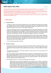
Mx1
SuperLite Mount
Back Cushion
Installation/User Manual
DEALER: This manual contains important safety, Installation and Set-up information
specific to the Invacare Matrx Mx1 SuperLite Mount Back. This Manual MUST be
given to the user of the product.
BEFORE using this product, please read through the instructions carefully and
save for future reference.
TRD0317-00
This product complies with Directive 93/42/EEC concerning medical devices.
The launch date of this product is stated in the CE declaration of conformity.
© 2012 Motion Concepts. All rights reserved. Republication, duplication or modification in whole or in part is prohibited without prior written permission from Motion Concepts. Trademarks are identified by ™ and ®. All trademarks are
owned by or licensed to Motion Concepts or its subsidiaries unless otherwise noted.
-3-
Table of Contents
1.0
General
1.1
1.2
1.3
Symbols
Overview
Limited Warranty
2.0
Safety
2.1
2.2
2.3
2.4
2.5
General Guidelines
Intended Use
Installation Information
Operating Information
Weight Limitations and Model Numbers
3.0
Installation Overview
4.0
Tools Required
5.0
Mx1 SuperLite Mount Installation
5.1
Installation Instructions
6.0
Options
6.1
6.2
6.3
6.4
Installing/Adjusting the Lumbar Support
Plug Inserts
Adhesive Pads
Installing Optional Privacy Flap
7.0
Maintenance
7.1
7.2
7.3
Cleaning
Inspection
Re-Use
-4-
1.0 General
1.1 Symbols
Installing your Invacre-Matrx Seating Series product safely depends upon your diligence in following the
warnings, cautions and information provided in this Installation Manual.
Signal words are used in this manual and apply to hazards or unsafe practices which could result in personal
injury or property damage. See the information below for definitions of the signal words.
WARNING!
• Warning indicates a potentially hazardous situation which, if not avoided, could result in death or
serious injury.
CAUTION!
Caution indicates a potentially hazardous situation which, if not avoided, may result in property damage or minor injury or both.
IMPORTANT!
• Important information and/or instructions to remember when installing and/or adjusting your
Invacare-Matrx Seating Series product .
NOTE:
• Notes indicate useful tips, recommendations and information for efficient, trouble-free use.
Requirements:
• This symbol identifies a list of various tools, components and items which you will need in order to
carry out certain work.
READ WELL BEFORE OPERATION!
• This symbol advises you to read information carefully.
1.2 Overview
Important Information
The best way to avoid problems related to pressure sores is to understand their causes and your role in a
skin management program.
Your therapist and physician should be consulted if you have questions regarding individual limitations and
needs.
All cushions should be selected carefully. Working with your therapist and physician is the best way to
assure that a cushion choice matches your individual needs.
As the needs of the individual become more complex, cushion evaluation becomes more important.
Invacare Matrx MX1
The Invacare Matrx MX1 back is contoured to provide precise orientation within the wheelchair for optimal
postural support. The foam is oversized to provide extra comfort and protection.
The Invacare Matrx MX1 back includes a movable foam lumbar pad that can be installed/inserted behind
the existing foam cushion to provide additional positioning capability. Refer to Section 6.1 for instructions
on how to insert and adjust your lumbar support.
Outer Cover
The outer cover is made of a mesh material that is moisture resistant and breathable. Regular cleaning and
inspection of the outer cover isrecommended. Refer to Section 7.1 for Cleaning Instructions.
-5-
1.0 General
1.3 Limited Warranty - North America
PLEASE NOTE: THE WARRANTY BELOW HAS BEEN DRAFTED TO COMPLY WITH FEDERAL
LAW APPLICABLE TO PRODUCTS MANUFACTURED AFTER JULY 4, 1975.
This warranty is extended only to the original purchaser/user of our products.
This warranty gives you specific legal rights and you may also have other legal rights which vary from state
to state.
Invacare/Motion Concepts warrants this product to be free from defects in materials and workmanship for
two years of use by original purchaser. This warranty does not apply to punctures, tears or burns, nor to the
removable cushion cover. If within such warranty period any such product shall be proven to be defective,
such product shall be repaired or replaced, at Invacare's/Motion Concepts’ option, with refurbished or new
parts. This warranty does not include any labor or shipping charges incurred in replacement part installation or repair of any such product. Product repairs shall not extend this warranty - coverage for repaired
product shall end when this limited warranty terminates. Invacare's/Motion Concepts’ sole obligation and
your exclusive remedy under this warranty shall be limited to such repair and/or replacement.
For warranty service, please contact the dealer from whom you purchased your Invacare/Motion Concepts
product. In the event you do not receive satisfactory warranty service, please write directly to
Invacare/Motion Concepts at the address on the back cover. Provide dealer's name, address, model number, the date of purchase, indicate nature of the defect and, if the product is serialized, indicate the serial
number.
Invacare Corporation/Motion Concepts will issue a return authorization. The defective unit or parts must be
returned for warranty inspection using the serial number, when applicable, as identification within thirty (30)
days of return authorization date. DO NOT return products to our factory without our prior consent. C.O.D.
shipments will be refused; please prepay shipping charges.
LIMITATIONS AND EXCLUSIONS: THE WARRANTY SHALL NOT APPLY TO PROBLEMS ARISING FROM
NORMAL WEAR OR FAILURE TO ADHERE TO THE ENCLOSED INSTRUCTIONS. IN ADDITION, THE
FOREGOING WARRANTY SHALL NOT APPLY TO SERIAL NUMBERED PRODUCTS IF THE SERIAL
NUMBER HAS BEEN REMOVED OR DEFACED; PRODUCTS SUBJECTED TO NEGLIGENCE, ACCIDENT,
IMPROPER OPERATION, MAINTENANCE OR STORAGE; OR PRODUCTS MODIFIED WITHOUT
INVACARE'S/MOTION CONCEPTS’ EXPRESS WRITTEN CONSENT INCLUDING, BUT NOT LIMITED TO:
MODIFICATION THROUGH THE USE OF UNAUTHORIZED PARTS OR ATTACHMENTS; PRODUCTS
DAMAGED BY REASON OF REPAIRS MADE TO ANY COMPONENT WITHOUT THE SPECIFIC CONSENT
OF INVACARE/MOTION CONCEPTS; PRODUCTS DAMAGED BY CIRCUMSTANCES BEYOND
INVACARE'S/MOTION CONCEPTS’ CONTROL; PRODUCTS REPAIRED BY ANYONE OTHER THAN AN
INVACARE/MOTION CONCEPTS DEALER, SUCH EVALUATION SHALL BE SOLELY DETERMINED BY
INVACARE/MOTION CONCEPTS.
THE FOREGOING WARRANTY IS EXCLUSIVE AND IN LIEU OF ALL OTHER EXPRESS WARRANTIES,
IF ANY, INCLUDING THE IMPLIED WARRANTIES OF MERCHANTABILITY AND FITNESS FOR A
PARTICULAR PURPOSE.
IT SHALL NOT EXTEND BEYOND THE DURATION OF THE EXPRESSED WARRANTY PROVIDED
HEREIN AND THE REMEDY FOR VIOLATIONS OF ANY IMPLIED WARRANTY SHALL BE LIMITED TO
REPAIR OR REPLACEMENT OF THE DEFECTIVE PRODUCT PURSUANT TO THE TERMS CONTAINED
HEREIN. INVACARE/MOTION CONCEPTS SHALL NOT BE LIABLE FOR ANY CONSEQUENTIAL OR
INCIDENTAL DAMAGES WHATSOEVER. THIS WARRANTY SHALL BE EXTENDED TO COMPLY WITH
STATE/PROVINCIAL LAWS AND REQUIREMENTS.
-6-
2.0 Safety
The Safety section contains important information for the safe operation and use of this product.
IMPORTANT! Please refer to the Wheelchair Owners/ Operators Manual for additional
safety information, warnings and cautions related to the operation of your wheelchair.
2.1 General Guidelines
WARNING!
DO NOT use this product or any available optional equipment without first completely reading and
understanding these instructions and any additional instructional material such as owner’s manuals,
service manuals or instruction sheets supplied with this product or optional equipment. If you are
unable to understand the warnings, cautions or instructions, contact a healthcare professional, dealer
or technical personnel before attempting to use this equipment - otherwise, injury or damage may occur.
ACCESSORIES WARNING!
Invacare products are specifically designed and manufactured for use in conjunction with Invacare accessories. Accessories designed by other manufacturers have not been tested by Invacare and are not recommended for use with Invacare products.
NOTICE
THE INFORMATION CONTAINED IN THIS DOCUMENT IS SUBJECT TO CHANGE WITHOUT
NOTICE.
Check all parts for shipping damage before using. In case of damage, DO NOT use the equipment.
Contact the Dealer for further instructions.
2.2 Intended Use
The Invacare Matrx MX1 SuperLite back is designed to provide precise orientation within the wheelchair for
optimal postural support.
2.3 Installation Information
WARNING
The procedures in this manual should be performed by a qualified technician.
After any adjustments, repair or service and before use, make sure that all attaching component parts
are secure.
DO NOT install the Invacare Matrx MX1 assembly onto back canes with an outside diameter greater
than or less than 1-inch; Otherwise, injury or damage may occur.
The mounting position of the Invacare Matrx MX1 SuperLite back is directly related to the chair's
stability. Use extreme caution when using a new seating position.
Ensure the Invacare Matrx MX1 SuperLite Back is properly secured to the wheelchair before using;
Otherwise injury or damage may occur.
2.4 Operating Information
WARNING!
Skin condition should be checked very frequently after the installation of any new seating system.
Your therapist and physician should be consulted if you have any questions regarding individual
limitations and needs. Working with your therapist, physician, and equipment supplier is the best way
to assure that a seating choice matches your individual needs.
As the needs of the individual become more complex, the seating evaluation becomes more important.
-7-
2.0 Safety
2.5 Weight Limitation and Model Numbers
Refer to the chart for the weight limitation and stock model numbers. (SL= SuperLite)
3.0 Tools Required
4mm hex key (provided)
Quick-Grip Clamps (x2) (or similar)
Power Drill
Fine Grit Sandpaper
Tape measure/ruler
Grease Pen/Marker
Drill Bits: 1/8” (3.0mm), 1/4” or 17/64” or 6.5mm
4.0 Installation Overview
Important! Before beginning the installation process, please fully read through all the instructions
to understand the steps and adjustments involved. If you have any questions or concerns during the
installation process, please contact our Technical Service Department for assistance.
Band Clamp
Assembly
Mx1 Back
Shell
-8-
5.0 Mx1SuperLite Mount Installation
Please read through all installation instructions before proceeding with the Mx1 SuperLite Back
installation.
IMPORTANT! The mounting hardware (band clamps) for Mx1 SuperLite Back are designed
for installation onto 1” (26mm) back canes only.
WARNING!
w DO NOT install the Invacare Matrx MX1 assembly onto back canes with an outside diameter
greater than or less than 1” (26mm); Otherwise, injury or damage may occur.
w Installation of the Mx1 SuperLite Back requires holes to be drilled into the back shell.
We strongly recommend that the installation be completed by Qualified Technician.
w The Mx1 Back is designed for a one-time set-up only. Take care to ensure the accuracy of
the hole locations prior to drilling.
w NEVER use/install a back that has had the holes modified or has been re-drilled (i.e.; has more
than 4 holes).
5.1 Installation Instructions:
1. Remove the existing backrest and any existing mounting hardware from the wheelchair.
2. Install the band clamps on the wheelchair back canes (1) by snapping them onto the back cane tube as
indicated in the image below.
3. Adjust (slide) each band clamp along the back cane to the desired (approximate) mounting height, and
temporarily secure the band clamps into place* using a set of quick-grip clamps or similar (2).
IMPORTANT! *Ensure that both band clamps are installed at the same height on the back canes. (Use
a tape measure/ruler to measure the height from a fixed point on the wheelchair).
Quick-Grip
Clamp
Band
Clamp
‘Snap’ each band clamp
onto its back cane and
adjust to desired height
1
1” Back Cane
Rigidizer Bar
NOTE: Rubber or padded quick-grip clamps are recommended
to prevent accidental scratching of the band clamps or the back
shell during the installation process.
2
Clamp both band
clamps into place
ensuring they are
adjusted to the
same height
-9-
5.0 Mx1SuperLite Mount Installation
4. Remove the outer cushion cover from the back shell by carefully disengaging the velcro strips along the
bottom and top of the back shell.
5. Carefully place the back shell up against the mounting clamps and adjust the back shell to the desired
(approximate) height on the wheelchair.
IMPORTANT! The back height should be set as accurately as possible during the initial hardware
installation. The overall height of the back rest can be re-adjusted following installation, however limitations
may occur depending on the location of the rigidizer bar relative to the band clamps.
WARNING! Prior to marking the back shell, ensure that all mounting holes are located a
minimum of 1” (26mm) from the outer edge of the back shell and that the mounting holes are
located on the bent face of the back (as indicated by the shaded area identified below (3)).
Hardware Mounting
(Drilling) Zones
Hardware Mounting
(Drilling) Zones
Mx1 Back Shell
(OVERHEAD VIEW)
3
WARNING! drill/hole location
must be a minimum of 1” (26mm)
from the edge of the back shell
(REAR VIEW)
6. Make certain that the back shell is properly centered between the back canes and level (horizontal) (4).
Use the band clamps as a template, and accurately mark the mounting hole locations (x4) on the back shell
using a grease pen or marker (5).
NOTE: Quick-grip clamps may also be used to hold the back shell in position prior to marking the
mounting hole locations; Alternatively a second person may be needed to ensure the back shell does
not move/slip when marking the hole locations.
Hold/secure the back shell in
place & mark all 4 mounting
holes on the back shell
4
5
Important! Ensure the back shell is centered
and horizontal prior to marking and drilling
- 10 -
5.0 Mx1SuperLite Mount Installation
7. With the mounting holes clearly marked, remove the back shell from the wheelchair and carefully
secure/stabilize the back shell so that the mounting holes can be safely drilled.
8. Using a power drill and a 1/8” (3.0mm) drill bit carefully drill a pilot hole at each of the 4 mounting locations
marked on the MX1 back shell. All holes should be drilled perpendicular to the surface of the back shell.
9. Using a larger drill bit (in the range of 1/4” up to 17/64” or 6.5mm) drill out each of the 4 pilot holes to
produce the final mounting locations (6).
CAUTION! After drilling, use fine sandpaper or file to remove any rough edges or fibres around the holes.
NOTE: the final mounting holes are intentionally oversized from the installation hardware (screws) in
order to allow a small amount of tolerance around the drilled hole locations.
IMPORTANT! To ensure a
more accurate hole position,
drill a pilot hole first, using a
smaller 1/8” (3.0mm) drill bit,
prior to drillling out the final
mounting hole.
Drill Bit
(use 1/4” up to 17/64”
or 6.5mm)
Shaded area indicates
the target drilling zone
6
WARNING! Ensure the back shell is properly stabilized and keep hands and fingers clear of the
drill bit when drilling to prevent injury.
10. With all four (4) mounting holes drilled, re-align the back shell with the band clamps and install the
mounting hardware (screws/washers/outer plates) through the band clamps and through the new mounting
holes as indicated below (7).
Back Shell Installation
7
Outer Plate
- 11 -
5.0 Mx1SuperLite Mount Installation
11. Working from the inside of the back pan, secure the mounting hardware (screws) into place via the
threaded backing plates provided (8).
12. Fine tune height adjustments can be made prior to fully tightening the mounting screws, or by loosening
the mounting screws and sliding the cane clamps up or down as needed along the back canes (9).
Screws are secured into the
threaded backing plates
9
Backing Plate
Screws
Rear View
8
NOTE: Prior to tightening hardware,
minor height adjustments* can be made
if necessary by adjusting the cane
clamps up or down on the back canes
Front View
*NOTE: Height adjustments made post installation may be subject to limitations depending on the
location of the rigidizer bar relative to the band clamps.
13. Verify that all mounting hardware is fully tightened, and re-attach the outer cushion/cover onto the back
shell.
If you have any questions or concerns when installing your Invacare Matrx Mx1 SuperLite Mount Back
please contact our Technical Sevice Department for assistance:
Canada:
USA:
800-680-4191
888-433-6818
- 12 -
6.0 Options
The optional Lumbar Support is a pre-fabricated foam insert that provides lower back support for additional
comfort. The position of the lumbar insert can be adjusted inside the Mx1 cushion cover, or it may be
removed if no lumbar support is desired.
6.1 Lumbar Support Installation/Adjustment :
1. To install or access the lumbar support, open the outer cover at the bottom rear of the back shell.
A.
Unfasten velcro to
install/access the
lumbar support
Lumbar Support
FRONT
Foam Cushion
2. Install/adjust the foam lumbar support inside the Mx1 cover between the foam back cushion and the back
shell (see image B. and C. below).
3. The lumbar support can be manually adjusted to any desired position, or it can be removed completely
if no lumbar support is desired.
B.
C.
Adjust lumbar foam as needed or remove completely
6.2 Plug Inserts :
Optional plug inserts (Model DP-250) (1) may be used to fill unused mounting holes (2) on the Mx1 back
shell.
1
Plug Inserts
Mx1 Back Shell
2
- 13 -
6.0 Options
6.3 Adhesive Pads
Adhesive pads (1) are available to protect the Mx1 back shell from scratches.
1. Peel the protective paper off of the back of the adhesive pad.
2. Install the adhesive pad between the Mx1 back shell and the back cane (2), or other wheelchair
component, that may rub against the back shell.
Adhesive Pads
Back
Cane
2
Mx1 Back
Shell
1
6.4 Installing Optional Privacy Flap
Privacy flaps (1) are available (sold separately) for use with all standard sized MX1 backs. All standard sized
backs come with a pre-sewn loop strip across the bottom rear of the cushion cover (B) for installation of the
privacy flap.
Refer to the chart for proper sizing of the privacy flap for the MX1 back:.
A
1
D
E
1. If installed, remove the seat cushion.
2. Ensure the back is adjusted to the desired height. (Refer to section 5.1, Installation Instuctions)
3. Position the wheelchair in front of you so the back is facing you.
4. Align the hook strip (A) on the privacy flap with the loop strip sewn on to the bottom rear of the back cover (B).
5. Pull the opposite end of the privacy flap through the gap between the back and the wheelchair seat (C).
6. Secure the loop strip (D) on the opposite end of the privacy flap to the fastening strip on the wheelchair seat.
D
B
C
1
REAR VIEW
C
E
FRONT VIEW
C
NOTE: The fastening strip
pre-installed on the wheelchair
seat pan or sling upholstery
may be either a hook strip or a
loop strip. It may be necessary
to install the the double sided
hook strip (E) onto the privacy
flap to secure it to the seat.
- 14 -
7.0 Maintenance
7.1 Cleaning
General Cleaning
1. Wipe the outer cover with a damp cloth when necessary.
Laundering
1. Release the hook and loop fasteners securing the back cushion cover. The hook and loop fasteners are
located on the top and bottom edge and inside of the back shell.
2. Remove the foam cushion.
3. Remove the lumbar support. Refer to Installing/Adjusting the Lumbar Support on page 28.
4. Remove the cover from the back shell.
5. Follow the washing instructions on the cover.
6. Allow the cover to fully dry.
7. Insert the foam cushion into the cover.
8. Ensure the foam cushion is fully inserted and the perimeter of the foam is aligned with the cover seams.
9. Install the cover onto the back shell.
10. Install the lumbar support. Refer to Installing/Adjusting the Lumbar Support on section 6.1.
7.2 Inspection
Visually inspect parts including hardware, brackets, upholstery materials, foams (if accessible), and plastics,
for deformation, corrosion, breakage, wear or compression.
WARNING!
Check ALL fasteners weekly to ensure that mechanical connections and attaching hardware are
tightened securely - otherwise injury or damage may occur.
DO NOT continue to use this product if problems are discovered. Corrective maintenance can be
performed at or arranged through your equipment supplier.
7.3 Reuse
WARNING! Risk of Injury
Always have a dealer inspect the product for damage before transferring the product to a different
user. If any damage is found, DO NOT use the product. Otherwise injury may occur.
- 15 -
NOTES:
Invacare
www.invacare.com
USA
2QH,QYDFDUH:D\
Elyria, Ohio
44036-2125
Tel: 440-329-6000
Tel: 800-333-6900
Canada
570 Matheson Blvd. E Unit 8
Mississauga, Ontario
L4Z 4G4
Tel: 800-668-5324
Motion Concepts
www.motionconcepts.com
USA
700 Ensminger Rd. Suite 112
Tonawanda, NY 14150
Tel: 888.433.6818
Canada
84 Citation Drive
Concord, Ontario L4K 3C1
Tel: 866.748.7943
Tel: 905.695.0134
TRD0317-00