1
MultiSmart
Pump Controller & RTU
MultiSmart Installation & Operation Manual
Page 2 of 188
MultiSmart_IO_Manual_A4_v2-1_R13.doc
MultiSmart Installation & Operation Manual
This Manual is the support documentation for the installation,
commissioning and operation of MultiTrode MultiSmart Pump Controller / RTU and Reservoir Monitor.
Revision 13
25 March 2009
This manual is used for v2.1 of the MultiSmart pump controller
NOTICE
This document is proprietary to MultiTrode Pty Ltd (the company) and for sole use within the company notwithstanding that this document may
from time to time be made available to the company’s subcontractors, suppliers, customers and others for purposes associated with
manufacturing and other processes as authorised on an individual basis by MultiTrode Pty Ltd or their representative. In such cases where the
document has been issued to external parties, its contents shall not be transcribed, copied, relayed, or divulged to any other party whatsoever
and after satisfying the requirements for which the document was originally issued to any external party shall be either returned to the
company, or destroyed as required by the company’s document control procedure and as attested to by the recipient at the time of taking
possession of the document. MultiTrode Pty Ltd shall not be held liable in any way whatsoever for any act or omission, either direct or
consequential, arising from the use of the information contained herein.
MULTITRODE® and MULTISMART® are registered trademarks of MultiTrode Pty Ltd in Australia, USA, and Europe. PUMPVIEW® is a
registered trademark of MultiTrode Pty Ltd in the USA and Australia. Designs registered for the MultiSmart Pump Controller Remote and Base
Modules in Australia, USA, Europe and China. Patents pending in Australia, USA, and Europe. ©2009 MultiTrode Pty Ltd. This publication is
protected by copyright. No part of this publication may be reproduced by any process, electronic or otherwise, without the express written
permission of MultiTrode Pty Ltd.
MultiSmart_IO_Manual_A4_v2-1_R13.doc
Page 3 of 188
MultiSmart Installation & Operation Manual
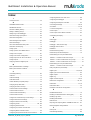
Contents
1
2
3
4
5
6
7
8
9
10
11
Page 4 of 188
Warnings & Cautions ...................................................................................................................... 8
1.1
Information to User ................................................................................................................ 8
1.2
Documentation Standards...................................................................................................... 8
1.3
Installation Notes ................................................................................................................... 8
Glossary & Symbols ....................................................................................................................... 9
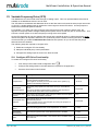
New Features in MultiSmart Version 2.1 ..................................................................................... 10
3.1
Screen changes ................................................................................................................... 10
3.2
New features........................................................................................................................ 10
Introduction ................................................................................................................................... 11
4.1
Range of Options ................................................................................................................. 11
4.2
Intuitive Operator Interface................................................................................................... 12
4.3
Intuitive Engineering Interface.............................................................................................. 12
4.4
"Out of the Box" Control of a Pump Station.......................................................................... 13
Operator Interface ......................................................................................................................... 13
5.1
LCD Display ......................................................................................................................... 14
5.2
LED Indicators ..................................................................................................................... 14
5.3
Buttons................................................................................................................................. 14
5.4
Using the Interface ............................................................................................................... 14
Mounting Instructions................................................................................................................... 25
6.1
Mounting the Operator Interface Display.............................................................................. 25
6.2
Mounting the Pump Controller ............................................................................................. 26
6.3
Connecting the Operator Interface to the Pump Station Manager ....................................... 26
MultiSmart Boards ........................................................................................................................ 27
7.1
Power Supply....................................................................................................................... 28
7.2
Default Wiring Setup for Pump Control Board...................................................................... 29
7.3
Pump Control Board............................................................................................................. 33
7.4
CPU Board........................................................................................................................... 38
7.5
DSP Board ........................................................................................................................... 39
7.6
Energy Monitoring & Motor Protection Board....................................................................... 46
PumpView Hardware Setup .......................................................................................................... 49
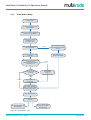
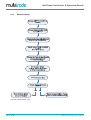
Quick Commissioning Guide ....................................................................................................... 51
9.1
Setup Wizard Flow Diagrams............................................................................................... 52
9.2
Setup Wizard Notes ............................................................................................................. 56
9.3
Unassign Any Faults Not Used ............................................................................................ 58
9.4
Level Simulation Mode......................................................................................................... 60
High Level Overview ..................................................................................................................... 61
10.1 MultiSmart Pump Station Manager Overview ...................................................................... 61
10.2 Pump Controller ................................................................................................................... 62
10.3 Reservoir Monitor................................................................................................................. 63
10.4 Pump Control Module .......................................................................................................... 64
10.5 Energy Monitoring and Motor Protection.............................................................................. 65
10.6 Supply Protection ................................................................................................................. 65
10.7 Data Logger ......................................................................................................................... 65
10.8 Flow ..................................................................................................................................... 65
10.9 Fault Module ........................................................................................................................ 66
10.10 Security ................................................................................................................................ 66
10.11 PLC Extension (IEC61131-3)............................................................................................... 66
10.12 Logic Engine ........................................................................................................................ 66
10.13 RTU...................................................................................................................................... 66
Security .......................................................................................................................................... 68
11.1 Selecting any Digital Tag ..................................................................................................... 70
MultiSmart_IO_Manual_A4_v2-1_R13.doc
MultiSmart Installation & Operation Manual
12
13
14
15
16
17
18
19
Fill / Empty & Pump Setpoints, Alarm Setpoints, Delays .......................................................... 72
12.1 Fill / Empty (Charge / Discharge) ......................................................................................... 72
12.2 Default Pump and Alarm Setpoints ...................................................................................... 72
12.3 Changing Pump and Alarm Levels Setpoints....................................................................... 73
12.4 Setting Pump & Alarm Delays.............................................................................................. 75
Pumps & Groups ........................................................................................................................... 77
13.1 Change Alternation & Fixed Duty......................................................................................... 78
13.2 Moving pumps between Groups, or Changing the order of Pumps...................................... 79
13.3 Adding or Deleting Groups & Changing Group Alternation .................................................. 80
13.4 Decommissioning Pumps..................................................................................................... 81
Configuring I/O, Fault & Level Devices ....................................................................................... 82
14.1 Digital Inputs ........................................................................................................................ 82
14.2 Assigning Faults to Digital Inputs ......................................................................................... 82
14.3 Unassigning Fault Inputs...................................................................................................... 83
14.4 Configuring General Purpose Digital Inputs ......................................................................... 84
14.5 Configuring Analog Inputs.................................................................................................... 87
14.6 Advanced Analog Input Options........................................................................................... 88
14.7 External Digital & Analog Modules ....................................................................................... 88
14.8 Configuring Level Devices ................................................................................................... 93
14.9 Configuring Faults .............................................................................................................. 102
14.10 Configuring Analog Outputs ............................................................................................... 106
14.11 Configuring Digital Outputs ................................................................................................ 107
14.12 Example: How To Make a Digital Output State Follow a Digital Input State....................... 109
Profiles ......................................................................................................................................... 110
15.1 Selecting Profiles with the User Interface........................................................................... 110
15.2 Selecting Profiles Using a Digital Input .............................................................................. 111
15.3 Selecting Profiles Using a Timer ........................................................................................ 111
15.4 Configuring the Setpoints of Profiles .................................................................................. 112
15.5 Configuring other Profile properties ................................................................................... 112
Station Optimization ................................................................................................................... 113
16.1 Station Optimization Menu ................................................................................................. 114
16.2 Odor Reduction.................................................................................................................. 114
16.3 Maximum Run Time ........................................................................................................... 115
16.4 Well Cleanout..................................................................................................................... 116
16.5 Well Washer....................................................................................................................... 116
16.6 Additional Parameters........................................................................................................ 116
16.7 Max. Number Groups Running .......................................................................................... 117
16.8 Group ................................................................................................................................. 117
16.9 Pulse Start & Pulse Stop.................................................................................................... 117
16.10 Well .................................................................................................................................... 117
Energy Monitoring and Motor Protection.................................................................................. 118
17.1 Setting Motor Protection Values......................................................................................... 118
17.2 Insulation Resistance Tester.............................................................................................. 120
17.3 Reassigning (Motor) Current Inputs used in Motor Protection ........................................... 124
17.4 Calculating Efficiency ......................................................................................................... 124
Supply Protection........................................................................................................................ 125
18.1 Configuring Faults .............................................................................................................. 126
Datalogger ................................................................................................................................... 126
19.1 Basis of Datalogging – Change of State and Deadbands .................................................. 127
19.2 Adding/Removing Tags from the Datalogger ..................................................................... 127
19.3 Filtering the Data Viewed in the History Page.................................................................... 128
19.4 Storing the Datalogger on the Compact Flash Card .......................................................... 128
19.5 Configuring the datalogger to write directly to a Compact Flash Card ............................... 129
19.6 Summary of Datalogger File Functions .............................................................................. 131
MultiSmart_IO_Manual_A4_v2-1_R13.doc
Page 5 of 188
MultiSmart Installation & Operation Manual
20
21
22
23
24
25
26
27
28
29
30
Page 6 of 188
Flow .............................................................................................................................................. 132
20.1 Configure General Flow Settings ....................................................................................... 132
20.2 Configuring Analog Inputs for Flow Measurement ............................................................. 133
20.3 Configuring Digital Inputs for Flow Measurement .............................................................. 133
20.4 Configuring Calculated Flow Settings ................................................................................ 133
20.5 Flow Alarms ....................................................................................................................... 134
20.6 Smart Outflow .................................................................................................................... 135
20.7 Estimating Duration to Overflow......................................................................................... 135
Reservoir Monitor........................................................................................................................ 137
21.1 Communications Configuration .......................................................................................... 137
21.2 User Interface .................................................................................................................... 138
21.3 Connection Manager.......................................................................................................... 139
RTU Module ................................................................................................................................. 141
22.1 Communications Screen .................................................................................................... 141
22.2 Communication Protocols .................................................................................................. 141
22.3 Enabling and Viewing of DNP and MODBUS Logs............................................................ 151
22.4 IP Address & Routing Settings........................................................................................... 151
22.5 Configuring PumpView & Cellular Communications .......................................................... 152
Variable Frequency Drive (VFD)................................................................................................. 154
23.1 Configure VFD Drive Functionality ..................................................................................... 154
23.2 Configure an Individual Pump’s VFD settings .................................................................... 155
23.3 Setup an Analog Output for use with a VFD Drive ............................................................. 155
23.4 Controlling a VFD Drive Using MODBUS........................................................................... 155
23.5 Displaying VFD speed on Main Screen.............................................................................. 155
PLC Extension IEC61131-3 (ISaGRAF) ...................................................................................... 156
24.1 Setting up the Workbench.................................................................................................. 157
24.2 Setting up I/O ..................................................................................................................... 157
24.3 MultiSmart Functions & I/O Blocks..................................................................................... 157
24.4 Downloading ISAGRAF Resources to MultiSmart ............................................................. 161
24.5 Compiling and Downloading Multiple Resources ............................................................... 161
24.6 Viewing the Status of ISaGRAF Variables ......................................................................... 162
24.7 The Tags Button ................................................................................................................ 162
24.8 The Params Button ............................................................................................................ 162
24.9 Backing UP ISaGRAF Recources ...................................................................................... 162
24.10 ISaGRAF Application Examples ........................................................................................ 163
Logic Engine................................................................................................................................ 164
25.1 MultiSmart Tags ................................................................................................................. 164
25.2 Logic Engine Tags ............................................................................................................. 165
25.3 Mathematical Operators..................................................................................................... 166
25.4 MultiSmart Logic Functions................................................................................................ 166
25.5 Advanced Functions........................................................................................................... 167
25.6 Logic Examples.................................................................................................................. 168
25.7 Uploading Logic Files Using FTP....................................................................................... 169
25.8 Enabling Logic Files ........................................................................................................... 170
Customizing the Display............................................................................................................. 171
26.1 Naming Pumps .................................................................................................................. 171
26.2 Pump Data Display ............................................................................................................ 172
26.3 Bottom Section................................................................................................................... 172
26.4 Invert Display ..................................................................................................................... 173
Restarting the MultiSmart........................................................................................................... 173
Site Keys and Enabling New Modules....................................................................................... 174
Upgrading MultiSmart Firmware ................................................................................................ 174
Backing Up & Restoring Configuration Settings...................................................................... 175
30.1 Resetting Defaults.............................................................................................................. 175
MultiSmart_IO_Manual_A4_v2-1_R13.doc
MultiSmart Installation & Operation Manual
31
32
33
34
35
30.2 Back Up Current Configuration .......................................................................................... 176
30.3 Restoring Backups ............................................................................................................. 176
More Advanced Configuration ................................................................................................... 177
31.1 Default Mode vs. Showing More Options ........................................................................... 177
31.2 Reference Manual.............................................................................................................. 177
Troubleshooting .......................................................................................................................... 178
32.1 There is no level displayed on my unit ............................................................................... 178
32.2 Every time the pump starts I see a Contactor Auxiliary fault .............................................. 178
32.3 My unit is showing a “Current Config Fail” fault.................................................................. 179
32.4 My unit has started with the message “Fail Safe Mode”..................................................... 179
32.5 PPP2 Manager Connection Error....................................................................................... 179
32.6 My unit keeps restarting ..................................................................................................... 179
Appendix A – Fault Message Glossary ..................................................................................... 180
Technical Specifications ............................................................................................................ 183
34.1 Processor Unit ................................................................................................................... 183
34.2 RTU/Communications ........................................................................................................ 183
34.3 Firmware/Application Upgrade Capability .......................................................................... 183
34.4 I/O Standard Modules ........................................................................................................ 183
34.5 I/O-3MP: Motor Protection I/O Board ................................................................................. 183
34.6 Power (per unit) ................................................................................................................. 183
34.7 Power Supply & Environmental.......................................................................................... 183
34.8 Product Dimensions ........................................................................................................... 183
MultiTrode Terms & Conditions of Sale .................................................................................... 184
MultiSmart_IO_Manual_A4_v2-1_R13.doc
Page 7 of 188
MultiSmart Installation & Operation Manual
1
Warnings & Cautions
1.1
Information to User
Read through this manual to obtain a good working knowledge in order to get maximum performance from
the product for your application. After reading, put the manual away in a safe place for future reference.
1.2
Documentation Standards
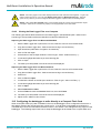
DANGER:
THIS SYMBOL IS USED WHERE NON-COMPLIANCE COULD RESULT IN INJURY OR DEATH.
WARNING:
THIS SYMBOL IS USED WHERE NON-COMPLIANCE COULD RESULT IN INCORRECT
OPERATION, DAMAGE TO OR FAILURE OF THE EQUIPMENT.
NOTE:
THIS SYMBOL IS USED TO HIGHLIGHT AN ISSUE OR SPECIAL CASE WITHIN THE BODY OF
THE MANUAL.
1.3
Installation Notes
WARNING:
THE MULTISMART INSTALLATION AND WIRING MUST BE PERFORMED BY QUALIFIED
PERSONNEL.
DANGER:
THE MULTISMART HAS NO USER SERVICEABLE PARTS. TO REDUCE THE RISK OF
ELECTRIC SHOCK, LEAVE ALL SERVICING TO QUALIFIED MULTITRODE TECHNICAL STAFF.
DANGER:
INSTALLATION OR USE OF THIS EQUIPMENT OTHER THAN IN ACCORDANCE WITH THE
MANUFACTURERS INSTRUCTIONS MAY RESULT IN EXPOSURE TO HARM, SERIOUS INJURY
OR DEATH.
Page 8 of 188
MultiSmart_IO_Manual_A4_v2-1_R13.doc
MultiSmart Installation & Operation Manual
2
Glossary & Symbols
Activation Level
The point at which a pump or alarm is switched On.
Alternate Mode
The pump controller automatically switches the lead (duty) pump each cycle.
Deactivation Level
The point at which a pump or alarm is switched Off.
Decommissioned Pump
A pump that has been removed from duty or an installation, e.g. for maintenance
purposes.
Duty (Lead) Pump
The main pump or the first pump to start within a pumping cycle.
Empty (Discharge) Mode
When the pump controller is set to empty a tank or pit.
Fill (Charge) Mode
When the pump controller is set to fill a tank or pit.
Fixed Sequence
Pump 1 or pump 2 is fixed as the lead (duty) pump.
InterPump Start Delay
The delay between any two pumps starting.
InterPump Stop Delay
The delay between any two pumps stopping.
Probe
MultiTrode manufactures a range of conductive level sensors. They have many
advantages over traditional devices such as ball floats. Advantages include:
resistance to fatty deposit build-up, tangle-free and an adjustable sensitivity to liquid
to prevent false readings.
Standby (Lag) Pump
The secondary pump or the next pump to start within a pumping cycle.
ISaGRAF
ISaGRAF is a control software environment which supports all of the internationally
recognised IEC61131-3 control languages and offers a combination of highly
portable and robust control engine.
Ω
Resistance Value (Ohm)
EMC
Electromagnetic Compatibility
Hz
Frequency (Hertz)
LED
Light Emitting Diode
MTU
Master Terminal Unit
N/O
Normally Open
N/C
Normally Closed
RTU
Remote Telemetry Unit
VAC
Alternating Current Voltage
VDC
Direct Current Voltage
MultiSmart_IO_Manual_A4_v2-1_R13.doc
Page 9 of 188
MultiSmart Installation & Operation Manual
3
New Features in MultiSmart Version 2.1
3.1
Screen changes
•
Ability to view MODBUS and DNP3 logs in Info screens
•
Ability to view in the Communication overview in Settings screens
•
Ability to invert the display screen
3.2
New features
•
Duo Probe Support
•
Remote reconfiguration of DNP points list
•
I2T Motor protection
•
Support for Acromag external I/O devices
•
Multiple sources can be assigned to the Digital Outputs
•
Ability to enable and disable DNP and MODBUS logging via MultiSmart faceplate
•
Superior flow calculation with ability to differentiate blocked pump from a large inflow
•
Ability to compare two analog input levels and raise alarm if they differ by more than a specified
percentage
•
Advanced level locked detection
•
Support for multiple thresholds for Insulation Resistance Test
•
Capability to calculate the time period until the station starts spilling
•
Automatic DSP upgrade along with the main software update
Page 10 of 188
MultiSmart_IO_Manual_A4_v2-1_R13.doc
MultiSmart Installation & Operation Manual
Part 1 – Operations
4
Introduction
Congratulations on your purchase of the MultiTrode MultiSmart unit.
Depending on the options you have purchased, the unit may be configurable as either a pump controller or a
reservoir monitor or as a Remote Telemetry Unit. The generic product description of MultiSmart pump
manager is used throughout the manual and for convenience refers to either configuration.
The pump station manager is an "out of the box" pump controller for water and sewerage pump stations.
The large LCD screen with softkeys eliminates the need for selector switches, push buttons, fault lights,
meters, accumulators and other additional panel items. This simplifies panel wiring and reduces cost.
The product has a very low “whole of life” cost compared with a PLC due to the pump control functionality
already developed in the product. Users simply configure the parameters, rather than program the unit.
This reduces engineering cost and greatly increases reliability.
The MultiSmart pump station manager has the option of an IEC61131-3 PLC programming language so that
additional functionality can be added by the user if required.
The MultiSmart unit is fully open and has DNP3 and Modbus options. The product can also be shipped just
as an RTU without any pump control functionality or user interface.
The Reservoir Monitor is a version of the product for monitoring reservoirs and communicating with remote
pump stations.
4.1
Range of Options
The functionality of the basic product can be enhanced with additional software modules:
•
DNP3 RTU with Security
•
Modbus protocols (RTU, TCP, ASCII) - standard feature in some markets
•
Flow calculations for “Empty (Discharge)” applications – no flow meter required
•
VFD control
•
“Energy Monitoring and Motor protection” option which allows power, energy, power factor and
pump efficiency monitoring as well as 3-phase currents, motor protection functions and insulation
resistance tests (requires energy monitoring and motor protection I/O module)
•
Logic engine (for custom logic additions)
•
ISaGRAF 5 IEC61131-3 PLC programming
The unit can be shipped with these modules enabled, or they can be enabled in the field with the appropriate
enable code. Additional I/O boards can be installed in the factory to allow expansion of I/O as well as motor
protection options.
MultiSmart_IO_Manual_A4_v2-1_R13.doc
Page 11 of 188
MultiSmart Installation & Operation Manual
4.2
Intuitive Operator Interface
The product has screens which have been designed for operators of pump stations. The operator can see at
a glance:
•
Level
•
Pump mode
•
Pump availability
•
Detailed fault information
•
Date/time of each fault occurring and clearing
•
Single or 3-phase supply, D.C supply
•
History (50,000 events)
•
Accumulators (starts, hours, faults, etc)
•
Pump efficiency (requires energy monitoring, motor protection and flow enabled)
•
Status of all I/O
•
Status of the communication link
The screen also allows easy control of pumps and resetting of faults.
4.3
Intuitive Engineering Interface
The product has clear menu screens for altering:
•
Pump setpoints
•
Alarm setpoints
•
Delays
•
Alternation and grouping
•
Level device and backup level device
•
Number of pumps
•
I/O and fault configuration
•
Supply protection
•
Energy Monitoring and Motor protection (where installed)
•
Station optimization parameters (max run time, max off time, max starts per hour, plus many more)
•
Data logging parameters
•
Communications
•
Profiles
Page 12 of 188
MultiSmart_IO_Manual_A4_v2-1_R13.doc
MultiSmart Installation & Operation Manual
4.4
"Out of the Box" Control of a Pump Station
The I/O unit clips onto DIN rail and has plug in terminal blocks. When the unit is powered ON for the first
time, the controller will start with a setup wizard, which will generate a basic pump station controller
configuration by taking input from the user. The basic configuration will take into account of the MultiTrode
probes and other level devices, Fill/Empty application, number of pumps, number of wells, station power
supply and DNP communication settings.
Even though the basic setup meets most of the normal pump station requirements, with a few button presses
the MultiSmart can be setup to perform most of the complex pump station management requirements.
Changing between a reservoir and a pump station, changing the level device to a 4-20mA (e.g. ultrasonic or
pressure transducer), the number of pumps, the number of wells, or Empty (Discharge) to Fill (Charge) is
done through the setup wizard or through the settings menu and takes only a few minutes, which is far less
than time required to implement the same functionality using a standard PLC.
Complete station setups can be saved and/or loaded via a compact flash card.
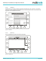
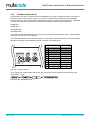
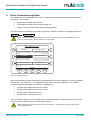
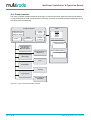
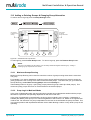
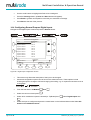
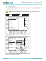
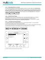
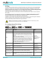
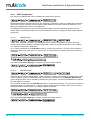
5
Operator Interface
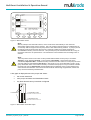
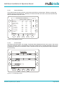
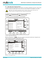
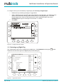
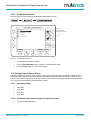
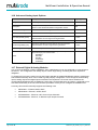
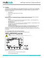
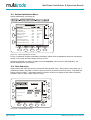
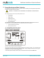
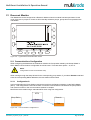
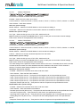
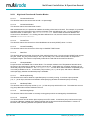
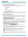
The MultiSmart Pump Controller has an easy to use interface featuring a large graphical LCD display. A
large amount of information can be displayed on the screen making it simple for an operator to determine the
current status at a glance. The buttons around the edge of the screen are used to access features depending
on what is displayed at the time.
Pump1
RUNNING
55.0%
1
2
3
abc
def
ESC
Manual AVAILABLE
4
Off
AUTO
ghi
Last Run 9 mins
Pump2
7
pqrs
NEXT TO RUN
Manual AVAILABLE
6
5
jkl
mno
8
9
tuv
wxyz
0
OFF
AUTO
Last Run 5 mins
3
Date:
15 Feb 2009, 09:21:22
Supply: AB:416.6V, BC:420.2V, CA418.7V
Mode: Empty - Profile: Default
1
Settings
Info
History
4
Faults
2
5
6
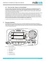
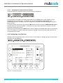
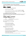
Figure 1 - MultiSmart Display
1. Fault Indication LED
2. Power Status LED
3. Home Button
4. Help Button
5. Increase Contrast
6. Decrease Contrast
MultiSmart_IO_Manual_A4_v2-1_R13.doc
Page 13 of 188
MultiSmart Installation & Operation Manual
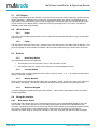
5.1
LCD Display
The large LCD display gives the operator a clear view of how the pump station is operating. Water levels are
shown graphically. A backlight turns on when any of the panel buttons are pushed. The backlight turns off
again after a set time of inactivity (time is user configurable). The display method is invertible as well, that is,
we can set the LCD to display data in a dark colour with a light background or vice versa. This feature is
especially good under bright sunlight.
5.2
LED Indicators
5.2.1
Power
The Power LED is at the bottom left hand corner of the panel and indicates that the DC supply is connected
and turned on.
5.2.2
Faults
The fault LED is above the power LED. It flashes once a second when a pump station fault is detected. This
gives the operator a quick indication of whether a fault is present without having to access the LCD screen.
5.3
Buttons
5.3.1
Home/Help Button
The Home/Help button has two positions:
•
Pressing the home icon returns the user to the main status screen.
•
Pressing the Help icon displays online help for the currently displayed screen.
5.3.2
Contrast Button
The contrast button is used to adjust the LCD screen’s contrast. Press “+” or “–“ as required to optimise the
display for the light conditions.
5.3.3
Display Buttons
Eleven buttons are located around the edge of the LCD display. These are used to access menu items and
other data on the display. The display will indicate what each button is used for on a particular screen.
5.3.4
Numerical Keypad
A numerical keypad is located at the right of the interface. This is used to enter alpha-numeric characters
during configuration.
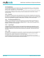
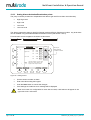
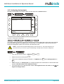
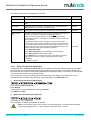
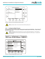
5.4
5.4.1
Using the Interface
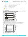
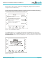
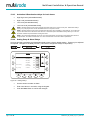
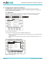
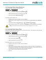
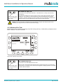
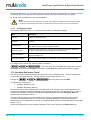
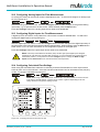
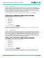
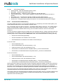
Main Status Screen
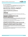
Pressing the Home button turns on the LCD backlight and also returns the MultiSmart display to the main
status screen. This screen displays the current status of all pumps connected to the MultiSmart Pump
Controller. The buttons located next to each pump can be used to switch the pump between Manual (Hand),
Off, or Auto. The Off mode can be disabled from the advanced menu if need be, to meet security
requirements. While doing so if the pump is already in Off mode, it will stay Off until the mode is changed.
Page 14 of 188
MultiSmart_IO_Manual_A4_v2-1_R13.doc
MultiSmart Installation & Operation Manual
Pump1
RUNNING
55.0%
Manual AVAILABLE
Off
Auto
Last Run: 9 mins
Pump2
NEXT TO RUN
Manual AVAILABLE
Off
Auto
Last Run: 5 mins
Date:
15 Feb 2009, 09:21:22
Supply: AB:416.6V, BC:420.2V, CA:418.7V
Mode: Empty - Profile: Default
Settings
Info
History
Faults
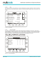
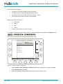
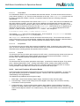
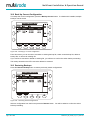
Figure 2 - Main Status Screen
Note:
Manual (Hand) is semi-automatic manual, as the mode returns automatically to Auto when the
deactivation setpoint of the pump is reached. This is to prevent pumps being left on unintentionally as
occasionally staff can forget to turn the pumps back to Auto before leaving a station. A pump is put into
full manual mode as follows: when the pump is in Off mode, instead of just briefly pressing the
Auto/Off/Manual button, press and hold it in. This puts the pump into Full Manual mode for as long as
the button continues to be pressed down. The Off selection can be disabled from the settings menu if
needed.
Note:
The Pump status shown in the screen for the possible different states of each pump is as follows.
Stopped – Pump Stopped, Running – Pump Running, Unavailable – Fault present and hence
unavailable, Request to Run – Contactor Auxiliary is wired in and the control to run the pump has been
sent and waiting for the feedback, Next to Run – Next pump to run in pump alternation mode or pump
group alternation mode. If the contactor auxiliary is used and if the pump is run by an external controller
the status will now say External Run and the MultiSmart will update the pump run time statistics and
other relevant historical data. In this mode the relevant faults and warning are generated, however the
pump will not be faulted by the MultiSmart.
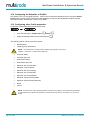
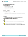
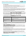
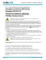
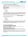
A bar graph is displayed next to the pumps and shows:
•
the current water level
•
each pump’s activation and deactivation levels
•
any level alarms that may have been configured
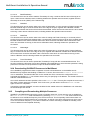
55.0%
Level Alarms
Lag (Standby) Pump
activation and deactivation levels
Lead (Duty) Pump
activation and deactivation levels
Figure 3 - Main Status Screen Bar Graph
MultiSmart_IO_Manual_A4_v2-1_R13.doc
Page 15 of 188
MultiSmart Installation & Operation Manual
The buttons at the bottom of the screen are used to access the following areas:
•
Settings:
Used to configure the MultiSmart pump station manager
•
Info:
Displays full station and pump information
•
History:
Shows alarms and event history
•
Faults:
Shows fault specific details
Note:
when the unit is controlling more than 4-pumps, a Next Pumps button also appears, which allows
access to pumps 5, 6, etc.
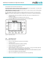
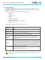
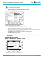
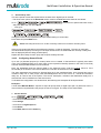
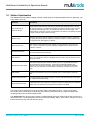
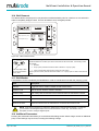
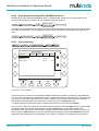
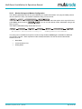
5.4.2
Faults / History
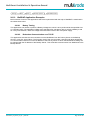
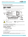
When a fault occurs, the LCD screen will display a large FAULT box at the bottom of the screen. The pump
with the fault present (if the fault is pump related), will also be indicated.
Pump1
STOPPED
55.0%
Manual UNAVAILABLE
Off
FAULT PRESENT
Auto
Last Run: 9 mins
Pump2
NEXT TO RUN
Manual AVAILABLE
Off
Auto
Last Run: 5 mins
Date:
15 Feb 2009, 09:21:22
Supply: AB: 416.6V, BC: 420.2V, CA: 418.7V
Mode: Empty - Profile: Default
FAULT
Settings
Info
History
Faults
Fault
Menu
Button
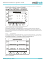
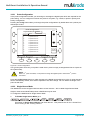
Figure 4 - Fault Indication
The Fault menu button will flash when a fault is present. Pushing this button will take the operator to a
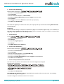
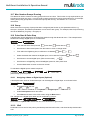
screen which details the exact fault (a detailed description of all faults is found in Appendix A).
Fault Name
Mute
Fault
Reset
Fault
Status
Thermal Fault on Pump 1
Reset Required
Seal Fault on Pump 2
Present
Selector
Buttons
Fault Triggered @ 15/02/2009 00:39:59
Fault Cleared @ 15/02/2009 00:40:48
Reset required to deactivate fault.
Press ‘Reset Fault’ to deactivate.
Devices Affected: Pump 1
Main
History
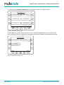
Figure 5 - Fault Reset Screen
Page 16 of 188
MultiSmart_IO_Manual_A4_v2-1_R13.doc
MultiSmart Installation & Operation Manual
Use the selector arrows to select each fault in turn.
From this screen the operator can reset the fault if the fault condition is no longer present. If the fault is still
present the operator will be told that they cannot reset the fault.
A Mute Fault button will appear for faults that can be muted. It is used to stop any sirens or flashing lights
that may have been activated by the fault.
By default, digital output 4 (DO4) is linked to the high-level alarm and can be muted. The output can be
configured for Pulsed or Steady operation and is designed to be connected to an external warning light or
alarm.
•
The mute button will only be available for other faults if the user has configured them to be
available for muting.
•
Pressing the History button will display the entire history log.
•
Pressing the Main button returns the operator to the main status screen.
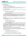
Alarm & Event History
Event
Value
AIN 1
50.0000
Date/Time
00:50:23 06 Feb 2009
AIN 2
60.9750
22:15:13 05 Feb 2009
Temperature
34.5
22:14:44 05 Feb 2009
Current Level (scaled)
0.0000
22:14:39 05 Feb 2009
Pump2 Running
False
22:14:39 05 Feb 2009
Pump1 Running
False
22:14:25 05 Feb 2009
Pump2 Flow Rate
0
22:14:15 05 Feb 2009
Pump1 Flow Rate
0
22:14:05 05 Feb 2009
Inflow Rate
0.0
21:59:03 05 Feb 2009
Overflow
False
21:37:56:21 Feb 2009
Back
PgUp
PgDn
Filters
Refresh
Delete
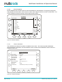
Figure 6 – Fault History Screen
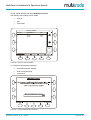
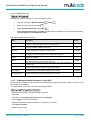
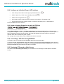
5.4.3
Information Screen
The Information screens show:
•
Hours run, starts and faults for each pump and the station
•
The status of all I/O
•
Flow data (when the optional flow module is installed)
•
System log (identifies any application problems)
•
Version and modules installed in the unit
•
Power and Efficiency – kW, kVA, power factor, pump efficiency, energy accumulators (kWh and
kVAh) for various periods: today/yesterday; this week/last week
•
Communications statistics for DNP3/MODBUS slave and the current DNP3 Modbus tag values1
•
Option to browse MultiSmart internal tag database2
•
Option to view ISaGRAF 5 tags and values useful for PLC programming
MultiSmart_IO_Manual_A4_v2-1_R13.doc
Page 17 of 188
MultiSmart Installation & Operation Manual
To navigate to the Information Screen press the Info button on the main operator screen.
Information: P1 of 2
Pump Information
I/O Information
Pump Runtime, Start and Fault information
I/O Module Statistics
Power & Efficiency
Power, power factor, and pump efficiency
Communications
Display DNP and Modbus communication
statistics.
Flow
Browse Database
Inflow, pump outflow, and volumes pumped
Navigate to and view values and statistics
of all nodes and tags in the database
Main
More ...
Figure 7 - Information Screen 1of 2
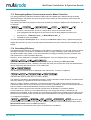
Pressing More brings you to the second screen which includes the Version button to give details on the
version installed on the unit. Note that free upgrades of firmware are available on the MultiTrode web site.
Information: P2 of 2
Version Information
Version and Module Information
System Log
View messages from the system hardware
and software.
ISaGRAF 5
View resource name, download time, cycle
count, and status of ISaGRAF variables.
Main
More ...
Figure 8 - Information Screen2 of 2
Page 18 of 188
MultiSmart_IO_Manual_A4_v2-1_R13.doc
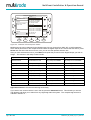
MultiSmart Installation & Operation Manual
5.4.3.1
Power & Efficiency
This screen shows the value of power, power factor and efficiency of the pumps. Efficiency, energy and
apparent energy of the present day, yesterday, this week, last week, this month, last month and their total
can be observed through this screen.
Calc Pump Power and Efficiency
Pump 1 Pump 2 Pump 3
Power (kw)
11.2
10.9
0.0
Power Factor
0.86
0.85
0.00
13.1
12.9
0.0
Apparent Power
Scroll
Efficiency (L/kW):
. . Today
6530
6108
0
. . Yesterday
6540
6045
0
. . This Week
6535
6197
0
. . Last Week
6600
6133
0
. . This Month
6590
6084
0
. . Last Month
6821
6085
0
. . Total
6623
6105
0
Back
Set
Reset
Figure 9 - Power Efficiency Screen
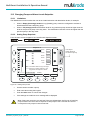
5.4.3.2
I/O Information
Information about the System, DC Voltage, Top Board, Bottom Board and Probe can be seen in this screen.
These are especially useful in troubleshooting input/output related issues. Insulation Resistance test can be
accessed from within the I/O information screen. However the test can only be performed when the pumps
are not running.
I/O Information
Figure 10 – I/O Information Screen
MultiSmart_IO_Manual_A4_v2-1_R13.doc
Page 19 of 188
MultiSmart Installation & Operation Manual
5.4.3.3
Flow
The station inflow rate, pump outflow rate, volume pumped during a range of intervals, number of overflows,
last over flow time, last overflow duration, duration to overflow and total overflow volume can be seen in this
screen.
Flow Statistics
Rate
Select
Value
Station Inflow Rate
Pump 1 Outflow Rate
Pump 2 Outflow Rate
45 gals/min
912 gals/min
930 gals/min
Volume Pumped Today
Volume Pumped Yesterday
Volume Pumped This Week
volume Pumped Last Week
Total volume Pumped
Number of Overflows
Last Overflow Time
Total Overflow Volume
Back
98328 gals
131359 gals
409743 gals
840697 gals
63052320 gals
1
15:13:05 24 Mar 2006
5407 gals
PgUp
PgDn
Set
Reset
Figure 11 - Flow Screen
5.4.3.4
Pump Information
The station, pump and generator runtime, start and fault statics is displayed in this screen. In the case of
runtime statistics, if Pump1 is running for 1 hour by itself, Pump 2 is running for 1 hour by itself and if both of
them are running for 1 hour together then Pump 1 and Pump2 runtimes will be 2 hours each where as the
Station runtime will be 3 hours since both the pumps were running together for an hour.
Pump Information: Starts
Station Generator
Pump 1
Pump 2
Starts This Hour
Starts Last Hour
Starts Today
Starts Yesterday
0
0
*0
0
0
0
*0
0
0
0
*0
0
0
0
*0
0
Starts This Week
Starts Last Week
Total Starts
*0
0
0
*0
0
0
*0
0
0
*0
0
0
* = Data is suspect due to device reset or date/time modification
Back
Set
Reset
Figure 12 – Pump Start Statistics
Page 20 of 188
MultiSmart_IO_Manual_A4_v2-1_R13.doc
MultiSmart Installation & Operation Manual
For the Generator runtime statistics to be calculated; a digital input needs to be wired in to the MultiSmart
and that should be configured to the generator running fault.
Pump Information: Run Time
Station Generator
Pump 1
Pump 2
Last (mins)
This hour (mins)
Last Hour (mins)
Today (hrs)
2.5
9.7
10.1
1.3
6.2
15.4
14.4
1.5
3.4
0.0
0.0
0.0
0.0
0.0
5.2
0.0
Yesterday (hrs)
This Week (hrs)
Last Week (hrs)
Multiple (hrs)
Total (hrs)
*1.2
*4.6
4.7
*1.4
*4.7
2.1
0.0
0.4
2.4
1.4
1.5
0.4
1045.3
1288.1
621.0
1.9
* = Data is suspect due to device reset or date/time modification
Set
Back
Reset
Figure 13 – Pump Information Screen for a 3-pump station
The insulation resistance test can be triggered from the corresponding menu in the Pump Information
section. The result of the test and the related values can also be observed in this screen. The test can be
performed only when the pump is not running. Insulation Resistance test can also be accessed from the I/O
information screen.
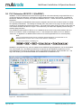
5.4.3.5
Communications
The DNP and MODBUS master and slave status and values can be seen from this menu. Viewing the tag
values real-time will help in troubleshooting any communication errors. If logging is enabled then we could
see the logged events related to communication in this menu by selecting View Log.
Communications Information
DNP Slave Stats
DNP Slave Statistics and Diagnostics
Modbus Slave Stats
Modbus Slave Statistics and Diagnostics
DNP Master Stats
DNP Master Statistics and Diagnostics
Back
DNP Slave Values
Display values of DNP Slave Points
Modbus Slave Values
Display values of Modbus Slave Points
DNP Master Values
Display values of DNP Master Points
View Log
Figure 14 –Communications
MultiSmart_IO_Manual_A4_v2-1_R13.doc
Page 21 of 188
MultiSmart Installation & Operation Manual
5.4.3.6
Browse Database
Browse database lists all nodes within the real-time database on the MultiSmart. The tags are categorized
and grouped into these nodes. Each node can contain a list of tags as well as a number of child nodes. This
screen enables the real-time viewing of all the tags and their values.
View Nodes
Select
Node Name
+.....ACROMAG
+.....ADAM
+.....Calc Stats
+.....Config
+.....Conmng
+.....DNP Master
+.....DNP Slave
+.....Event Logger
+ /-
+.....Faults
+.....Flow
+
Back
PgUp
Tags
PgDn
Figure 15 –Browse Database
5.4.3.7
Version Information
The hardware and software information is available in this screen. This must be quoted if MultiSmart
technical support is requested. The DSP Software Version number and the MultiSmart serial number are
available in this menu.
Version Information
Value
DSP VERSION
SERIAL NUMBER
BUILD VERSION
BUILD REVISION
BUILD DATE
BUILD USER
BUILD HOST NAME
BUILD GRADE
BUILD NO
HW REVISION
0.2.00.0rel0
C094568
2.1.0
01
16/03/2009 13:56:45
scottm
buildm.multitrode.com.au
rel
000286
PCB400001r01(Full serial port + DuoProbe)
Back
Modules
Figure 16 –Version Information
Page 22 of 188
MultiSmart_IO_Manual_A4_v2-1_R13.doc
MultiSmart Installation & Operation Manual
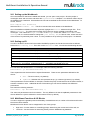
5.4.3.8
ISaGRAF 5
ISaGRAF resource information including compile data, download rate, mode, cycle time, cycle overflow,
cycle count, and tags, parameters and variables can be viewed through this screen. Also the value of the
parameters can be changed from this menu.
ISaGRAF 5 Info - Resource Number 1
Resource Name
1 1970, 00:00:00
Compile Date
Download Date
Mode
No resource available
Cycle Time (ms)
0
Cycle Overflows
0
Cycle Count
0
Tags
Back
Params
Variables
Figure 17 –ISaGRAF
5.4.3.9
System Log
System Log displays any system errors with the time stamp.
System Log
Date/Time
Event
Value
11:4 1:3 7 03/19/200 9 System
Ena ble co de se t to ”05BA D”
08:42:18 03/10/2009 IO Mo dule
CAN ID:0 .Incorrect IO Board
Back
PgUp
Select
PgDn
Figure 18 –System Log
MultiSmart_IO_Manual_A4_v2-1_R13.doc
Page 23 of 188
MultiSmart Installation & Operation Manual
5.4.4
Settings Screen
Changes to the operation of the MultiSmart unit can be done by accessing this menu. Most of the general
pump station requirements can be configured from the sub sections under Settings. However a wide range
of advanced configuration options are also available which could be accessed and configured through the
Advaced button in the Settings menu.
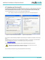
Some of the settings require a reboot of the MultiSmart unit for it to come into effect after the change, where
as a few others will come into effect as soon as the changes are saved. If a restart is required MultiSmart
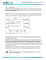
prompts the user with three options, Restart Now, Restart Later and Continue as shown the figure below.
Warning:
The changes you have made will not take effect
until the unit is restarted.
If you need to make other changes, then you should
choose the Continue option, and ensure that you
restart the unit when all of your configuration
changes are complete.
Restart Now
Restart Later
If this is your only change or last change, then you
should choose the Restart Now option.
Continue
Figure 19 –Warning Screen
If Restart Now is selected the unit will save the current values and reboot immediately before any further
configuration changes can be performed. If we need to do several configuration changes, we could either
choose Restart Later or Continue.
If Restart Later is selected the MultiSmart will resume normal operation, however the new changes will not
be in effect. If this option is selected once, the restart prompt will be disabled until the next reboot of the unit
and all the configuration changes will be saved in the unit. This can save some time to the operator while
making several changes together which requires a reboot. The Restart Later need to be selected when
prompted after the first change which requires rebooting, and this prompt will not come up even if all or some
of the subsequent changes requires a reboot. However in the main screen a fault, which will be cleared only
after a reboot, appears in the main screen, as an obvious reminder, mentioning that a restart is necessary for
the new changes to be in effect.
The Continue option is similar, that it also prevents an immediate reboot of the unit, but a restart will be
prompted for every subsequent change in the configuration. There are no other faults or indicators in the
MultiSmart which will point out to the user that the new changes are not in effect if this option is selected.
Note:
The restart option does not work like this always. For some major changes like adding a new DNP slave
profile, the MultiSmart will ignore the restart option selected and does an immediate reboot to bring the
new changes into immediate effect.
Page 24 of 188
MultiSmart_IO_Manual_A4_v2-1_R13.doc
MultiSmart Installation & Operation Manual
Part 2 – Installation & Commissioning
6
Mounting Instructions
The MultiSmart pump station manager is mounted on a standard DIN rail inside a panel. The operator
interface is usually mounted on the outside of the panel. The two units are connected together with a
supplied cable.
6.1
Mounting the Operator Interface Display
The operator interface is mounted to the switchboard panel with 8 x M4 hex head screws. A 20mm hole
must also be cut to accommodate the cable connecting the interface to the controller. Drilling dimensions
are given below.
Figure 20 - Mounting the Display
MultiSmart_IO_Manual_A4_v2-1_R13.doc
Page 25 of 188
MultiSmart Installation & Operation Manual
6.2
Mounting the Pump Controller
The pump station manager is designed to mount onto 35mm DIN rail. Overall dimensions are given below.
Figure 21 - Mounting the Controller
6.3
Connecting the Operator Interface to the Pump Station Manager
The interface and pump station manager are connected together with a supplied cable. Connect one end
into the RJ45 socket on the back of the interface. Connect the other end into the RJ45 socket marked
DISPLAY on the MultiSmart CPU Board.
Figure 22 - Connecting the display interface
Page 26 of 188
MultiSmart_IO_Manual_A4_v2-1_R13.doc
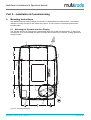
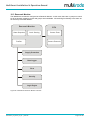
MultiSmart Installation & Operation Manual
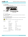
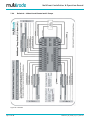
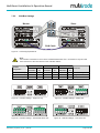
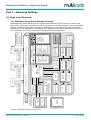
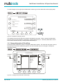
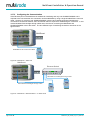
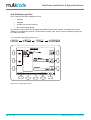
7 MultiSmart Boards
The MultiSmart pump station manager has up to four boards plugged into it depending on the application.
The most common configuration is shown below.
Pump Control I/O Board (3PC) - The pump control board monitors the single or 3-phase supply and
provides digital and analog I/O. Level sensing can be from a MultiTrode conductive probe or any 4-20mA
device (e.g., pressure transducer, ultrasonic device). Pump faults can be contact closures or pump specific
inputs such as seal, PTC thermistor or Flygt FLS and CLS. Digital outputs drive the pump contactors. (I/O =
20 x DIN, 2 x AIN, 7 x DOUT, 1 x AOUT)
CPU Board - Houses the microprocessor running the MultiSmart unit, provides serial and Ethernet
communications ports, connects to the display, and has an optional compact flash card port.
WARNING:
BEFORE REMOVING THE COMPACT FLASH CARD, YOU MUST PRESS THE YELLOW SAVE CF DATA
BUTTON. FAILURE TO DO SO MAY CAUSE CORRUPTION OF DATA OR DAMAGE TO THE FLASH CARD.
WARNING:
THE DIGITAL INPUTS ARE VOLT-FREE INPUTS. DO NOT APPLY ANY SOURCING VOLTAGE TO THEM.
DSP Board
This board handles the IO and communicates between multiple IO Module modules.
Energy Monitoring and Motor Protection (3MP)
Monitors single or 3-phase motor currents direct from a CT, and provides motor protection, power
monitoring, and includes datalogging. The board also carries out an automatic 1000v insulation resistance
test of the motor windings (I/O = 9 x IIN, 3 x IRT, 3 x AOUT, 5 x DOUT).
Figure 23 – MultiSmart Boards
MultiSmart_IO_Manual_A4_v2-1_R13.doc
Page 27 of 188
MultiSmart Installation & Operation Manual
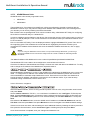
7.1
Power Supply
The MultiSmart pump station manager runs from an external 12 – 24 VDC (+/- 5%). This external DC supply
is connected into the DSP board as shown below:
Figure 24 - Power Supply
7.1.1
Power Consumption
The MultiSmart unit consumes up to 30W per unit during initial start-up, (inrush current), and 15W per unit
during continuous operation.
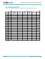
7.1.2
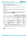
Power Supply Requirements
The product must be used in conjunction with a power supply that meets or exceeds the specifications listed
in Table 1 - Power Supply Specifications.
NOTE:
To maintain UL compliance of the product, the power supply must also be UL Listed.
OUTPUT
INPUT
ENVIRONMENT
DC Voltage
12 – 24 VDC
Power
>30W
Voltage Tolerance
+ - 2.0%
Line Regulation
+ - 0.5%
Load Regulation
+ - 0.5%
Voltage Range
85 ~ 264VAC (120~370VDC)
Frequency Range
47-63Hz
Working Temp
-10°C ~ +60°C
Working Humidity
20-90% RH non-condensing
Storage Temp/ Humidity
-20°C~ +85°C, (10~95RH)
Table 1 - Power Supply Specifications
Page 28 of 188
MultiSmart_IO_Manual_A4_v2-1_R13.doc
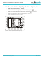
MultiSmart Installation & Operation Manual
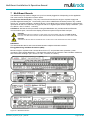
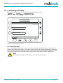
7.2
Default Wiring Setup for Pump Control Board
The Pump Control Board has 4 different default configurations which can be used to simplify setup. These
default configurations can be applied by completing the “Setup Wizard” in the Settings Menu. After a default
configuration has been applied changes can be made as required. Refer to Section 7.3 for a complete
description of the Pump Control Board I/O interface.
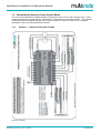
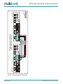
7.2.1
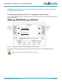
Default 1 – 10 Sensor Probe and 2 Pumps
Figure 25 - Default 1
MultiSmart_IO_Manual_A4_v2-1_R13.doc
Page 29 of 188
MultiSmart Installation & Operation Manual
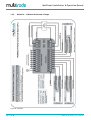
7.2.2
Default 2 – 10 Sensor Probe and 3 Pumps
Figure 26 - Default 2
Page 30 of 188
MultiSmart_IO_Manual_A4_v2-1_R13.doc
MultiSmart Installation & Operation Manual
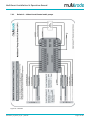
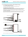
7.2.3
Default 3 – 4-20mA Level/Control and 2 pumps
Figure 27 - Default 3
MultiSmart_IO_Manual_A4_v2-1_R13.doc
Page 31 of 188
MultiSmart Installation & Operation Manual
7.2.4
Default 4 – 4-20mA Level/Control and 3 Pumps
Figure 28 - Default 4
Page 32 of 188
MultiSmart_IO_Manual_A4_v2-1_R13.doc
MultiSmart Installation & Operation Manual
7.2.5
Contactor Auxiliary Fault
If the contactor auxiliary is wired, there is a slight difference in the LCD status display for pump running. If the
contactor auxiliary wiring is not present, which is used to get the feedback of pump running status, as soon
as the pump running command is sent, MultiSmart will display the status of the pump as Running. However
if contactor auxiliary is wired, MultiSmart will display Request to Run after issuing the command to run the
pump, and when the contactor is closed the status will be updated as Running.
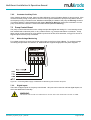
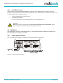
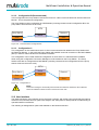
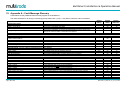
7.3
Pump Control Board
The pump control board monitors mains voltage and provides digital and analog I/O. Level sensing can be
from a MultiTrode conductive probe, or any 4-20mA device, e.g. pressure transducer or ultrasonic. Pump
faults can be contact closures or pump specific inputs such as seal, PTC thermistor, or Flygt FLS and CLS.
Digital outputs drive the pump contactors.
7.3.1
Mains Voltage Monitoring
For voltage monitoring to work connect the main supply to the Pump Control Board. To configure voltage
monitoring and protection see Section 18. MultiSmart also supports single phase AC power supplies.
Figure 29 – Connecting Mains Supply to MultiSmart for Monitoring and Protection Purposes.
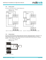
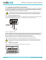
7.3.2
Digital Inputs
There are 20 digital inputs on the pump control board. All inputs can be used as volt-free digital inputs, but
also have additional functionality:
WARNING:
THE DIGITAL INPUTS ARE VOLT-FREE INPUTS. DO NOT APPLY ANY SOURCING VOLTAGE TO THEM.
MultiSmart_IO_Manual_A4_v2-1_R13.doc
Page 33 of 188
MultiSmart Installation & Operation Manual
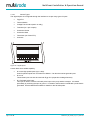
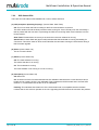
7.3.2.1
Sensor Types
The digital inputs are configured through the interface to accept many types of inputs.
•
Flygt FLS
•
Thermal Switch
•
Voltage Free Contact (switch or relay)
•
Transistor (inc. opto-coupler)
•
Conductive Probe
•
Conductive Seal
•
Thermistor (non-linear PTC)
•
Counters
Figure 30 - Digital Inputs
Certain DIN’s have added capability:
•
DI 19-20 High speed inputs (up to 1kHz).
Used for pulsed inputs such as Pulse Flow Meters. Can also be used as general inputs.
•
DI 16-18
These three inputs can also be used with Flygt CLS (Capacitive Leakage Sensors)
•
DI 1 Fail-safe probe input.
This input is used to connect a fail safe probe input to the pump station manager. It is tested
periodically by switching the input to ground. If a break or disconnection is detected a probe fault is
generated. See the MultiTrode website for details on the fail-safe probe.
Page 34 of 188
MultiSmart_IO_Manual_A4_v2-1_R13.doc
MultiSmart Installation & Operation Manual
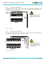
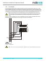
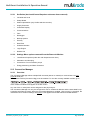
7.3.2.2
10 Sensor Probe (or Ball Floats)
An example of how to wire a 10 sensor probe is shown below. If no failsafe sensor is available on the probe,
you should still wire the 10 sensors from DI 2 – DI 11 (to match the MultiSmart default configuration). DI 1
can be used for any other general Digital Input.
NOTE:
Where a FailSafe probe is being
installed, Probe wire 11 is the
FailSafe connection and is wired
to DI 1.
Figure 31 - Probe Inputs
7.3.2.3
Single Sensor Probe (or Ball Floats)
An example of wiring single sensor probes is shown below. Any input could be used as long as they have
been configured to accept a single sensor probe using the interface.
NOTE:
Where FailSafe probe/s are being
installed, although each probe
may have a FailSafe wire; only
one (1) probe can be connected
to the FailSafe input.
Figure 32 - Single Sensor Inputs
MultiSmart_IO_Manual_A4_v2-1_R13.doc
Page 35 of 188
MultiSmart Installation & Operation Manual
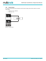
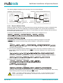
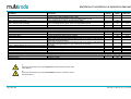
7.3.3
Digital Volt-Free Outputs
The pump control board has seven 240V, 5A, and digital volt-free outputs:
Figure 33 - Digital Volt-free Outputs
•
DO 1-4 – Isolated voltage free contacts.
•
DO 5-7 – Common rail voltage free contacts.
NOTE:
DO1-4 ARE CONFIGURED BY DEFAULT. HOWEVER, WHEN THE SYSTEM HAS LESS
THAN 3-PUMPS THE RELEVANT DIGITAL OUTPUTS WILL NOT BE CONFIGURED, E.G.
WITH 2-PUMPS DO3 IS NOT CONFIGURED.
NOTE:
MULTITRODE RECOMMENDS THAT SNUBBERS ARE FITTED TO THE CONTACTOR
COILS THE DIGITAL OUTPUTS ARE DRIVING.
NOTE:
MUITIPLE SOURCES CAN BE ASSIGNED TO THE DIGITAL OUTPUT WITH AND, OR
AND XOR OPERATIONS CAN BE DONE TO THE SOURCES.
Page 36 of 188
MultiSmart_IO_Manual_A4_v2-1_R13.doc
MultiSmart Installation & Operation Manual
7.3.4
Analog Inputs
The pump control board has two 4-20mA analog inputs.
•
Maximum Load – 120ohms
•
Resolution 0.2%
Figure 34 - Analog Input - External Excitation: 2-Wire
7.3.5
Figure 35 – Analog Input - External Excitation: 3-Wire
Analog Output
The pump control board has one analog output which produces a 4-20mA output signal. This output can be
used to transmit the water level (or reflect the value in any AIN on the MultiSmart unit) or to control a
Variable Frequency Drive, i.e. VFD. (VFD functionality is an optional feature which needs to be ordered if
required. It can be enabled after purchase.)
•
Maximum Load – 800ohms
•
Resolution 0.2%
Figure 36 - Analog Output
MultiSmart_IO_Manual_A4_v2-1_R13.doc
Page 37 of 188
MultiSmart Installation & Operation Manual
7.4
CPU Board
The CPU Board is the core of the MultiSmart pump station manager and provides serial and Ethernet
communications ports, controls the user interface and has a flash card interface.
7.4.1
Connecting the User Interface Display
Connect the display into the RJ45 socket on the MultiSmart unit CPU Board as shown below.
Figure 37 - Connecting the display cable
WARNING: DO NOT CONNECT THE DISPLAY INTO THE ETHERNET PORT
7.4.2
Ethernet Port
The CPU Board has a 10Mbit/s, RJ45, Ethernet port. This port can be used for SCADA communications
when using radios with an Ethernet port.
7.4.3
Serial Ports
There are three RS232 (DB-9 - male) serial ports on the CPU Board. Any of these ports can be assigned to
a communications channel. See Error! Reference source not found. for more information. All I/O lines are
implemented.
The MultiSmart serial ports use the standard RS232 pinouts as tabled below.
Pin
Name
Abbrev
Direction
1
Carrier Detect
CD
Input
2
Receive Data
RX
Input
3
Transmit Data
TX
Output
4
Data Terminal Ready
DTR
Output
5
System Ground
GND
-
6
Data Set Ready
DSR
Input
7
Request to Send
RTS
Output
8
Clear to Send
CTS
Input
9
Ring Indicator
RI
Input
Table 2 - Serial Port Pin Out
Page 38 of 188
MultiSmart_IO_Manual_A4_v2-1_R13.doc
MultiSmart Installation & Operation Manual
7.4.4
Flash Memory Card
The flash memory card socket takes standard CF memory cards. MultiTrode recommends the use of
SanDisk CF cards as these have been tested by MultiTrode. Some brands may not function correctly. The
CF card can be used in a number of ways:
•
As extra storage space for data logging.
•
To install new firmware.
•
Can be used to load or save configuration files into the MultiSmart unit.
WARNING:
Before removing the compact flash card, you must press the yellow save CF data button. Failure
to do so may cause corruption of data or damage to the flash card.
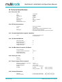
7.5
DSP Board
The Digital Signal Processor board handles the I/O, communicates between multiple I/O modules and is
where the main power supply is connected.
7.5.1
Power Supply Connector
The 12-24VDC power supply is connected into the DSP board as shown below:
Figure 38 - Connecting the power supply
MultiSmart_IO_Manual_A4_v2-1_R13.doc
Page 39 of 188
MultiSmart Installation & Operation Manual
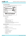
7.5.2
DSP Status LEDs
There are four DSP status LEDs labelled COP, Power, Offline and Fault.
(a) COP (Computer Operating Properly) (Correct State: Slow Flash)
Off: This occurs when the DSP is waiting for the first communications on the bus.
This LED remains off until the Host processor starts running I/O. If the LED stays off, then most likely a
fault is present with the bus and it is preventing the DSP from receiving initial communications from the
Host processor.
Slow Flash: Flashes about once every 2 seconds when the main software is running.
Quick Flash: A faster flash rate (approx 2Hz) indicates that the bootloader is running and waiting for
commands. This will be seen for about 5 seconds after the Host starts running the I/O and also during a
DSP firmware upgrade.
(b) Power (Correct State: On)
This is a Power indicator.
(c) Offline (Correct State: Off)
Off: The main software is running.
This means that the I/O is running.
On: The bootloader is running.
The main software is not running so no I/O is running.
(d) Fault (Red) (Correct State: Off)
Off: Status OK
On: At least one of the I/O boards attached has I/O calibration data which the current firmware cannot
handle and as a result, the I/O is not calibrated. Firstly upgrade the DSP firmware and if the Fault LED
remains on, contact MultiTrode as the I/O is not calibrated.
Flashing: This indicates that at least one of the I/O boards found is incompatible with the firmware.
It means that no I/O at all can operate on the unit. Upgrading the DSP firmware should solve the problem.
Page 40 of 188
MultiSmart_IO_Manual_A4_v2-1_R13.doc
MultiSmart Installation & Operation Manual
7.5.3
Add PSU & Battery Backup
7.5.3.1
Connections to the Power Supply
The figure below illustrates the connections to the Mean Well power supply, model AD-155A, (Part No. PSUBATT-02).
L
(AC)
N
NC B+ B-
(AC)
V1
V1
ADJ
RESET
Mains Supply
Ground
To Battery
To MultiSmart
Potentiometer
Figure 39 - Power Supply Terminal Block Connections
7.5.3.2
Setting the Correct Charge Voltage
To help maximize battery life it is essential that the correct charge voltage from the power supply to the
battery is set. The correct value is 13.7VDC +/- .1VDC*.
* This value applies to the current 12VDC, 28Ah batteries supplied (Yuasa and Panasonic brands - alternative brands
may however be supplied).
To verify the charge voltage:
Measure the voltage between terminals B+ and B-
To alter the charge voltage:
Adjust the small potentiometer (labelled V1 ADJ) until the correct value is
displayed.
7.5.3.3
Power Supply Reset
NOTE:
If mains power is lost and the connections to the battery are removed and then reconnected, it will
be necessary to reset the power supply in order to restore operation (unless mains power is also
restored).
The reset connector is located on the right hand side of the terminal connections on the power
supply (labelled "RESET"). Bridge the two terminals within the reset connector to reset the power
supply.
MultiSmart_IO_Manual_A4_v2-1_R13.doc
Page 41 of 188
MultiSmart Installation & Operation Manual
7.5.4
CAN Bus & Expanded I/O
I/O expansion units are connected to the main MultiSmart unit using a CAN Bus network or through the
Ethernet *RJ45) connector (See Section 14.4). Any I/O module which supports DNP and MODBUS
communication can also be interfaced to the MultiSmart which requires custom Engineering. MultiSmart
units are preconfigured to support four such Ethernet expansion modules mentioned below.
ADAM-6017
ADAM-6050
ACROMAG-961
ACROMAG-983
The CAN bus baud rate and the device ID are set using the dial switches shown below. The ID must be
unique for each device on the CAN bus.
The baud rate should be set to the same speed on every device connected to the bus. Select a suitable
speed for the length of cable between devices as shown in the table below.
Baud Rate
\
Max Cable Length
0
125Kbps (default)
500m
1
10Kbps
1km
2
20Kbps
1km
3
50Kbps
1km
4
100Kbps
500m
5
125Kbps
500m
6
250Kbps
250m
7
500Kbps
100m
8
800Kbps
50m
9
1Mbps
25m
Figure 40 - CAN Bus Settings
If you change the CAN bus baud rate on the unit you will also need to make the same change in the
configuration. Go to:
and select the appropriate value.
Page 42 of 188
MultiSmart_IO_Manual_A4_v2-1_R13.doc
MultiSmart Installation & Operation Manual
7.5.5
CAN Bus Settings
Master
CAN
456
456
23
78
78
23
Slave
901
901
78
01
78
23
CAN
456
9
23
CAN
456
9
Master
CAN
01
Slave
CAN Cable
Figure 41 - Connecting Expanded I/O
Note:
The CAN Bus Termination is set to ON for standalone MultiSmart units. Termination is only set to ON
when this device is the LAST device on the CAN Bus network.
Hardware
Configuration
Master Unit
First Slave
Second Slave
Comment
CAN Bus
Termination
CAN
ID
CAN Bus
Termination
CAN
ID
CAN Bus
Termination
CAN
ID
Master device only
ON
1
n/a
n/a
n/a
n/a
Default setting
Master + Slave
OFF
1
ON
2
n/a
n/a
Single slave device
Master + Slave(s)
OFF
1
OFF
2
ON
3
Figure 42 - CAN Bus Settings - Single unit only
Figure 44 - CAN Bus Settings – Intermediate Slave Unit
MultiSmart_IO_Manual_A4_v2-1_R13.doc
Multiple slave devices
Figure 43 - CAN Bus Settings – Master Unit
Figure 45 - CAN Bus Settings – Last Slave Unit
Page 43 of 188
901
23
456
CAN
456
CAN
78
www.multitrode.com
78
V+ (Red)
CANH (White)
Shield
CANL (Blue)
V- (Black)
456
CAN
23
456
23
Slave Unit
23
CAN
901
Master Unit
901
Page 44 of 188
901
MultiSmart Pump Station Manager
CAN BUS Cable Connection
MultiSmart Installation & Operation Manual
78
78
Figure 46 - CAN BUS Cable Connection Wiring
MultiSmart_IO_Manual_A4_v2-1_R13.doc
MultiSmart Installation & Operation Manual
7.5.6
CAN Status LEDs
Consists of 4 LEDs labelled; Offline, Error, TX and RX.
(a) Offline (Correct State: Off)
Off: The CAN bus sub-system is in Operation mode.
This means that everything is up and running and the Slave (DSP) is completely configured and
sending status data to the Master (Host processor).
On: The CAN bus sub-system is not in Operational mode.
Slave (DSP) to Master (Host processor) communications have not been established.
This LED normally activates soon after power-up (whilst it is waiting for and receiving configuration from
the Master (Host processor). Once the Master has configured the Slave (DSP), then the Master will
send a command to switch the CAN sub-system to Operational mode. The Slave will then start sending
status data automatically to the Master.
(b) Error (Correct State: Off)
This LED indicates errors on the CAN bus.
This can be due to either a connection or termination problem on the bus or to a Baud Rate mismatch
between either the Master or one of the slaves. Bad connections, bit errors (due to poor wiring or too
long a bus) can also cause bus errors.
The Slave and the Master both attempt to recover automatically from the errors but unless the fault is
rectified the errors will continue.
Off: Status OK
On: The Slave has switched to "Error Passive" mode on the bus.
This means that the unit will receive but not transmit. This is due to the detection of packet errors on the
bus. The unit will attempt to recover automatically.
Flashing (approx 5Hz): The Slave has switched to "Bus Off" mode.
This means that the unit has stopped communicating on the bus. The unit will attempt to recover
automatically. The auto-recovery mechanism will mean that the total duration of the flashing period will
be short.
(c) TX & RX (Transmit and Receive) (Correct State: fast flash)
Indicates activity on the bus. These LEDs simply flash with the data on the bus.
At high baud rates the LEDs are only illuminated briefly so they will appear fairly dim - this is normal.
MultiSmart_IO_Manual_A4_v2-1_R13.doc
Page 45 of 188
MultiSmart Installation & Operation Manual
7.6
Energy Monitoring & Motor Protection Board
The Energy Monitoring and Motor Protection Board is an optional board for up to 3 pumps. It monitors single
or 3-phase motor currents for up to 3 pumps, direct from CT’s, and provides motor protection and power
monitoring. The board also carries out an automatic 1000v insulation resistance test of the motor windings.
An additional 5 digital outputs and 3 analog outputs are on board.
Note: Power monitoring requires 3-phase supply monitoring located in the same MultiSmart enclosure.
The 3PC board has 3-phase supply inputs. Therefore you must have a 3PC board and a 3MP board in
the same enclosure to do power measurements. MultiSmart can monitor single phase supply as well.
7.6.1
Insulation Resistance Tester
The 1000VDC Insulation Resistance Tester is connected to the pump motor windings and periodically tests
them for insulation breakdown. See Section 17.2 for details on how to configure the tester.
Figure 47 – Connecting the IRT
Insulation resistance measurements are performed when the motor is stopped. Therefore the motor windings
must be connected in a star or delta configuration when it is stopped in order to ensure all windings are
tested. The MultiSmart can be set with multiple thresholds for the Insulation Resistance Test. The default
setting of this warning is not to fault the pumps and to provide only an indication.
Wire one winding from each motor controlled by the MultiSmart pump station manager.
Connect the Protective Conductor Terminal to the Earth Conductor connected to the motors.
Note: Follow the manufacturer’s guidelines regarding motor insulation testing when using soft starters or
VFD’s. Functionality is included in the software so the DOUT’s can drive isolation contactors while IRT is
in progress.
7.6.2
Digital Volt-Free Outputs
The board has five isolated voltage free contacts rated for 5A at 240V AC.
Figure 48 - Digital Volt-free Outputs
Page 46 of 188
MultiSmart_IO_Manual_A4_v2-1_R13.doc
MultiSmart Installation & Operation Manual
7.6.3
Current Inputs
The Energy Monitoring and Motor Protection Board has three sets of three-phase current inputs. These
measure between 0-5A and are connected to the secondaries of external CT’s to measure higher currents.
The CT’s must be wired with the correct polarity and ensure that the current phase is corresponding to the
voltage phase. Shielded twisted pair cables are recommended and only the shielding should be grounded.
This ground can be connected either at the MultiSmart end or both at the MultiSmart and at the CT’s.
Note: During the wiring of CT’s if the polarity is wrong the current reading will be correct. However the
power and energy calculations will be wrong. MultiSmart is capable of detecting the difference in polarity.
The phase rotation fault in the MultiSmart can be enabled during installation to verify if the polarity is
correct.
During CT section two things that are to be considered are the input resistance of around 40mΩ for the
MultiSmart terminal & the resistance of the copper wire used for the installation.
Figure 49 - Current Inputs
Note: The CT’s must not be grounded/ earthed. Otherwise incorrect current readings will be measured.
MultiSmart_IO_Manual_A4_v2-1_R13.doc
Page 47 of 188
MultiSmart Installation & Operation Manual
7.6.4
Analog Output
The energy monitoring and motor protection board has three analog outputs which produces a 4-20mA
output signal.
•
Maximum Load – 800ohms
•
Resolution 0.2%
Figure 50 - Analog Output
Page 48 of 188
MultiSmart_IO_Manual_A4_v2-1_R13.doc
MultiSmart Installation & Operation Manual
8
PumpView Hardware Setup
PumpView is a web-based monitoring and control system. There is no software to install, and no server or
radios required. All that is needed is a web browser and a cellular based internet connection at the site(s).
While primarily aimed at the water and wastewater sector, it can be used in a variety of industries.
Once the hardware is installed and the MultiSmart configured, the site can be monitored and controlled via
the web. Fault conditions can be configured to generate alarm messages and sent by email or to a cellular
phone.
CAUTION:
To avoid damaging the modem, always have an antenna connected before applying power to the
modem. Failure to do so may result in damage to the modem.
NOTE:
The antenna must be installed outside the panel. A standard omni-directional antenna as
supplied by MultiTrode (smooth cylinder or rod with no protusions) should be mounted
vertically, such that the cable exit point is directed towards the ground. This will ensure
correct operation and prevention of water ingress into the antenna. Antennas are unlikely
to funtion if they are directed horizontally. Ensure the cable is not kinked or bent tighter
than a 25mm (1") radius curve.
Using the RS232 cable provided, connect the modem to the MultiSmart unit on serial 3 (as shown in Figure
51.)
Do not connect power to the modem unless an
antenna is connected.
Powering the modem without an antenna may
cause damage to the modem.
Antenna
PumpView Modem (GPRS or CDMA)
Figure 51 – Connecting the PumpView modem to MultiSmart
MultiSmart_IO_Manual_A4_v2-1_R13.doc
Page 49 of 188
MultiSmart Installation & Operation Manual
8.1.1
Cellular Modem (PumpView) Setup
The following setup is typically completed prior to shipment but circumstances may arise when this
procedure must be performed on-site.
Si te ID:
900
Modem is not configured.
The previous modem
configured is highlighted.
ATT Sony Ericsson GM28
ATT MultiTech
Telstra Sony Ericsson Gm29
Telstra Sony Landcell 819s
Vodafone Sony Ericsson Gm29
Telstra Wavecom
Vodafone Wavecom
Telstra SAM 3G
Description:
Verizon USA as th e carr ier usi ng a
Lan dcell 819s CDMA Mode m.
Figure 52 –Modem Setup Screen
• Enter the 4 digit Site ID (this is supplied by MultiTrode)
• Select the modem (based on the Telco and the modem brand)
• Depending on the Telco, a Username may be needed. The text “Username:” will appear on the left
hand side if a username is required.
• The username has the format:
pv[Site ID]@multitrode.com
where [Site ID] is the same as the 4 digit number previously entered above, e.g. pv1009@
multitrode.com
Press the Edit button to change or to enter a Username, make the changes then press Save
• The Password should not be changed from the default (displayed as xxxxxxxxx)
• Press Save and then Restart Now
The MultiSmart will reboot and cellular communications should be established within a few minutes.
8.1.2
Fault Finding
For the Sony Ericsson, Wavecom and SAM 3G modems, an LED on the modem will flash when power is
applied and the device is communicating (it may take a minute or so to establish communications).
If the LED is on but not flashing this means it cannot connect to the cellular network. If you have previously
determined that there is adequate signal strength for this site, it may indicate a temporary cell tower problem.
However, it is more likely to indicate that there is a signal strength problem at this location. Possible
solutions are:
•
Using a higher gain antenna
•
Installing the antenna at a higher point
Page 50 of 188
MultiSmart_IO_Manual_A4_v2-1_R13.doc
MultiSmart Installation & Operation Manual
9
Quick Commissioning Guide
The MultiSmart is pre-programmed with a number of standard configurations for typical water/wastewater
applications. This includes:
•
Pump station manager with local level
•
Pump station manager with remote level (reservoir)
•
Reservoir monitor communicating with remote pump station
The Setup Wizard in the Settings menu takes you through a number of questions to configure the product.
Note: If the unit has already been setup by a previous user then Security may be enabled either via a
DIN or by a PIN number. Refer to Section 11 for more detail.
Station Settings - Page 1 of 3:
Set Points
I/O, Faults, & Level
Level and alarm setpoints, enable/disable
alarms, delays, maintenance mode & level
simulation
Link faults to inputs, configure faults,
primary and backup level source, configure
AOUTs & DOUTs
Setup Wizard
Station Optimization
Commission a station - Fill/Empty Mode,
number of pumps, wells, level device
Alternation & Grouping
Odor reduction, well-clean-out, blocked
pump detection, max run time, max station
starts, max pumps to run, profiles etc.
Commission / Decom
Alternation, fixed sequence and multiple
groups of pumps
Main
Take pumps in and out of service
Advanced
More ...
Figure 53 - Settings Screen
When a pump station manager is selected this also establishes one of the standard I/O connection diagrams
(see Section 7.2 to Section 7.2.4). The MultiSmart pump station manager establishes 1 of 4 standard
connection diagrams depending on whether the configuration is:
•
2 pumps with a MultiTrode Probe / Duo probe
•
3 pumps with a MultiTrode Probe / Duo probe
•
2 pumps with a 4-20mA level device
•
3 pumps with a 4-20mA level device
These connections diagrams have a complete set of pump faults wired in (contactor auxiliary input, C/B off
trip, pump seal and thermal (or Flygt FLS), thermal overload).
Note: Disabling any faults not required is a very simple task – see Section 9.3 at the end of the Quick
Commissioning Guide.
MultiSmart_IO_Manual_A4_v2-1_R13.doc
Page 51 of 188
MultiSmart Installation & Operation Manual
9.1
Setup Wizard Flow Diagrams
The following diagrams outline the steps taken to complete the Setup Wizard.
9.1.1
Wizard Start
Setup Wizard
Important Note for User
Displayed on Screen
Cancel
Return to Settings Screen
Next
Enter a New Site Key ?
Yes
Enter New Site Key
Back
Cancel
No
Choose either Pump Station
or Reservoir
Pump station
Refer to Pump Station
Flow Diagram
Reservoir
RTU
(No pump controller
or display)
Refer to Reservoir
Flow Diagram
Refer to Reservoir
Flow Diagram
Figure 54 - Setup Wizard - 1 of 4
Page 52 of 188
MultiSmart_IO_Manual_A4_v2-1_R13.doc
MultiSmart Installation & Operation Manual
9.1.2
Pump Station Setup
Select Pump Station Mode:
Empty / Fill ?
Choose Measurement Units:
Imperial / Metric
Select the Number of MultiSmart
Units in the Pump Station
Select the Type of Board
Installed in Unit 1:
3PC / 3MP / None
Enter the Number of Wells in
the Pump Station
>
1 Well
...
Select whether the Wells
will Operate Independently
Yes / No
1 Well
Enter the Number of Pumps
in the Well
Choose the Type of Level Device
used by the Well:
Probe / Duo Probe / Analog
/ Remote Level
Enter the Number of
Pumps in each Well
Remote
Level
Probe / Duo Probe / Analog
Wizard checks
how many Pumps have been
Configured
Choose DNP3
Configuration:
A/B/C
1-3 Pumps
> 3 Pumps
Seal, thermal, FLS
connections
Set Supply Voltage:
Single phase or three phase
:
480V / 415V / 240V / 208V
or Enter Custom Value
DNP3 Address Setup
Check Setup Summary
Yes / No
Yes
New Settings Applied and
Unit Restarted
No
Return to Select Station
Type Screen in Setup
Wizard Drawing
Figure 55 - Setup Wizard - 2 of 4
MultiSmart_IO_Manual_A4_v2-1_R13.doc
Page 53 of 188
MultiSmart Installation & Operation Manual
9.1.3
Reservoir Setup
Figure 56 - Setup Wizard - 3 of 4
Page 54 of 188
MultiSmart_IO_Manual_A4_v2-1_R13.doc
MultiSmart Installation & Operation Manual
9.1.4
RTU Setup
Select the no. of MultiSmart
units in the Pump Station
Select the type of Board
installed in Unit 1:
3PC/3MP/None
DNP3 address setup
Check setup summary
Yes / No
Yes
No
New settings applied
and unit restarted
Return to “select station type” screen
in Setup Wizard diagram
Figure 57 - Setup Wizard - 3 of 4
MultiSmart_IO_Manual_A4_v2-1_R13.doc
Page 55 of 188
MultiSmart Installation & Operation Manual
9.2
9.2.1
Setup Wizard Notes
Activating New Modules
Each MultiSmart unit comes with certain modules enabled. New modules are activated with a new site key.
New site keys can be entered at any time when new modules need to be activated.
9.2.2
Fill (Charge) or Empty (Discharge) Modes
A pump station can be configured to either Fill (Charge), or Empty (Discharge) the well.
9.2.3
Number of MultiSmart Units in Installation
Multiple MultiSmart units can be connected together using the CAN Bus interface. This allows additional I/O
to be added to the station if required. A “unit” is defined as a separate DIN mounted housing containing at
least a DSP Board and one other board, a 3PC Pump Control Board for example.
9.2.4
Configuring the Type of Board Located in the Bottom Slot
There are four board slots in a MultiSmart unit. By setting what type of board is located in the bottom slot the
setup wizard can determine the correct I/O configuration for the unit.
9.2.5
Number of Wells in Station
A station can have up to three wells.
9.2.6
Level Devices
There is a choice of Probe (MultiTrode conductive probe), Duo Probe (MultiTrode conductive probe with
pressure transducer, Analog (e.g. Pressure transducer or ultrasonic) or Remote Level. Remote level is
typically used where the pump station is pumping to a reservoir.
Note: If you later want to change the level device, there is no need to go back through the setup
wizard, simply see Section 14.8.
9.2.7
Number of Pumps in each Well
If more than one well is configured, you will be asked to repeat the process of selecting the number of pumps
for each well(s).
Note: The number of pumps available for the system is limited to 3, 6 or 9 depending on the options you
have purchased.
Note: If more than 3 pumps or more than 1 well are selected then no I/O defaults will be
applied.
Page 56 of 188
MultiSmart_IO_Manual_A4_v2-1_R13.doc
MultiSmart Installation & Operation Manual
9.2.8
Select Fault Input Sensor Type
The digital inputs can be setup to handle either a Flygt FLS sensor, or a Thermal/Seal type sensor direct
from the pumps.
Note: This specific pump fault input is identified because the FLS uses one input, whereas a typical
thermistor/seal combination uses two inputs. The answer to this question establishes a complete
connection diagram
If you have neither a Flygt FLS sensor or a Thermal/Seal type sensor, choose None. You may also want to
disable any other faults from the connection diagram that are not actually connected in your panel. Refer to
Section 9.3 at the end of Quick Commissioning in Section 9 Quick Commissioning Guide.
9.2.9
Configure Phase to Phase Voltage
A phase to phase pump supply voltage is required in order for the voltage protection functionality to work
correctly. Either select one of the options, or enter a custom voltage.
9.2.10
Choose DNP3 Configuration (Reservoir Setup Only)
One of three standard DNP3 configurations must be chosen when setting up the MultiSmart as a Reservoir
monitor. These set the method of communication between the reservoir and the remote pump station.
Configuration B is the preferred method. It will setup the DNP3 configuration for situations where a direct
communications link between the pump station and reservoir station exists.
Configurations A and C are used where a direct communications link is not present. Instead, these
configurations setup the MultiSmart to receive the level via a DNP Master (MTU).
See section 21 for more information.
9.2.11
Accepting New Configuration & Resetting Controller
The final commissioning screen will display a summary of all settings entered. Check the configuration
carefully and press the Yes button if it is correct.
All current settings will be replaced by the new configuration. The controller will restart with the new settings.
This process will take a few minutes to complete.
MultiSmart_IO_Manual_A4_v2-1_R13.doc
Page 57 of 188
MultiSmart Installation & Operation Manual
9.3
Unassign Any Faults Not Used
To speed up the process of establishing a new station, four standard configurations are used. These include
a number of useful pump faults inputs, some of which may not be needed or not available in your station.
Note: Some of the standard configurations include a contactor auxiliary input for each pump. If no
contactor auxiliary is connected to this input a pump fault will be generated.
To unassign any fault inputs, go to Settings/I/O faults and level/Digital Inputs
Settings
I/O Faults, & Levels
Digital Inputs
This screen will show you how all DIN’s have been assigned:
Digital Inputs
Assigned
Digital Input
Input
Top Board DIN 01
Pump 1 Motor Overtemp
Top Board DIN 02
Pump 1 Seal
Top Board DIN 03
Pump 1 Thermal Overload
Top Board DIN 04
P1 Contactor Auxiliary
Top Board DIN 05
P1 C/Breaker Off/Trip
Top Board DIN 06
DIN.6
Top Board DIN 07
Pump 2 Motor Overtemp
Top Board DIN 08
Pump 2 Seal
Top Board DIN 09
Pump 2 Thermal Overload
Top Board DIN 10
P1 Contactor Auxiliary
This screen is for display only. To edit, select Faults or General.
Back
PgDn
PgUp
Faults
General
Figure 58 – Digital Input assignments
Select the Faults option:
This screen identifies all faults that have been pre-configured in the
system, along with any that are currently linked to DIN’s.
Pump 1 CLS
Pump 1 FLS
TopBoard DIN 12
Pump 1 Seal Fault
Pump 1 Thermal Overload
TopBoard DIN 14
Pump 1 Motor Overtemp
Pump 1 CB Off/Trip
TopBoard DIN 13
Pump 1 Contactor Auxiliary
TopBoard DIN 15
Pump 1 Critical Fault
Pump 1 Delay Fail
Pump 1 Non-Critical Fault
Figure 59 - Pre-configured Faults
Page 58 of 188
MultiSmart_IO_Manual_A4_v2-1_R13.doc
MultiSmart Installation & Operation Manual
Select the fault you want to unassign, and press the Unassign softkey. Repeat for any other faults to be
unassigned, and press the Save softkey.
For certain faults which are assigned or unassigned the MultiSmart will need to be restarted. If restart is
necessary the following prompt will come up on the screen, from which choose the desired option, keeping in
mind that a restart is required for those changes to come into effect.
Warning:
The changes you have made will not take effect
until the unit is restarted.
If you need to make other changes, then you should
choose the Continue option, and ensure that you
restart the unit when all of your configuration
changes are complete.
Restart Now
Restart Later
If this is your only change or last change, then you
should choose the Restart Now option.
Continue
Figure 60 – Select to Restart Now or Continue
Choose Restart Now if you have completed configuring faults. Choose Continue if you still have other
configuration changes to make or Restart Later to continue the operation or make further changes without
again being warned for a restart. However the last option will be shown as a fault which can only be cleared
with a MultiSmart restart.
Figure 61 - Restart Screen
MultiSmart_IO_Manual_A4_v2-1_R13.doc
Page 59 of 188
MultiSmart Installation & Operation Manual
9.4
Level Simulation Mode
9.4.1
Simulating Levels for Safety/Commissioning Purposes
The pump station manager can simulate levels for safety or commissioning purposes. This function allows
you to increase or decrease the level in 1% steps from the keypad. Using this facility you can test the control
panel before it is installed at the pump station.
Navigate to the Level Simulation screen:
Figure 62 – Simulating Levels
•
Press the Toggle button
•
The time remaining will start counting down to zero. When the time runs out the level simulation
mode will automatically turn off
•
Navigate back to the Main screen
•
Use the up and down arrows on the keypad to raise or lower the simulated level
•
When you have completed your test of the station, you can either let the level simulation time out,
or you can go back to the level simulation page and Toggle Off.
Health and Safety Feature: This feature allows operators to test pump and alarm levels without
having to open the pit cover to move level sensing devices.
WARNING: The pumps will respond to the simulated level exactly as they would to a real level.
Therefore, it is possible to run the pumps with no actual liquid IN THE WELL, thereby running the
pumps dry and damaging them.
Page 60 of 188
MultiSmart_IO_Manual_A4_v2-1_R13.doc
MultiSmart_IO_Manual_A4_v2-1_R13.doc
External
I/O Modules
LCD
Keypad
Level, pressure, organic
biological sensor inputs
Supply voltage monitoring
Variable Frequency Drive
Thermal, seal, contactor
auxilliary, circuit breaker,
input/output, pump relay
control, motor protection.
IEC 61131- 3
(ISaGRAF)
Logic Engine
Flow Monitoring
Date/Time
Security
Advanced Settings
CPU
Thermal, seal, contactor
auxilliary, circuit breaker,
input/output, pump relay
control, motor protection.
Pump 3
Config
backup/restore
Data back up
Data Logging
Events, Faults etc.
Motor Protection
Insulation resistance
Test
Commissioning/
Decommissioning
Pumps
Order reduction
Max run time
Max pump to run
Well cleanout
Minimize excessive
starts
Well washer
Block pump
detection
Max starts per hour
Advanced Config
Edit
Supply Protection
Software
Modules
Optimization
Profiles,
Each
Profile can be
Configured
and
Saved
for later use
Profile
Station Optimization
High frequency & Low Frequency I/O available
Pump 2
MULTISMART PUMP STATION MANAGER
RTU Module
Multiple master and slave
DNP3 master/slave
Modbus master/slave
Serial and ethernet
System information
Hours run statistics
Pump Information
Display
Customization
Analog and Digital Input/Output
Thermal, seal, contactor
auxilliary, circuit breaker,
input/output, pump relay
control, motor protection.
Pump 1
Fault Monitoring
Set Points
Level/Control
Alarm
Delay settings
Enable/Diable Alarms
Standard
Special
Fixed Strict
Hours Run
Pump Starts
Efficiency
N =>1
One MultiSmart can handle
up to 6 pumps which can be
extended to 9 pumps with
certain limitations
MultiSmart Installation & Operation Manual
Part 3 – Advanced Settings
10 High Level Overview
10.1 MultiSmart Pump Station Manager Overview
MultiSmart Pump Station Manager has enormous functionalities built in, some of which are shown in the
figure below. Functionality wise MultiSmart can be considered as a Pump Controlller and an RTU integrated
together. MultiSmart pump station manager can handle all the common water and sewage pump station
applications. But its capabilities are not limited to that. MultiSmart Pump Station Manager has support from
PLC functionality which can be configured to meet all the advanced requirements.
Figure 63 – MultiSmart Pump Controller Overview
Page 61 of 188
MultiSmart Installation & Operation Manual
10.2 Pump Controller
The pump controller module provides all of the logic to control and monitor water and sewer pump stations.
In conjunction with the LCD module (and the LCD itself), it provides a complete operator interface for control,
monitoring and commissioning.
Pump Controller
Fill/Empty & Pump
Setpoints, Alarm
Setpoints, Delays
Profiles
RTU
Level
Sensing
Station
Optimization
Medium
RS232
TCP/IP
UDP/IP
Cellular
Pumps
& Groups
Add ito nal Master & Slaves
DNP3 Ma ster/S la ve
Power & Energy
Monitoring/
Motor Protection
Supply Protection/
Monitoring
Add ito nal Master & Slaves
Modbus Ma ster/S lav e
Data Logger
Flow
Fault Module
Security
Logic Engine
PLC - IEC61131-3
(ISaGRAF)
Figure 64 - Pump Control Functionality Overview
Page 62 of 188
MultiSmart_IO_Manual_A4_v2-1_R13.doc
MultiSmart Installation & Operation Manual
10.3 Reservoir Monitor
The MultiSmart can also be configured as a Reservoir Monitor. In this mode, there are no pumps to control
so all functionality related to pumps and groups are unavailable. All remaining functionality is the same as
for the Pump Controller Module.
Reservoir Monitor
Alarm Setpoints
Level Sensing
Profiles
RTU
Comms Ports
Comms Protocols
Supply Protection
Data Logger
Flow
Security
Logic Engine
Figure 65 - MultiSmart Reservoir Monitor Overview
MultiSmart_IO_Manual_A4_v2-1_R13.doc
Page 63 of 188
MultiSmart Installation & Operation Manual
10.4 Pump Control Module
10.4.1
Pump Modes
Three pump modes exist for each pump controlled by the MultiSmart Pump Station Manager. They are
Manual, Off and Auto.
If the manual mode is selected the pump will be turned on unless faulty or unavailable and goes to Off mode
when the lower level cut off point is reached. In Off mode the pump will not start, unless put into Manual or
Automatic modes, even when the cut in setpoint is reached. In Automatic mode the advanced pump control
module take over the duties of starting and stopping the pumps.
The Off mode can be disabled from being used, if desired, from the advanced settings menu. As a safety
measure, when this feature is turned off while the pump is already in Off mode, it will remain in that state until
the mode is changed.
10.4.2
Fill / Empty & Pump Setpoints, Alarm Setpoints, Delays
Emptying or filling a well is supported. Each mode has a default set of activation/deactivation points for
pumps and alarms. Four level alarms are supported for each well (where more than one well exists), with
the ability to disable/enable any alarms. Each level alarm has an activation and deactivation point. Activation
and deactivation delays are supported for each pump, as well as inter-pump delays. See Section 12 for
more information.
10.4.3
Pumps & Groups
The module supports up to 6 pumps (depending on the product configuration ordered), which can be
assigned to more than one well if required. Multiple groups of pumps are supported. Typical applications are
jockey pumps and flood pumps. Within a group, pumps can alternate or be in fixed sequence, and maximum
pumps running can be set. Groups of pumps can be alternated or in fixed sequence, and maximum number
of groups running can be set.
Some configuration parameters for pumps relate to whether they are the lead (duty) pump or the lag
(standby) pump. This capability is supported in the module – parameters can relate to the pump position in
the alternation sequence rather than the physical pump, e.g. activation and deactivation delays. See Section
13 for more information.
10.4.4
I/O, Faults & Level Devices
Inputs and Outputs (I/O), Faults and Level Devices are closely related. They all work together to provide the
functionality required to run a pump station.
•
I/O
General purpose I/O can be used to interface to a wide range of devices. Some inputs have extra
capabilities for interfacing to devices such as Flygt CLS sensors.
•
Faults
Faults can be assigned to both digital and analog I/O. Inputs are used to detect faults within the
pump station, such as pump faults. Outputs are used to signal when a pump is present, or to turn
off a pump.
•
Level Sensors
The module supports multiple level sensors, including 4-20mA analog sensors (e.g. pressure
transducer, ultrasonic); MultiTrode conductive probe, ball floats. Support for redundant level
sensing is built-in.
See Section 14 for more information.
10.4.5
Profiles
The module supports multiple profiles. Each profile consists of pump activation/deactivation setpoints, as
well as some station optimization functions (max pumps running, max off time, max run time). Profiles can
be switched via the user interface, via SCADA, or at pre-set date/times. See Section 15 for more
information.
Page 64 of 188
MultiSmart_IO_Manual_A4_v2-1_R13.doc
MultiSmart Installation & Operation Manual
10.4.6
Station Optimization Functions
Many desirable functions are pre-defined, with the user simply enabling/disabling or choosing parameters for
the functions. Functions include:
•
Odour reduction (via maximum off time)
•
Blocked pump detection
•
Maximum run time to switch from inefficient pumps
•
Minimize excessive starts
•
Reduce fat build-up (via random duty start)
•
Maximum pumps running (electrical or hydraulic overload protection)
•
Periodic well clean out
•
Well washer functionality
See Section 16 for more information.
10.5 Energy Monitoring and Motor Protection
An optional Energy Monitoring Motor Protection module can be supplied with the MultiSmart pump station
manager. The module monitors currents, and provides protection from:
•
I2T protection
•
Over and Under current
•
Phase fail (current)
•
Phase rotation (current)
•
Ground (earth) fault
The module also monitors Insulation Resistance values with pump lockout or fault notification when IRT
values fall below a user-defined threshold.
10.6 Supply Protection
The Pump Control/General I/O Board monitors the three phase supply through the “Mains Voltage
Monitoring” inputs. Single or 3 phase supplies can be monitored by the MultiSmart. The voltage is constantly
measured and is used to detect the following conditions:
•
Under Voltage
•
Over Voltage
•
Phase Imbalance (or Phase Failure)
•
Phase Rotation
10.7 Data Logger
The MultiSmart unit has a datalogger. The logged data can be viewed directly on the screen, or downloaded
onto a laptop and viewed via Excel, Access, or any other reporting/databasing tool. The datalogger stores
approximately 50,000 events and faults. Each event or fault is date/time stamped. See Section 19 for more
information.
10.8 Flow
The flow module is used to calculate inflow, pump flow rates and total station volume. This allows flow to be
derived without needing a flow meter. See Section 20 for more information.
MultiSmart_IO_Manual_A4_v2-1_R13.doc
Page 65 of 188
MultiSmart Installation & Operation Manual
10.9 Fault Module
The fault module handles pump and station faults. Many pre-defined faults exist, e.g., thermal overload,
contactor auxiliary and Flygt FLS. A fault only needs to be assigned to an I/O (within the configuration) to
begin to function. New faults can of course be defined.
Any fault can be configured to lock out a pump, well or station until a manual (or SCADA) reset is performed.
A fault can also be configured to allow the pump to become available when the fault clears, or after a
deactivation delay.
10.10
Security
The MultiSmart can restrict access to the configuration menus. Each user is assigned a PIN number which
they will have to enter before they are allowed access. By enabling the security users will not be able to clear
the history of the logged data from the information screen. Alternatively, a digital input can be used instead of
a PIN. User access rights are managed by an administrator. See Section 11 for more information.
10.11
PLC Extension (IEC61131-3)
ISaGRAF, a control software environment which supports all of the internationally recognized IEC61131
control languages and offering a combination of highly portable and robust control engine, is available in
MultiSmart. MultiSmart currently only supports ISaGRAF version 5. Earlier versions of ISaGRAF are not
supported. See Section 24 for more details.
10.12
Logic Engine
A simple, Boolean, logic engine has been built into the MultiSmart to allow basic customization of control
capabilities where the existing functionality is not suitable. It uses mathematical expressions which are
evaluated at regular intervals to determine if they are true or false. The expressions are associated with a
tag within the MultiSmart to create actions when an expression changes state. See Section 25 for more
information.
10.13
RTU
The MultiSmart can be supplied with an optional RTU. Supported communication protocols are Modbus and
DNP3 with security. The MultiSmart can also be shipped just as an RTU without any pump controller
functionality or user interface. See Section 21 for more information.
The diagram below illustrates the extensive communication capabilities of MultiSmart, even though in
practice it is highly likely to use all of these in the same installation. MultiSmart can be interfaced with most
of the common industry standard equipments and SCADA networks.
Page 66 of 188
MultiSmart_IO_Manual_A4_v2-1_R13.doc
MultiSmart_IO_Manual_A4_v2-1_R13.doc
ADAM /
ACROMAG
MODBUS I / O
MODBUS VFD
MODBUS
MODBUS
DNP3
Ethernet Radio
DNP3
Cellular Router
DNP3 Ethernet
DNP3
HMI
Ethernet Switch
CAN 1
Ethernet
CAN 2
S2
CAN 2
MultiSmart
CAN 1
S1
MultiSmart
MODBUS + DNP3
S3
Pumpview Serial
Modem
DNP3
Radio (DNP3)
MODBUS I/O
Web Clients
NOTE:
Memory contraint depends
on no. of tag points/no. of pumps.
MODBUS
Pumpview
Server
MultiSmart Installation & Operation Manual
Figure 66 - MultiSmart Communication Capability Overview
Page 67 of 188
MultiSmart Installation & Operation Manual
11 Security
The MultiSmart restricts access to the configuration menus by creating users. Users gain access to the
settings menus by either:
•
Entering a 4 digit PIN number when prompted
•
Activating a digital input (a key switch, for example)
Each user is assigned a PIN number or digital input access, by an administrator.
The administrator user account is enabled and a password automatically generated by default at the factory
before despatch. The administrator password can be changed from the Security Screen accessed from the
Settings menus.
Security access for users is not activated until the first user has been configured. The administrator will need
to go to the Security Screen in the settings menus and configure a user to activate access control.
Note: The factory set security password can be found on the inside back cover of the product manual.
Note: It is important the administrator password is kept in a secure location. If the password is lost the
unit may need to be returned to MultiTrode for re-configuration.
Note: The Admin user needs to create an Admin PIN number to enter the Settings menu. This makes
access into the Settings menu relatively easy via a 4 digit PIN, whereas access into administrator user
is intended to be a difficult alphanumeric password.
Note: If the security is enabled, users will not be able to clear the accumulators from the information
screen. Thus the historical data can be secured from being erased.
The administrator is the only user allowed to add, delete or edit user accounts.
To access the security screen go to:
•
enter a PIN if requested and push Continue
•
Go to page 3 of the settings screens and press Security
•
Enter the administrator password and press Continue
Figure 67 – Security Screen
Page 68 of 188
MultiSmart_IO_Manual_A4_v2-1_R13.doc
MultiSmart Installation & Operation Manual
To edit, add or delete a user press Add/Remove Users
The following user settings can be edited:
•
User ID
•
PIN
•
User Name
User ID
Edit User Details
User Name
PIN
1
2
3
DonaldF
PaulO
StuartD
1234
5678
9012
User
Edit
Back
Add New
Delete
Cancel
Save
Figure 68 – Edit User Security Details
To change the administrator password:
•
Press Administrator Settings
•
Enter a new password
•
Press Save
Figure 69 – Change Administrator Password
MultiSmart_IO_Manual_A4_v2-1_R13.doc
Page 69 of 188
MultiSmart Installation & Operation Manual
To configure security to be activated by a digital input press Security via Digital Input
•
Enable security via DIN by pressing the Toggle button
•
Select a digital input tag. By default, this is set to DIN 20 on the top board. Any digital tag in the
system can be selected, allowing greater flexibility then just using Digital Inputs. To choose
another Digital Input, simply use the tag browser to find the appropriate DIN, and choose
ValueDigital (see Figure 71 and Figure 72 in Section 11.1 below).
•
Press Save
Figure 70 – Configure Security via DIN
11.1 Selecting any Digital Tag
The screens below show how to navigate to any digital input. Find IO Module and using the
expand out the tree view to get to the Digital Input you are looking for.
Please Select: Digital Tag
Name
_IO
Type
+/-
button
Select
Node
....CAN Baud Rate
Node
....Demo Case
Attribute In
....Unit
Attribute B
..._1
Node
...Bottom Board
Node
...D cVolts
Node
...Probe
Node
...System
Node
...Top Board
Node
...+ Ain
Node
Clear
Cancel
+/OK
Figure 71 – Tag browser screen
Page 70 of 188
MultiSmart_IO_Manual_A4_v2-1_R13.doc
MultiSmart Installation & Operation Manual
Please Select: Digital Tag
Name
Type
Select
Node
...Top Board
Node
....+ Ain
Node
...._ Aout
Node
_ Din
Node
_1
Node
...CalibACA
Integer Tag
..CalibACC
Integer Tag
...CalibACM
Integer Tag
...CalibDCA
Integer Tag
...CalibDCC
Integer Tag
Save
Cancel
+/OK
Figure 72 – Tag browser screen –continued.
Once you have found the Digital Input (DIN) you are looking for, expand the selection using the
and scroll down to ValueDigital and press OK.
+/-
button,
Note: The tag browser gives you access to any tag in the MultiSmart unit, including tags
generated by the logic engine.
MultiSmart_IO_Manual_A4_v2-1_R13.doc
Page 71 of 188
MultiSmart Installation & Operation Manual
12 Fill / Empty & Pump Setpoints, Alarm Setpoints, Delays
12.1 Fill / Empty (Charge / Discharge)
This parameter is selected during the Setup Wizard, as described in Section 9.
12.2 Default Pump and Alarm Setpoints
The MultiSmart pump station manager has an activation and deactivation setpoint for each pump, and 4
independent level alarm setpoints; high, high-high, low, low-low, each with their own activation and
deactivation points. In the case of multi-well mode, the alarm setpoints are replicated for each well.
The MultiSmart unit applies default setpoints depending on whether fill or empty (charge or discharge) is
chosen during the Setup Wizard.
There can also be multiple profiles – each with their own setpoints (refer to Section 15). For most
applications the default level settings should be appropriate for correct operation of the installation.
High Level Alarm
92%
87%
Figure 73: Empty (Discharge) Mode—Default Normal Levels
High Level Alarm
Off 90%
On 92%
Off 87%
Off 80%
On 40%
Low Level Alarm
Off 15%
On 10%
Figure 74: Fill (Charge) Mode – Default Normal Levels
Page 72 of 188
MultiSmart_IO_Manual_A4_v2-1_R13.doc
MultiSmart Installation & Operation Manual
12.3 Changing Pump and Alarm Levels Setpoints
12.3.1
Limitations
The MultiSmart unit will not allow the user to set invalid activation and deactivation levels, for example:
•
When in Empty (Discharge) mode the Lag (Standby) pump cannot be configured to activate or
deactivate before the Lead (Duty) pump.
•
When in Fill (Charge) mode the activation level for any particular pump cannot be higher than the
level for the previous pump in the duty order. The deactivation level also cannot be higher than the
previous pump in the duty order.
12.3.2
Setting Pump Setpoints
From the main screen navigate to the Level/Control Setpoints screen:
Setpoints %
Lead 1
Lag
Lead 2
Sel ect
50.00
50.00
10.00
10.00
60.00
60.00
20.00
20.00
45.00
45.00
5.00
5.00
Hint: Use select b uttons (to p two right
buttons) to select setp oint. Use
keypad to edi t se tpo int value s.
Loa de d Profile:
Back
Use Up or
Down buttons
to select a pump
Switch
Pro file
Default
Set Un its(m)
Cancel
Save
Figure 75 - Setting Pump Levels
•
Use the arrows to select a pump
•
Enter new values using the keypad
•
Push the Save button to commit the changes
•
If the settings are invalid an error message will be displayed
Note: If there are more than one well and if they are independent, the first set of Lead/Lag
pump/s listed in this menu will corresponds to the pumps in well 1 and the next set will
corresponds to the pump/s in the second well.
MultiSmart_IO_Manual_A4_v2-1_R13.doc
Page 73 of 188
MultiSmart Installation & Operation Manual
12.3.3
Setting Alarms Activation/Deactivation points
The pump controller provides four independent level alarms (per well if more than one well exists).
•
High-High Level
•
High Level
•
Low Level
•
Low-Low Level
The alarms operate the same for both Fill (Charge) mode and Empty (Discharge) modes. Any level alarm
can be disabled using the Enable/Disable level alarms screen (see Section 12.3.4).
From the main screen navigate to the Alarm Levels screen:
Alarm Levels
100
High-H igh Level On
90
80
High Level
70
60
Low Level
50
40
Select
Use Up or
Down buttons
to select an alarm
98.00 98.00
Off
96.00 96.00
On
92.00 92.00
Off
87.00 87.00
On
10.00 10.00
Off
15.00 15.00
30
20
Hint:
10
Use select buttons (top two right
buttons) to select setpoint. Use
keypad to edit setpoint values.
0
Back
Set Units %
Cancel
Save
Figure 76 - Setting Alarms
•
Use the arrows to select an alarm
•
Enter new values using the keypad
•
Push the Save button to commit the changes
•
If the settings are invalid an error message will be displayed
Note: In the case of a configuration for more than one well, a well selector will appear in the
upper left of the LCD screen.
Page 74 of 188
MultiSmart_IO_Manual_A4_v2-1_R13.doc
MultiSmart Installation & Operation Manual
12.3.4
Enable/Disable Alarms
From the main screen navigate to the Enable/Disable Alarms screen:
Level Alarms - Enable/ Disable
Alarm
Level Alarm
High High Level
Use Up or
Down buttons
to select an alarm
High Level
Low Level
Low-Low Level
Enable/
Disable
Back
Cancel
Save
Figure 77 - Enable/Disable Alarms
•
Use the arrows to select an alarm
•
Use the Enable/Disable button to Select or Unselect each alarm.
•
Push the Save button to commit the changes
12.4 Setting Pump & Alarm Delays
Activation delays are used to prevent a pump or alarm from turning on when it reaches its activation level
until the activation delay has timed out. Deactivation delays do the same with turning off an alarm or pump.
The unit also contains inter-pump delays to prevent 2 pumps starting or stopping with too short a time delay.
This can prevent water hammer and electrical overload.
12.4.1
Inter-pump delays
•
Start-Start
•
Stop-Stop
•
Start-Stop
•
Stop-Start
12.4.2
•
Activation & Deactivation delays for individual pumps
Pump (activate/deactivate)
MultiSmart_IO_Manual_A4_v2-1_R13.doc
Page 75 of 188
MultiSmart Installation & Operation Manual
12.4.3
Activation & Deactivation delays for level alarms
•
High-High Level (activate/deactivate)
•
High Level (activate/deactivate)
•
Low Level (activate/deactivate)
•
Low-Low Level (activate/deactivate)
NOTE: Activation delays can be used to stagger equipment starts from a common level point. Deactivation delays
allow you to pump beyond the normal deactivation level for a set period of time.
NOTE: Activation delays can be used to prevent false alarm trips due to splashing or foam build-up, so an alarm will
only be raised if the level is above the alarm level for a certain time period. Deactivation delays allow you to be sure
the alarm condition has passed before clearing the alarm.
NOTE: The Pump Station Manager can be set up so that it periodically runs past the normal deactivation level for a
configured time, to enable a full well clean-out. This is the well clean out mode in Station Optimization.
12.4.4
Setting Pump & Alarm Delays
All pump and alarm activation and deactivation delays have a factory default setting. These may be adjusted
as required. Navigate to the Delays screen. (This screen changes the delays for all profiles).
Delays
Station Inter-Pump
Lead 1 Pump
Lag 1 Pump
Select
Start-Start
10.00 10.00
Stop-Stop
10.00 10.00
Start-Stop
5.00
5.00
Stop-Start
5.00
5.00
Activation
0.50
0.50
Deactivation
0.50
0.50
Activation
0.50
0.50
Back
Cancel
Save
Figure 78 - Setting Delays
•
Use the arrows to select an alarm.
•
Enter new values, in seconds, using the keypad.
•
Push the Save button to commit the changes.
Page 76 of 188
MultiSmart_IO_Manual_A4_v2-1_R13.doc
MultiSmart Installation & Operation Manual
13 Pumps & Groups
The number of pumps is selected during the Setup Wizard. Depending on the configuration you have
purchased, you will be limited to 3, 6 or 9 pumps. By default, alternation of pumps is on. Also by default,
pumps are all in one group.
The following schemes are available for sequencing pumps within a group:
•
Alternation (std)
•
Fixed (std)
•
Alternation Special
•
Fixed Strict
•
Alternation on Pump Hours
•
Alternation on Pump Starts
•
Alternation by Efficiency (reduces the energy cost)
•
Alternation by N to 1
Most installations would use the first 2 options: alternation or fixed.
Alternation (std)
The pumps alternate on each start. If a pump faults, the next pump in the cycle takes
over.
Fixed (std)
The pumps do not alternate on each start. If a pump faults, the next pump in the cycle
takes over.
Alternation Special
The pumps alternate on each start. If a pump faults, the next pump in the cycle does not
start until the activation point for that pump is reached.
Fixed Strict
The pumps do not alternate on each start. If a pump faults, the next pump in the cycle
does not take over until activation point for that pump is reached.
Pump Hours and
Pump Start
Options allow alternation based on hours and starts. This can be useful in special
circumstances. For example, a large 2-pump water station. Each day one pump runs for
about 4 hrs in the morning, and the other for around 1-2 hrs in the afternoon. So even
though they have alternation, P1 always runs in the morning and the hours run on P1 is
much higher than P2.
Efficiency
In this mode the pump alternation occurs with the most efficient pump being favoured.
This mode is especially useful where an old pump, scheduled for replacement, is coupled
with a new pump. The most efficient pump is run N times in a row before alternating the
duty cycle to the other pumps and this minimises the energy cost. The default of N is 10
and this the most efficient pump will be altered once every 10 runs (this frequency can be
changed in the MultiSmart advanced mode). For the efficiency mode to be active the
pumps have to run at least 10 cycles and the power efficiency data should be available
for calculations. This mode uses pump efficiency last week and this it won’t be active if
the efficiency results are reset or unavailable.
N to 1
The first pump defined in this section is run as the duty pump N times in a row before
alternating the duty cycle to the other pumps.
NOTE: The current implementation is based on the last hour. This will be changed in a future version
to the last week.
MultiSmart_IO_Manual_A4_v2-1_R13.doc
Page 77 of 188
MultiSmart Installation & Operation Manual
To make changes to pump groups and alternation schemes, go into the Alternation and Grouping setup.
Alternation & Grouping
Pump Alternation
No. of Groups : 2
Change how pumps alternate
Group 1 Alt : Alternation (Std)
Pump 1
Pump 2
Assign Pumps
Group 2 Alt : Fixed (Std)
Pump 4
Pump 3
Set pump order, assign pumps to
groups
Group Alt: Fixed (Std)
Group Settings
Add/remove groups, change how
groups alternate
Back
Figure 79 - Alternation & Grouping Screen
This example screen shows that the 4 pumps are divided into 2 groups. Group 1 pumps are alternating.
Group 2 pumps are fixed sequence, with pump 4 starting before pump 3. The Group Alternation is set to
Fixed, which means that Group 1 always starts before Group 2.
13.1 Change Alternation & Fixed Duty
Choose the Pump Alternation option to change the alternation scheme. For more than one group, use the
Group arrows on the left to select each group in turn, then the Alter arrows on the right to change the
alternation scheme.
Pump Alternation
Use buttons
to select
Groups
Group
Groups
Group 1
Group 2
Alternation Options
Alter
Alternation (Std)
Fixed (Std)
Alternation Special
Fixed Strict
Hours Run
Use buttons
to select
Pumps
Pump Hours
Efficiency
N to 1
Back
Cancel
Save
Figure 80 –Changing Group Alternation & Fixed Duty
Page 78 of 188
MultiSmart_IO_Manual_A4_v2-1_R13.doc
MultiSmart Installation & Operation Manual
Press Save to apply changes and go back to the Alternation and Grouping screen. The summary will show
any changes that have been made.
13.2 Moving pumps between Groups, or Changing the order of Pumps
To move pumps between groups, or change the order of pumps (when they are in fixed sequence), press the
Assign Pumps button.
Use buttons
to change
Pump Order
Pump Order
Move
Select
Group 1 - Alternation (Std)
Pump 1
Pump 2
Use buttons
to select
Pumps
Group 2 - Fixed(Std)
Pump 4
Pump 3
Select a pump using the Select arrow sofkeys on the right side until it is
highlighted, then change its position using the Move arrow softkeys
on the left side.
Back
Cancel
Save
Figure 81 - Moving pumps between Groups and changing the order of Pumps
Select a pump using the Select arrows and move it using the Move arrows. Press Save to apply any
changes.
NOTE: Moving pumps between groups will require a restart.
MultiSmart_IO_Manual_A4_v2-1_R13.doc
Page 79 of 188
MultiSmart Installation & Operation Manual
13.3 Adding or Deleting Groups & Changing Group Alternation
To add or remove a group press the Group Settings button.
Group Settings
Use buttons
to add/remove
Groups
Groups:
Groups:
Group Alternation:
New
Group
Group 1
Group 2
Fixed (Std)
Alternate (Std)l
Alternate (Spec)
Use buttons
to change
Group Alternation
Remove
Group
Back
Cancel
Save
Figure 82 – Add/Remove Groups Screen
To add a group, press the New Group button. To remove a group, press the Remove Group button.
NOTE:
The group to be deleted can’t be selected – the unit always deletes the highest numbered group. Adding or
removing a group requires the unit to restart
13.3.1
Maximum Groups Running
Maximum Groups Running can be used to control the number of groups running when there is more than
one group.
For example, if you had an installation containing jockey pumps and flood pumps it is usual to ensure the
jockey pumps are never running at the same time as the flood pumps. To achieve this you go to Maximum
Groups Running, enable Block running pumps and set the Quantity to 1.
These settings will turn off group 1 (the jockey pumps) whenever group 2 starts (the flood pumps). This
means the jockey pumps will never run at the same time as the flood pumps.
13.3.2
Pump Logic in Multi-well Mode
In the case of independent wells, the two wells simply operate as two independent entities with the pumps
allocated to a particular well operating dependant on the level in that well.
In the case of hydraulically connected wells, the pump control module is more complex. If alternation is
enabled (the default), each pump in turn will start regardless of which well it is in, based on the highest level
in either well. De-activation of a pump is dependant on the level in the well where the pump is located. This
is to prevent problems with equalization between the two wells allowing a well to run dry while a pump is still
operating.
Page 80 of 188
MultiSmart_IO_Manual_A4_v2-1_R13.doc
MultiSmart Installation & Operation Manual
13.4 Decommissioning Pumps
Individual pumps can be decommissioned. This prevents the pump from running under any circumstances,
and also displays a “Decommissioned” notice under the pump on the main operator display. To
decommission a pump, navigate to the Commission/Decommission Pumps screen:
Pump
Current
New
Pump 1 Commissioned
Commissioned
Pump 2 Commissioned
Commissioned
Pump 3 Commissioned
Commissioned
Note:
The system will be rebooted to make your changes.
You might want to turn off all pumps before going
through this process.
Figure 83 - Decommissioning Pumps
•
Select the pump you wish to decommission using the arrow buttons.
•
Press the Decommission button.
MultiSmart_IO_Manual_A4_v2-1_R13.doc
Page 81 of 188
MultiSmart Installation & Operation Manual
14 Configuring I/O, Fault & Level Devices
The MultiSmart unit can interface directly to a wide range of Input/Output, Fault and Level Devices.
Connection diagrams for these are described in Section 7. This section describes how to configure these
devices on the pump station manager itself.
14.1 Digital Inputs
Various types of devices can be connected to DIN’s. Some inputs have special functions for particular
purposes. These are summarised in Sections 7.3, 7.6 and 14.4. To view the current digital input
configuration, navigate to the Digital Input screen:
Digital Inputs
Digital Input
Input
Assigned
Top Board DIN 01
Pump 1 Motor Overtemp
Top Board DIN 02
Pump 1 Seal
Top Board DIN 03
Pump 1 Thermal Overload
Top Board DIN 04
P1 Contactor Auxiliary
Top Board DIN 05
P1 C/Breaker Off/Trip
Top Board DIN 06
DIN.6
Top Board DIN 07
Pump 2 Motor Overtemp
Top Board DIN 08
Pump 2 Seal
Top Board DIN 09
Pump 2 Thermal Overload
Top Board DIN 10
P1 Contactor Auxiliary
This screen is for display only. To edit, select Faults or General.
Back
PgUp
PgDn
Faults
General
Figure 84 - Digital Input Assignments
To change the I/O configuration go to either the Faults or General screen:
•
Faults - Used to assign/unassign a particular type of fault input device such as a thermal overload
or a pump seal input.
•
General - Used to set individual inputs as a generic normally open/normally closed input or as a
counter.
14.2 Assigning Faults to Digital Inputs
Pump 1 CLS
Pump 1 FLS
TopBoard DIN 12
Pump 1 Seal Fault
Pump 1 Thermal Overload
TopBoard DIN 14
Pump 1 Motor Overtemp
Pump 1 CB Off/Trip
TopBoard DIN 13
Pump 1 Contactor Auxiliary
TopBoard DIN 15
Pump 1 Critical Fault
Pump 1 Delay Fail
Pump 1 Non-Critical Fault
Figure 85 – Select a Fault Type
Page 82 of 188
MultiSmart_IO_Manual_A4_v2-1_R13.doc
MultiSmart Installation & Operation Manual
NOTE: The pump station manager will reboot to make the changes. It is recommended all pumps are
turned off during this process if possible.
•
Use the scroll buttons to highlight the type of fault input required
•
Press the Assign button
Assign Digital Input To Fault
Fault
Digital Input
TopBoard DIN 01
Pump 1 CLS
Input
TopBoard DIN 02
Input
TopBoard DIN 03
TopBoard DIN 01
TopBoard DIN 04
TopBoard DIN 05
TopBoard DIN 06
TopBoard DIN 07
TopBoard DIN 08
TopBoard DIN 09
DIN Invert
TopBoard DIN 10
Fault will be active when
DIN is high (open-circuit)
Select
TopBoard DIN 11
Back
Figure 86 - Assign the Fault Sensor to a Digital Input
•
Use the scroll buttons to highlight a Digital Input number.
•
Press the Select button to assign this input to the selected fault sensor.
•
Select DIN Invert if the fault need to be activated when the input is Low (short circuit), else the fault
will be active when the DIN I High (open circuit).
•
Press Back to go back and repeat for each fault you would like to assign.
•
Press Save at the end of the process.
The Pump Holdout fault is defined as a hidden fault by default within the MultiSmart. This fault can
holdout the pump without generating a fault in the fault screen. Thus it can be used to holdout a pump
with a digital input.
14.3 Unassigning Fault Inputs
Pump 1 CLS
Pump 1 FLS
TopBoard DIN 12
Pump 1 Seal Fault
Pump 1 Thermal Overload
TopBoard DIN 14
Pump 1 Motor Overtemp
Pump 1 CB Off/Trip
TopBoard DIN 13
Pump 1 Contactor Auxiliary
TopBoard DIN 15
Pump 1 Critical Fault
Pump 1 Delay Fail
Pump 1 Non-Critical Fault
Figure 87 – Fault Screen
MultiSmart_IO_Manual_A4_v2-1_R13.doc
Page 83 of 188
MultiSmart Installation & Operation Manual
•
Use the scroll buttons to highlight the Fault to be unassigned.
•
Press the Unassign button, (Cancel and Save buttons will appear).
•
Press Back to go back and repeat for each fault you would like to unassign.
•
Press Save at the end of the process.
14.4 Configuring General Purpose Digital Inputs
Navigate to the Digital Inputs screen and press the General button.
Input
General I/O Configuration
Description
Top Board DIN 01
DIN 01
Top Board DIN 02
DIN 02
Top Board DIN 03
DIN 03
Top Board DIN 04
DIN 04
Top Board DIN 05
DIN 05
Top Board DIN 06
DIN 06
Top Board DIN 07
DIN 07
Top Board DIN 08
DIN 08
Top Board DIN 09
DIN 09
Input
TopBoard DIN 01
Input
Description
DIN 01
Back
abc
Cancel
Save
Figure 88 – Digital Input Configuration Screen
•
This screen only allows the description of the input to be changed.
•
Advanced configuration options can be found in the advanced menu. These options include
inverting the input to change to N/C and changing the scaling, e.g. for a pulse accumulator such as
a rain gauge.
•
From the tree select: IO Module
+/-
•
Select the correct unit and press
+/-
•
Select which module the inputs are located (ie: TopBoard) then
Unit
+/-
+/-
select Digital Inputs then
+/-
•
Page 84 of 188
Select the Input to configure and press the centre button on the left-hand side marked “Use this
button to see additional values”
MultiSmart_IO_Manual_A4_v2-1_R13.doc
MultiSmart Installation & Operation Manual
14.4.1
Advanced Digital Input Options
Navigating to the Advanced Digital Input options is shown in Section 14.4
NOTE:
When faults are assigned to digital inputs the digital input options are automatically set.
Name
Description
Range/Type
Delay
The length of time the input must be present before it is considered
active. This can be used to add debounce and prevent spurious signals.
Description
Description of the input. This is the name shown in the Info / IO Module
screens.
Text
Edge Mode
Sets which edge of an input signal will trigger counting of the input.
Negative Edge
Positive Edge
Double Edge
Invert?
Changes the input between Normally Open or Normally Closed. If False
(unticked) then the input is Normally Open.
If True (ticked) the input is Normally Closed.
True/False
Mode
Sets the input mode type. Various modes are available depending on the
capability of the input you are configuring.
See table
below
Probe (only shows
up when’ Show
More Options’ is
used – section 31.1)
Sets whether this input is part of a multi-sensor conductive level sensor or
probe and which sensor it is connected to (for example sensor number 1
in a 10 sensor probe).
Note:
Go to the “Level Devices” screen to assign and configure the
probe.
N/A
Scale Factor
Sets a scale factor for a pulsed counter such as a rain gauge or flow
meter. For example, one pulse might be equivalent to 5mm of water in a
rain gauge.
Sensitivity
Sets the input sensitivity in ohms. For example, a seal sensor sensitivity.
When a seal fault is assigned to a Digital Input, the sensitivity is
automatically set, but the value can be adjusted to meet specific
requirements. (Not applicable for High Speed and Digital Modes).
The sensitivity for the MultiTrode conductive probe is setup separately,
see Section 14.8.3
Value Resistance
Used to set deadband parameters such as Type and Value.
NOTE: When a MultiTrode conductive probe is used, the sensitivity settings above for DINs are not
used. Instead the overall setting for the probe is independently used. See Section 14.8.5 for more
detail.
Digital Input configuration - for reference only:
Type of input
Mode
Typical Sensitivity, Ohms
Invert?
Normal volt free contact closure
Digital
n/a
No (default for N/O) /
Yes (N/C)
Conductive probe
AC
20,000
No
Seal sensor (conductive)
AC
40,000
No
DC
3,000
Yes
n/a
No (default) / Yes
PTC thermistor
High Speed Counter
High
Speed
Flygt FLS
DC
n/a – special setup for this device
No
Flygt CLS
DC
n/a – special setup for this device
No
MultiSmart_IO_Manual_A4_v2-1_R13.doc
Page 85 of 188
MultiSmart Installation & Operation Manual
14.4.2
Digital Input Summary Table
This table summarises the capabilities of the digital inputs on the pump controller (3PC) board:
DIN#
Volt
Free
Input
PTC Thermistor,
Seal Sensor,
Flygt FLS
Conductive
Probe
Low Speed
Counter
(4Hz)
High Speed
Counter
(1kHz)
Flygt CLS
Fail Safe
Probe
Mode
Digital
DC
AC
Digital
High Speed
CLS
FailSafe
1
9
9
9
9
2
9
9
9
9
3
9
9
9
9
4
9
9
9
9
5
9
9
9
9
6
9
9
9
9
7
9
9
9
9
8
9
9
9
9
9
9
9
9
9
10
9
9
9
9
11
9
9
9
9
12
9
9
9
9
13
9
9
9
9
14
9
9
9
9
15
9
9
9
9
16
9
9
9
9
9
17
9
9
9
9
9
18
9
9
9
9
9
19
9
9
9
9
9
20
9
9
9
9
9
Page 86 of 188
9
MultiSmart_IO_Manual_A4_v2-1_R13.doc
MultiSmart Installation & Operation Manual
14.5 Configuring Analog Inputs
Navigate to the Analog Inputs screen, select an input and press the General button.
Analog Inputs
Analog Input
Input
Assigned
Top Board AIN 01
AIN.01
Top Board AIN 02
AIN.02
This screen is for display only. To edit, select General.
Back
General
Figure 89 - Analog Input Configuration
This screen allows the AIN to be zeroed and spanned, as well as the description of the input to be changed.
(This description appears in the Info screens, in the Section 14 Configuring I/O, Fault & Level Devices.)
Advanced configuration options can be found in the advanced menu.
NOTE: In most cases the default settings will be correct as they are. Only make changes in the
advanced menu if you are have a good understanding of analog sensors and their configuration.
+/-
+/-
•
From the tree structure select: IO Module
•
Select the correct unit and press
•
Select which module the inputs are located, i.e. TopBoard then
Unit
+/+/-
select Analog Inputs then
+/-
•
Select the Input, i.e. Analog Input 1 to configure and press the centre button on the left-hand side
marked “Use this button to see additional values”
•
The centre button on the left-hand side marked “Use keypad to enter new value, or use ÏÐ on
keypad to change values”.
MultiSmart_IO_Manual_A4_v2-1_R13.doc
Page 87 of 188
MultiSmart Installation & Operation Manual
14.6 Advanced Analog Input Options
Name
Description
Range/Type
Delay
This delay is used as a low pass filter.
0- 100000 ms
Description
Description of the input. This is the same item as the one
shown on the General IO Module Configuration Screen.
Text
Enable Over Range?
Sets whether the Over Range feature is enabled or disabled.
True/False
Enable Under Range?
Sets whether the Under Range feature is enabled or disabled.
True/False
Over Range Delay (sees)
The time to wait after the Over Range Set Point has been
reached before an over range event is generated.
0-120s
Over Range Set Point (%)
This is the set point for over range detection.
0-100%
Under Range Delay (sec)
The time to wait after the Under Range Set Point has been
reached before an under range event is generated.
0-120s
Under Range Set Point (%)
This is the set point for under range detection.
0-100%
Value
This sets advanced parameters affecting the value produced
by the analog input. These include:
Deadband
Raw Max
Raw Min
Scaled Max
Scaled Min
14.7 External Digital & Analog Modules
If an IO unit has Modbus or DNP3 capabilities, then a MultiSmart unit can be configured to communicate to
the device. The configuration will usually require custom engineering, increasing the effort required for
integration.
To speed up this process, certain IO units have been selected as standard MultiSmart solutions. MultiSmart
has wizard functionality which can be used to greatly simplify configuration. Once configured, these analog
inputs, analog outputs and digital inputs are listed in the respective LCD screen menus wherever the
corresponding MultiSmart I/Os are displayed. Hence they can be assigned to any faults or configured to use
with other functionality in the unit, with the same procedure of how you can configure the MultiSmart I/O.
Currently, this wizard functionality supports the following units:
•
ADAM-6017 - Ethernet, 8AIN, 2DOT
•
ADAM-6050 - Ethernet, 12DIN, 6DOT
•
ACROMAG-961 - Ethernet, 6 DC Current Input Channels
•
ACROMAG-983 - Ethernet, 12 Discrete Input Output Channels
Page 88 of 188
MultiSmart_IO_Manual_A4_v2-1_R13.doc
MultiSmart Installation & Operation Manual
14.7.1
Point List Configuration
The first step to setting up communications to an external IO block is to create a new Modbus master. In
order to do this, the MultiSmart unit must have Modbus Master enabled. The slave profiles for the external
IO unit/units which is/are talking over the Ethernet port needs to be created under this Master.
To check if the Modbus Master is enabled browse to:
If Modbus Master is disabled please contact MultiTrode to find out how to enable it.
To create a new Modbus Master, via the LCD, navigate to:
then click on
When the Modbus Master is created, a Modbus Slave under the master will also be created by default.
Hence we only need to reconfigure the points list for that slave to match the Modbus profile of the external IO
unit. To do this, via the LCD, navigate to:
You are then able to select the desired Ethernet expansion module which MultiSmart supports. If the module
is not listed you have to do some custom engineering to interface it with MultiSmart. Confirming your action
will require a restart of the unit. Once the unit has restarted, the points list will be complete. Jump to section
14.7.2 if you don’t have more than one IO unit to be configured.
If we need to interface more IO expansion module we need to create additional slave profiles under the
same Modbus Master and configure the Modbus points list for that slave profile.
To create an additional slave via the LCD, navigate to:
Once the slave is created and after the MultiSmart is restarted navigate to the following location via the LCD.
You can now see a new option “Next Slave” at the bottom of the screen. If you select that you will be able to
browse to the points list settings of the next slave. Now, at the bottom of the screen, you can see “Prev
Slave” if there are only two slaves or “Next Slave” and “Prev Slave” if more than two slaves are present
under that Modbus Master.
Thus, browse to the appropriate slave and regenerate the points list to suit the IO device’s Modbus profile for
every new Modbus Slave created. To regenerate the points list, select the appropriate slave, and select the
Regenerate Points List option under that particular slave.
MultiSmart_IO_Manual_A4_v2-1_R13.doc
Page 89 of 188
MultiSmart Installation & Operation Manual
14.7.2
Configuring the Communication
If the Ethernet point in the MultiSmart is available for interfacing and only one ADAM/ACROMAG unit is
required to be connected then the connection can be established by using a single shielded RJ45 cross over
cable. However, if more than one ADAM/ACROMAG units are to be interfaced and/or if MultiSmart is
connected to an Ethernet network, then an Ethernet switch is required for establishing the connection. In this
method shielded RJ45 straight through cables are to be used in connecting the MultiSmart and
ADAM/ACROMAG units to the switch. The two different ways of interfacing the devices are shown in the
figures below.
MultiSmart
Shielded RJ 45 cross over cable
Figure 90 - MultiSmart + Adam Unit
MultiSmart
Ethernet Switch
Shielded RJ 45 Straight through cable
Shielded RJ 45 Straight through cable
Figure 91 - MultiSmart + Ethernet Switch = 2 x Adam Units
Page 90 of 188
MultiSmart_IO_Manual_A4_v2-1_R13.doc
MultiSmart Installation & Operation Manual
14.7.3
ADAM Ethernet Units
ADAM Ethernet units currently supported include,
•
ADAM-6017
•
ADAM-6050
These ADAM units, if purchased from MultiTrode, will be preconfigured to be able to interface with the
MultiSmart. However if you may want to change the IP address of the ADAM units to one matching that of
your domain you can do it by following the instructions below.
Both of these units are packaged with a CD, which includes a utility, called Adam.NET Utility, for configuring
the IO device. Install this utility on a Windows PC.
In order to establish communications to the device, first connect the device to a DC power supply (10-30V) via
the (R) +Vs and (B) GND pins. Then connect the device to the network used by the Windows machine via an
RJ-45 connection.
Now run the Adam.NET Utility. From the displayed window, highlight ADAM5000TCP_6000. Then click on
the magnifying glass. This will detect the connected device. Highlighting this device will allow you to
reconfigure its IP address via the Network tab. Once the desired IP address has been set, click on Apply
Change.
NOTE:
If you are using an ADAM-6017 device which is not purchased through MultiTrode, you have to go
through the ADAM unit user manual and configure the I/O to make it suitable for interfacing with the
MultiSmart.
The default IP address of the ADAM unit is 10.0.0.1 unless it is specified and purchased from MultiTrode.
The MultiSmart RTU now needs to be reconfigured to communicate to this device.
Check the IP address of the MultiSmart and modify it if it does not match with that of the ADAM unit. To verify
and to change the IP address of the MultiSmart if required browse to:
Set the MultiSmart IP Address to 10.0.0.2 if the ADAM unit is interfaced to the MultiSmart using a cross over
cable. To configure the IP address of the ADAM units for advanced installations please refer to the unit
manual available for download at http://advantech.com.tw. Ensure that no more than one ADAM unit is
having the same IP address. Otherwise it would result in an IP address conflict. If you need to setup
advanced routing in MultiSmart, refer to section 22.4.
In the LCD screen, navigate to:
Select the Modbus Master, which is having the slave profiles of the IO units, using the select arrow buttons
and press Select.
Set the Comms Channel to TCP/IP 1, 2 or 3 whichever is available for use, Link Type to TCP and press
Save. Choose Restart Later option if prompted. Use the select arrow button and select the first slave and
press Edit. Select the Enabled? option if it is not selected already, set the Slave Address to 1 and press
Save.
Now select the IP Address button, enter the ADAM unit’s IP address in the Dest IP Address tab, set the
TCP Port to 502 and press Save. Now press Back button twice to navigate to the Modbus Master settings.
If there is more than one slave, edit the settings for each additional slaves by following the above procedure.
Now press the Channel button, set the Connection Type to Initiating end-point and press Save.
Once these have been completed, save your changes and restart the unit.
MultiSmart_IO_Manual_A4_v2-1_R13.doc
Page 91 of 188
MultiSmart Installation & Operation Manual
14.7.4
ACROMAG Ethernet Units
ACROMAG Ethernet units currently supported by MultiSmart include:
•
ACROMAG-961
•
ACROMAG-983
Each device includes a CD, which has full instructions on how to set up and use all devices within their
product range. The following description here presents a very quick discussion of how to configure the
devices for communications to a MultiSmart. Refer to the full instructions for more details.
In order to establish communications to the device, first connect the device to a DC power supply (15-36V,
although ACROMAG claim that the units will operate at 11V) via the DC+ and DC- pins. Then connect the
device to the network used by the Windows machine via the RJ-45 connection.
ACROMAG Ethernet IO units are able to serve html pages. Therefore, to configure a unit, only a web
browser is required. All ACROMAG Ethernet IO devices have a pre-programmed IP address of: 128.1.1.100
In order to set up communications to a device, your computer must be able to address this IP range. The
simplest way to achieve this is to use a laptop and change the IP address of the laptop to 128.1.1.101. Load
a web browser and type the following http://128.1.1,100.
This will load the configuration page for the device. The user name is User and the password is
passwordOO. By clicking on Network Configuration, you can reassign the IP address of the device as desired.
Ensure that no more than one ACROMAG unit is having the same IP address. Otherwise it would result in an
IP address conflict.
For the ACROMAG-961 analog input device, it is necessary to configure the ranges of the inputs. This can
be done via the Test Page. You should select the ranges to be 4-20mA, unless another range is desired. If
another range is selected, the raw ranges of the analog tags in MultiSmart should be modified to reflect this
also.
The MultiSmart RTU now needs to be reconfigured to communicate to this device.
The default IP address of the ACROMAG unit is 128.1.1.100 unless it is specified and purchased from
MultiTrode.
Check the IP address of the MultiSmart and modify it if it does not match with that of the ADAM unit. To
verify and to change the IP address of the MultiSmart if required browse to:
Set the MultiSmart IP address to 128.1.1.101 if the ACROMAG unit is interfaced to the MultiSmart using a
cross over cable. To configure the IP address of the ACROMAG units for advanced installations please refer
the unit manual available for download at www.acromag.com. If you need to setup advanced routing in
MultiSmart, refer to section 22.4.
In the LCD screen, navigate to:
Select the Modbus Master, which is having the slave profiles of the IO units, using the select arrow buttons
and press Select.
Set the Comms Channel to TCP/IP 1, 2 or 3 whichever is available for use, Link Type to TCP and press
Save. Choose Restart Later option if prompted. Use the select arrow button and select the first slave and
press Edit. Select the Enabled? option if it is not selected already, set the Slave Address to 1 and press
Save.
Now select the IP Address button, enter the ADAM unit’s IP address in the Dest IP Address tab, set the
TCP Port to 502 and press Save. Now press Back button twice to navigate to the Modbus Master settings.
If there is more than one slave, edit the settings for each additional slaves by following the above procedure.
Now press the Channel button, set the Connection Type to Initiating end-point and press Save.
Once these have been completed, save your changes and restart the unit.
Page 92 of 188
MultiSmart_IO_Manual_A4_v2-1_R13.doc
MultiSmart Installation & Operation Manual
14.7.5
Verifying the Communication & Values
Communications to an external IO device can be verified by navigating to:
If communications have been successfully established, then the Online value will be negative and the
Comms Fail value will be positive. You should also see the Transmitted and Received counts
incrementing frequently. By default, scans are configured to occur every 2 seconds, allowing for data to be
kept up to date.
To view the values read from the unit, press the Back button and then navigate to: Modbus Master Values,
and then select one of the point classes. This will show all of the values read from the IO device, and will
dynamically update these values.
Selecting a point and pressing the Details button will then display more detailed information for the selected
point. For example, if an analog value (input register) is selected, then the raw and scaled values can be
compared from this screen.
14.8 Configuring Level Devices
Navigate to the Level Devices screen. From this menu you can assign or unassign a primary and/or backup
level device for the MultiSmart.
Level/Control Devices
Select
Units
m
Display Full At
100.0000
m
Negative Offset (Datum Point)
0.0000
m
Depth of Well
100.0000
m
Back
Well
Device
Input
1
1
2
2
Primary
Backup
Primary
Backup
AIN 1
Compare
Locked
Toggle
Cancel
Save
Figure 92 – Level Devices Screen
MultiSmart_IO_Manual_A4_v2-1_R13.doc
Page 93 of 188
MultiSmart Installation & Operation Manual
From here you can configure:
•
The type of units used to display levels on the screen
•
The level at which the bar graph display will show as full
•
The range of the device (except % which is always 0 – 100%)
•
The unit of the level value if ‘Custom’ unit is selected
Display Level Units can be set to:
•
%
Percentage.
•
m
Meters
•
ft
Feet
•
in
Inches
•
Custom: enter custom unit name, e.g. kPa
To configure a level device select either a primary or backup level device and press the Configure button.
Scroll down and select the primary level input and press config.
(Primary) Level Device Configuration
Input
Current Level Device Analog
Level Device
Analog
Probe 1
DuoProbe 1
Probe 2
DuoProbe 2
Remote Level
Config
Back
Unassign
Cancel
Save
Figure 93 – Select a device for configuration
•
Select Analog, Probe, DuoProbe or Remote level as the level device to use and press Save.
•
Select Restart Later if prompted.
•
Now press Config to change additional settings for the level device in use.
Page 94 of 188
MultiSmart_IO_Manual_A4_v2-1_R13.doc
MultiSmart Installation & Operation Manual
14.8.1
Probe Configuration
In the probe configuration window you can assign or unassign the digital inputs which are required for the
probe wiring. You can configure more than one probe for a system, e.g. 2 wells, or probe in primary and
backup configuration.
Pressing the Config button takes you through the probe configurations. By default there are 2 probes predefined per I/O box.
Probe Configuration
Length of Probe (m)
Input
100.00
Sensor Input
Back
1
TopBoard DIN 02
2
TopBoard DIN 03
3
TopBoard DIN 04
4
TopBoard DIN 05
5
TopBoard DIN 06
6
TopBoard DIN 07
7
TopBoard DIN 08
8
TopBoard DIN 09
9
TopBoard DIN 10
Unassign
Config
Sensor
Cancel
Save
Figure 94 – Probe configuration
In a typical system where only one probe is used the 2nd probe is simply unassigned and has no impact on
the system setup.
NOTE:
When a 2nd probe is defined, it is important to assign the Digital Inputs to which this 2nd probe is
connected.
Press the Config Sensor button to make changes to the Digital Input assigned or to the % value that each
sensor indicates. By default, each sensor represents 10% level change. You can define the length of the
probe as well here.
14.8.2
Single-Sensor Mode
The MultiSmart can be configured with less than 10 level sensors – this is called Single Sensor Mode.
Single or three sensor MultiTrode probes or Ball floats may be used.
To configure the MultiSmart for Single Sensor Mode.
1.
To Enable Single Sensor Mode go to:
Scroll down to Single Sensor Mode? and check the box. This prevents the “IO Unit 1 Probe Error”
from occurring on the “missing” sensors.
MultiSmart_IO_Manual_A4_v2-1_R13.doc
Page 95 of 188
MultiSmart Installation & Operation Manual
2.
To Assign the Sensors go to:
Scroll down and highlight the Primary Probe and press Configure. Now select the probe and press
Config. Unassign sensors not required.
With one of the remaining sensors highlighted, press the Config Sensor button to modify the digital
input or the level represented by that sensor (if necessary).
NOTE: The highest level assigned must start at Sensor 1 and decrease from there (e.g. Sensor
1 =100%, Sensor 3 = 50%, Sensor 4 = 10%). A “Well 1 Primary Level Invalid” fault is displayed
if Sensor 1 is not assigned to a probe.
3.
To Verify Digital Input Mode go to:
and press the Advanced button.
For Probes the “Mode” must be “AC”. For ball floats the “Mode” should be “Digital”.
4.
To Modify Digital Input Mode go to:
Select the appropriate digital input, expand and scroll down to Mode. Select the correct mode and
press Save.
14.8.3
Probe Sensitivity
Extra probe settings, including probe sensitivity, can be accessed by going to:
•
From the tree structure select: IO Module
•
Select the correct unit and press
•
Select Probe then
•
Select a probe then press
+/-
Unit
+/-
+/-
+/+/-
Name
Description
Delay (ms)
Sets a delay before a probe sensor change is accepted.
Description
Text description of the probe.
Sensitivity (Ohms)
Sets the sensitivity of the entire probe in ohms.
Sensors
Settings for individual sensors in a probe. Normally no need to change these.
Value
Settings for deadband and raw min/max values. Normally no need to change these.
Page 96 of 188
MultiSmart_IO_Manual_A4_v2-1_R13.doc
MultiSmart Installation & Operation Manual
14.8.4
DuoProbe Level Sensor Configuration
Similar to the normal probe, you can configure more than one DuoProbe for a system, e.g. 2 wells, or probe
in primary and backup configuration. There are several hardware and firmware requirements which you need
to satisfy to be able to use the DuoProbe as the level device with MultiSmart. The MultiSmart must have a
processor board with version PCB40001r01 or higher and software version 2.04 or higher to be able to use
with the DuoProbe.
In order to confirm this, navigate to,
and verify the HW Version and Build Version.
Browse to,
A simple wiring diagram for the DuoProbe interfacing with the MultiSmart is shown below. For detailed wiring
information refer section 7.2.
Figure 95 – DuoProbe Wiring to MultiSmart
If the well depth is represented as percentage then you can leave the Display Full At and Negative Offset
(Datum Point) options with their default values of 100 and 0. However if the well depth is specified as a
linear measurement then select the appropriate Units and configure the Display Full At, Negative Offset
(datum Point) and the Depth of Well by highlighting the options and entering the new values. See examples
below for finding out the relationship of Depth of Well with the length of probe.
Now scroll down and select the Primary/Backup level device for which the DuoProbe needs to be configured
and press Config.
NOTE: If you need to unassign any DuoProbe you need to press the Unassign button in this screen.
MultiSmart_IO_Manual_A4_v2-1_R13.doc
Page 97 of 188
MultiSmart Installation & Operation Manual
Select DuoProbe 1, or DuoProbe 2 if the first one is already assigned, Save the settings and press Config.
In this menu you can configure the length of the probe and assign or unassign the digital inputs which are
required for the wiring.
In a typical system where only one DuoProbe is used the 2nd DuoProbe is simply unassigned and has no
impact on the system setup.
NOTE: If the standard MultiSmart wiring diagram is followed for the DuoProbe interfacing you don’t
need to change these default digital input configurations. When a 2nd DuoProbe is defined, it is
nd
important to assign the Digital Inputs to which this 2 DuoProbe is connected.
The DuoProbe length must be entered as a fraction of the effective well depth.
Example 1:
With percentage as the unit of measure for well depth, a 1m probe in a well with an effective well depth of
2m, gives a value of 50 (1m / 2m x 100% = 50%).
Example 2:
If the units of measure for well depth are metres or feet, then simply enter the length of the probe in those
units.
For configuring the digital inputs for the well level it represents, highlight the input and press Config Sensor.
However if you are following the standard MultiSmart DuoProbe wiring for the primary level device you do
not require to configure these settings. Remember to Save the changes.
Press the Pressure button to configure the pressure sensor in the DuoProbe.
Select the analog input for the pressure sensor and Save the settings. The Min and Max pressures, (70 and
220 kPa respectively) that appear at the bottom of the DuoProbe Pressure Configuration screen, are the
pressure ranges of the DuoProbe pressure sensor and hence they do not need to be modified. At all times
the MultiSmart recalibrates the level measurement from the pressure input with that of the digital input.
However the recalibration process is inhibited if 2 sensors are uncovered faster than a preset time interval
(Level Change Time, default = 5s). The calibration process is re-enabled when 2 digital input sensors are
again covered.
NOTE: The analog input for the pressure transducer is not automatically assigned even when selected
through the Setup Wizard. By default no DuoProbe pressure sensor fault is displayed when the
pressure sensor fails (i.e. analog input current falls below 4mA or above 20mA). However a fault can be
created and manually linked to the active tag – (IO.Unit._1.Probe._1.DuoProbe.Active).
Follow the sensitivity settings for the normal probe, to configure the DuoProbe advanced sensitivity
parameters (Ref section 14.8.3). The sensitivity settings of Probe 1 are applicable to that of the DuoProbe 1
and the sensitivity settings of Probe 2 are applicable to that of the DuoProbe 2.
Refer to section 14.8.2 for more information on configuring the mode of the digital inputs used for the
DuoProbe and for details on configuring it to be able to operate with less than 10 digital inputs.
NOTE: DuoProbe require atleast 3 sensors wired to the digital inputs and hence in cannot be
configured to work like a normal probe in single sensor mode.
14.8.5
Analog Level Sensor Configuration
Select Analog then press the Config button. The available Analog Inputs are listed in the Inputs box, you
can use the Input arrows to highlight the correct input, then press Select.
You can also navigate, using the Input arrows, to the 4-20mA values.
Page 98 of 188
MultiSmart_IO_Manual_A4_v2-1_R13.doc
MultiSmart Installation & Operation Manual
14.8.5.1
Zero and Span the Well
To zero and span the well, perform the following steps:
•
Bring level of the well to the desired “Zero” level
•
Press the Zero button, the current value will be read from the Analog Input and be entered into the
Raw Min setting box.
•
Bring level of the well to the desired “Span” level
•
Press the Span button, the current value will be read from the Analog Input and be entered into the
Raw Max setting box.
•
Press Save to confirm the changes.
NOTE:
There is also a parameter under Advanced-Pump Control- Well which is the level that the pump
control module assumes when both primary and backup (if configured) have failed. This parameter is
Input invalid sensor.
14.8.5.2
Options Available for Special Applications
The MultiSmart supports a relative offset around a datum point which can be set through the control panel.
In the Level Devices section mentioned above you can specify an offset around a particular datum point
which is to be added to the MultiSmart level input. These scaled set points can be verified using the DNP or
MODBUS points list whichever is applicable.
The MultiSmart supports also inverted levels when the analog input is used as the level device. In order to do
this in the Advanced menu navigate to;
Toggle the parameter to: 100 - SourceX
This will invert the level. To invert the set points, navigate to:
Toggle this to true.
14.8.6
Remote Level Sensor Configuration
The MultiSmart can receive levels from a remote level sensor such as a reservoir monitor.
Select Remote Level to assign a Remote Level Sensor to the level device chosen (Primary or Backup).
Press Save to confirm the change.
To remove a Remote Level Sensor from the system press the Unassign button.
Configuring the Remote Level during the setup wizard (rather than subsequently via this screen), has the
advantage that the units asks a number of questions as to DNP3 configuration and master/slave addresses.
See Section 9.1. The disadvantage of going through the setup wizard is that any configuration already
created will be overwritten.
14.8.7
Backup Level Devices & Failover
The MultiSmart can accept two level devices monitoring the same well - a primary and a secondary level
device (Ref Section 14.8). Typically the primary level device is an analog device (4-20mA) and the backup or
secondary level device is a MultiTrode probe. The probe is backup as it is highly reliable while the analog
device has higher resolution hence it is the primary level device.
The failover or switch-over to the backup level device is based on the comparison of the level returned from
each device with predefined values or a window. There are two windows, a low and a high and each has two
values associated with it. When both of the levels returned fall outside the window, one of two possible faults
is displayed.
MultiSmart_IO_Manual_A4_v2-1_R13.doc
Page 99 of 188
MultiSmart Installation & Operation Manual
The Primary Level High Range fault is displayed when the result of the comparison to the predefined high
window fails. Similarly, the Primary Level Low Range fault is displayed when the result of the comparison
to the predefined low window fails.
NOTE:
These faults only detect a fault within the specified window, for a full range comparison see
the Analog Compare feature, section 14.8.9.
How to setup the windows is explained in the following section. The faults associated with the backup probe
are automatically enabled when a backup probe is assigned.
The primary level device is restored as the primary level source when the comparison of the current levels to
the windows no longer fails.
14.8.7.1
Primary Level High Range Setup
The High Range Primary, High Range Backup and Low Range Primary & Low Range Backup values (as well
as the delays for each) are located at:
Definitions
High Range Primary - the maximum level at which the primary must indicate in order to trigger a Primary
Level High Range fault. (The default value is 80%).
High Range Backup - the minimum level at which the backup must indicate in order to trigger a Primary
Level High Range fault. (The default value is 95%).
14.8.8
Configuring Remote and Local Level
MultiSmart can be configured to switch to the local level if the remote level times out. To set this up navigate
to
Configure the primary device to use the remote level and configure the backup device to the appropriate
source (eg probe, analog, or even another remote source).
The unit is already configured to use a remote and local level. However, by default, it will switch to use the
local level if there is a high or low rage error defined. A high range error will occur, for example, when the
backup level is about a certain set point whilst the primary level (remote source) is below another level. If it
is not desired to switch over when these conditions occur, then it is possible to disable these features. To do
this, go the Advanced screen and locate
Under this note are two parameters called High range enabled and Low range enabled. It is possible to
disable these features later on. The local level will then only be used if the remote level becomes invalid. If
the remote level is being sourced via DNP, then when a communication fail alarm is raised to the remote
site, the remote level is marked as invalid and the local level will be used. When communications are
restored to the remote site, the remote level will be used again.
Note that if the setup wizard is used to configure and if a remote source is used, then DNP Master and Slave
on the unit will be configured to use Connection Manager as their communications channel. If it is preferred
to use separate channels for these applications, then the Use conmng parameter should be disabled via the
Advanced screen which can be accessed via
in the case of the DNP master or
in the case of DNP Salve.
Page 100 of 188
MultiSmart_IO_Manual_A4_v2-1_R13.doc
MultiSmart Installation & Operation Manual
14.8.9
Analog Level Compare
This feature is recommended for use when two analog level devices (a primary and a backup device) are
used in the same well.
When the primary and backup level devices differ by more than a predefined threshold, a Well 1 Analog
Compare fault is triggered. (The fault is disabled by until manually enabled).
If the fault is triggered, the behaviour of the controller remains unchanged i.e. the primary level device
continues to be used as the primary source of level.
NOTE:
If the primary analog device fails such that no 4-20mA signal is generated, then in this
situation the fault Well 1 Primary Level Ain Under Range is displayed and the backup
analog level device becomes the source of level information.
To configure the Analog Compare, navigate to the following screen in the display panel.
- Press the Compare button
- With the Enabled check box highlighted, press the Toggle button to check the box
- Scroll to Threshold % and enter the required threshold (5% is the default)
Level Locked
The Level Locked alarm indicates that the level returned by the level device has not changed by more than
a predefined amount in a specified period of time. The timed period can be a period of the day (e.g. 14:30 to
17:00) or the entire day. Up to four different time periods can be set.
To configure navigate to the following menu in the LCD screen:-
- Press the Locked button
- With one of the four periods highlighted, press the Configure button
- With Enabled highlighted, press the Toggle button to check the box
- Scroll down to Change Threshold (%) and enter the minimum percentage by which the level should
change during the set period
- Scroll down to Duration and enter the period of time over which to monitor the minimum percentage
change. (e.g. with a threshold of 5% set, the level should change by at least 5% in 30 minutes).
- Press Save
If you want to specify a period of the day, rather than the whole day,
- Scroll down to Always and press Toggle to uncheck the box
- Enter a start and finish time.
If a start and finish time is specified, any ‘Locked’ time immediately prior to the start time is taken into
account when the period starts. For example, with a 5% threshold, a 30 minute duration and a start time of
06:00 set; if the level changes by no more than 1% in 25 minutes prior to the start time and continues like
this for another 5 minutes, a Level Locked alarm is generated at 06:05.
MultiSmart_IO_Manual_A4_v2-1_R13.doc
Page 101 of 188
MultiSmart Installation & Operation Manual
14.9 Configuring Faults
To configure fault options navigate to the Faults screen, select a fault type then press the Configure button.
The unit comes with a large number of pre-configured faults. The faults can be assigned to a particular
context as well (Ref Section 14.9.3).
NOTE: Supply Protection and Motor Protection faults have screens specifically designed for them and
are not found in this general fault screen.
Faults
Fault
DC Under Voltage
DC Over Voltage
Max Run Time
Max Off Time
Power Failure
Overflow
Station Pulse Start
Station Pulse Stop
Pump 1 Seal
Pump 1 Thermal OverLoad
Pump 1 FLS Flygt Seal
Back
ÏPgUp
ÐPgDn
Configure
Figure 96 - Select Fault Type
Enter your own
description for the fault
if required.
Configure Fault
Select
Pump 1 Thermal Overload
Fault Name
Description
abc
Pump 1 Thermal Overload
Act Delay (sec)
1.000
1.000
Deact Delay (sec)
1.000
1.000
Pump Unavailable
Manual Reset Req
After
1
Within (hh:mm:ss) 000:00:00
Back
Context
1
faults
Toggle
000:00:00
Cancel
Save
Figure 97 - Configure Advanced Fault Options
Page 102 of 188
MultiSmart_IO_Manual_A4_v2-1_R13.doc
MultiSmart Installation & Operation Manual
The following items can be configured for each fault:
Name
Description
Range/Type
Description
Text description of the fault.
Text
Act Delay
Activation delay in seconds. The time period before the fault becomes
active.
Seconds
Deact Delay
Deactivation delay in seconds. The amount of time the fault must have
cleared before the pump becomes available again.
Seconds
Pump Unavailable
Check this box to make the pump unavailable when the fault is active.
True/False
Manual Reset
Req
Determines whether the pump station manager performs an auto-reset of
the fault or an operator is required to manually reset the fault.
(Note, even if auto-reset is selected, an operator must still manually
acknowledge the fault via the display (or via SCADA) before it is removed
from the screen).
The manual reset can be further configured so that a manual reset is
required only if a preset number of faults occur within a set period of time.
i.e. when the number of faults equals the preset value and they occurred
within the set period, the pump becomes unavailable (locked out) until an
operator resets the fault. This is configured as follows:
Enable Pump Unavailable
Enable Manual Reset Req (this also displays the extra settings)
Set the After [x] faults to the number of faults
Set the Within (hh:mm:ss) field to the length of time that the number of
faults must occur within to trigger a Manual Reset lockout (pump
unavailable).
Press Save to confirm.
True/False
14.9.1
Delay Fail (No Flow) Fault Setup
A predefined fault called Pump n Delay Fail fault is available that monitors a digital input and only faults if
the input does not change state after preset time expires after a pump starts. It is typically used as a "No
Flow" fault but can be used in many other applications that require the status of an input to be checked after
a preset time expires after a pump starts running.
The procedure to configure the Delay Fail fault is listed below. The setup is very similar to any of the
predefined faults except the delay period can only be adjusted in the Advanced menu.
1.
Set the Delay Fail Source (Digital Input)
Scroll down to Pump 1 Delay Fail
Press Assign
Scroll down to the required digital input and press Select
Press Back and Save
2.
Modify the Fault Description (Optional)
Scroll down to Pump 1 Delay Fail
Press Configure, modify the description as required.
NOTE: The Act Delay shown in this screen is not the timed delay, it only delays the displaying
of the already triggered fault. To avoid confusion leave this set to 1 second.
MultiSmart_IO_Manual_A4_v2-1_R13.doc
Page 103 of 188
MultiSmart Installation & Operation Manual
3.
Set the Delay Time
This is the period of time that expires before the state of the digital input is checked.
- The Show more options in the Advanced section must be enabled before this fault can be viewed.
Go to:
and press Save and then press Back.
- Now go to:
. Check the box (bottom left hand corner)
Change this value to the required amount (the default setting is 10 seconds).
Press Save and press Back twice.
NOTE: Use Delay fault 02 not 01 as this is already used for the Contactor Auxiliary Fault.
If the input changes state before the timed period expires, no fault is displayed. The input is continually
monitored while the pump is running so if the input reverts back to its initial state then a Pump n Delay Fail
fault is displayed (after the delay period expires).
Repeat the above steps for each pump that requires a Delay Fail fault.
14.9.2
Configuring General Faults
Up to ten (10) General purpose (or custom) faults can be created. A General fault is typically used when
none of the predefined faults are a close match to the required functionality (based on the name of the fault)
however all the predefined faults can be renamed.
Note, the predefined faults are always listed in the Advanced menu under the original name so if the
functionality is not similar it can become difficult to locate the renamed fault in this list.
The same parameters are present for General faults as for the predefined faults. So a General fault can be
created to stop one or more pumps, fault acknowledgement can be set to auto or manual and activation
delay set, to name a few of the options. The source, description, activation and deactivation delays for a
General fault can be modified in the low level menus.
To illustrate the configuration of a General fault, the following two examples will be implemented.
Example 1:
A fault called Manual Mode is required to stops all pumps when a digital input (Din 16) becomes active. A
manual reset is required before the pumps are free to run again. The setup for this fault follows.
1. Set the Source
Go to:
- Scroll down to General fault 1
- Press Assign
- Scroll down to Digital Input 16
- Press Select
- Press Back, Save and the Home key
Page 104 of 188
MultiSmart_IO_Manual_A4_v2-1_R13.doc
MultiSmart Installation & Operation Manual
2. Set the other Parameters
From the main screen go to:
- Scroll down to General fault 1
- Press Configure
- Enter the new fault description – Manual Mode
- Scroll down to Manual Reset Req and press Toggle to check the box
- Press Context
- Press Toggle to check the Station box (This will stop all pumps)
- Press Save and Restart Now
Now whenever digital input 16 becomes active, all the pumps will stop and the fault message Manual Mode
will be displayed.
Example 2:
A low level fuel warning is required. A resistive fuel gauge is connected to digital input 16. A resistance of
less 500 ohms indicates low fuel remaining. A 10 second activation delay is required to prevent false
triggering. Pump operation is not affected by the fault.
1. Set the Source
Go to:
- Scroll down to General fault 1
- Press Assign
- Scroll down to Digital Input 16
- Press Select
- Press Back, Save and the Home key
2. Set the other Parameters
From the main screen go to:
- Scroll down to General fault 1
- Press Configure
- Enter the new fault description – Low Fuel Warning
- Scroll down to Act Delay and enter 10
- Scroll down to Pumps Unavailable and press Toggle to uncheck the box
- Press Save and the Home key
3. Enter the Required Resistance Threshold
This value can only be set in the advance menu under the digital input assigned.
From the main screen go to:-
- Enter 500
- Press Save and Restart Now
Now whenever the resistance of the fuel gauge falls below 500 ohms (for more than 10s) , the message,
Low Fuel Warning will be displayed.
A similar configuration would be used for a PTC sensor.
MultiSmart_IO_Manual_A4_v2-1_R13.doc
Page 105 of 188
MultiSmart Installation & Operation Manual
14.9.3
Assigning Faults to a Context
The faults while configuring can be assigned to specific contexts. To do this, while in the Configure Fault
screen, press Context button which is visible at the bottom of the screen. You can select single or multiple
contexts out of Station, Pump, Well and Group. If none are selected the fault will still come up in the fault
information screen, however no actions like ‘stop pump until fault is cleared’ will be executed when the fault
comes up. More advanced fault configuration can be configured from the Advanced screen. Navigate to
in the LCD display to access these options.
14.9.4
Rest All Faults Trigger
A ResetAllFaults tag is present in the MultiSmart which can be assigned to a digital input or a DNP or
Modbus digital control point which in turn can be used to reset faults which requires reset or
acknowledgement. The tag needs to be set to 1 to reset the faults which are cleared already. The tag’s
location in the MultiSmart is ‘PumpControl.FaultStatistics.ResetAllFaults’.
14.10
Configuring Analog Outputs
The MultiSmart Pump Control I/O Board (3PC) has one analog output available. The optional Motor
Protection Board (3MP) has three analog outputs available.
These can be used for tasks such as re-transmitting an analog input’s values or producing an analog output
value that matches the level in a well measured by a non-analog sensor such as a probe.
Analog outputs are configured in the “I/O, Faults and Level” screen.
Analog Output
Analog Outputs
Assigned
TopBo ard Ao ut 01
Select
***TopB oard AIN 1
BottomBoard Aout 11
BottomBoard Aout 12
BottomBoard Aout 13
Config
Back
Unassign
Figure 98 - Select the Analog Output and press “Config”
Page 106 of 188
MultiSmart_IO_Manual_A4_v2-1_R13.doc
MultiSmart Installation & Operation Manual
Output
Configure Analog Outputs
Inputs
Input
Top Boar d AIN 1
TopBoard Aout 01
Top Boar d AIN 2
Curren t Level
VFD Curr ent Spee d
Source
Remote S ource
Top Board AIN 1
Select
Back
ÏPgUp
ÐPgDn
Advanced
Figure 99 - Select the source Analog Input and press “Select”
NOTE: By default, AOUT1 on the main 3PC board follows primary level
14.11
Configuring Digital Outputs
Digital outputs can be sourced from a wide variety of events occurring in the MultiSmart. They can be used
to activate external alarms, control pumps, send signals to SCADA systems and connect to other external
logic (PLC’s, relays, etc).
NOTE: Some digital outputs will already be in use as part of the initial configuration. D01 to D03 may
already be configured to control pumps and DO4 will be configured as an alarm output. Any output can
be reconfigured.
Digital outputs are configured from the I/O, Faults & Level screen.
Digital Outputs
Digital Outputs
Assigned
TopBo ard Do ut 01
Pump 1 Runnin g
TopBo ard Do ut 02
Pump 2 Runnin g
TopBo ard Do ut 03
Pump 3 Runnin g
TopBo ard Do ut 04
High Level A larm
TopBo ard Do ut 05
All Pumps Off or Una va ilable
TopBo ard Do ut 06
Any Low Level Ala rm
TopBo ard Do ut 07
Over Volta ge
Select
BottomBoard Dout 11
Config
BottomBoard Dout 12
BottomBoard Dout 13
Back
Unassign
Figure 100 - Select the Digital Output and press “Config”
MultiSmart_IO_Manual_A4_v2-1_R13.doc
Page 107 of 188
MultiSmart Installation & Operation Manual
Output
Configure Digital Outputs
Inputs
TopBoard Dout 05
Sources
All Pumps Available
Pump 2 Off
Operator
OR
Back
Advanced
Input
All Pumps Availab le
Any Pumps Una vai lable
All Pumps Un available
Any Pumps Fau lted
Pump 1 Off
Pump 2 Off
Pump 3 Off
Pump 1 Off or Unavailabl e
Pump 2 Off or Unavailabl e
Pump 3 Off or Unavailabl e
Any Pumps O ff
All Pumps Off
Cancel
Select
Save
Figure 101 - Select the source and press “Select”
Multiple sources can be selected for the Digital output. We can choose from AND, OR, or XOR operations
which will be performed on the multiple sources before the digital output is set. Choose the first source, press
Select and now select the second source; now you can see the operator selection box.
After you have selected the source, press Back, and repeat the process for each Digital Output you wish to
assign. The sources in this setup screen include:
Any Fault
Well washer active
All pumps available
Any pumps off or unavailable
Remote Source
Probe Sensor Fault
Any pumps unavailable
All pumps off or unavailable
High High level alarm
Pump 1 Running
All pumps unavailable
Over voltage
High level alarm
Pump 2 Running
Pump 1 off
Under voltage
Low level alarm
-etc to number of pumps
Pump 2 off
DC over voltage
Low Low level alarm
Any pumps running
-etc to number of pumps
DC under voltage
Any level alarm
All pumps running
Pump 1 off or unavailable
Application Failure
Any high level alarm
No pumps running
Pump 2 off or unavailable
AIN1 over range
Any low level alarm
Pump 1 unavailable
-etc to number of pumps
AIN1 under range
Primary level fault
Pump 2 unavailable
Any pumps off
AIN2 over range
Backup level fault
-etc to number of pumps
All pumps off
AIN2 under range
Application failure is the internal watchdog functionality.
If you want to use a source which is not in the list, press the Advanced button. This will take you into the
Tag Browser and allow you to select from any digital tag within the system. The complete tag structure is
outlined in Section 31.
Page 108 of 188
MultiSmart_IO_Manual_A4_v2-1_R13.doc
MultiSmart Installation & Operation Manual
14.12
Example: How To Make a Digital Output State Follow a Digital Input State
+/-
+/-
•
Select Advanced, select IO Module
•
Select the Unit which has the digital input you wish to follow (ie: _1) then
•
Select which board the digital input is located on (e.g. “Top Board”) then
•
Select which digital input you want the output to follow (ie: _1) then
•
Select ValueDigital then press the OK button
Unit
+/+/-
Din
+/-
+/-
Figure 102 – Making a Digital Output Follow a Digital Input
MultiSmart_IO_Manual_A4_v2-1_R13.doc
Page 109 of 188
MultiSmart Installation & Operation Manual
15 Profiles
The MultiSmart can have multiple sets of fully programmable profiles. Each profile can have independent
setpoints and a few specific pump control parameters, e.g. maximum pumps to run. These can be used by
an operator to switch the pump station into another mode of operation simply by selecting one profile.
Profiles can be selected via:
•
User interface
•
Date/time (and multiple timers can be setup)
•
Digital input
•
SCADA
Multiple profiles can be configured by the user. This flexibility allows efficient pump station control both
locally and remotely. The MultiSmart is supplied with three profiles pre-configured:
•
Default
Suitable for most sewerage applications as shipped from the factory. It is intended to be the
standard mode of operation for the pump station.
•
Spill Management
A set of peak levels for use in emergency spill management situations. The pump station can be
switched to this profile rather than manually set new levels.
•
GenSet/Load Shedding
Uses a set of levels designed to limit how long pumps are run to minimise the load. This profile
can be used in power outage situations where a generator set is being used temporarily.
There are also some generic profiles (profiles 4-6) that can be named and configured according to user
requirements. Profiles can be switched using the MultiSmart user interface, a digital input or a timer with a
set date/time.
15.1 Selecting Profiles with the User Interface
To change the current Profile, navigate to the Select Current Profile screen:
NOTE:
The profiles selection screen has been moved from its location in v1.0 to v1.3.
Figure 103 – Current Profile screen
•
Use the arrow buttons to select a Profile from the list.
•
Push the Select Profile button.
Page 110 of 188
MultiSmart_IO_Manual_A4_v2-1_R13.doc
MultiSmart Installation & Operation Manual
15.2 Selecting Profiles Using a Digital Input
A Digital Input can be assigned to select any profile:
+/-
•
From the tree select: Pump Control
•
Select the desired profile from the list and press
•
From the tree select: DIN Activation
Profile
+/-
+/-
+/-
The following values should be set:
•
Enabled? (check the box to enable, uncheck to disable)
•
Source (used to select a Digital Input as a source) and press “Use this button to see additional
values”.
•
Scroll down to I/O, press
•
Select the DIN you wish to use. Scroll down to ValueDigital, and Press OK (bottom right softkey).
+/-
, Unit,
+/-
, _1,
+/-
, TopBoard,
+/-
, DIN,
+/-
NOTE: This example assumes a DIN in the top slot of the first IO Module unit is to be used
15.3 Selecting Profiles Using a Timer
A timer can be used to set a specific date/time for a profile to be selected. Timer settings for each profile are
accessed through the advanced menu:
+/-
•
From the tree select: Pump Control
•
Select the desired profile from the list and press
•
From the tree select: Timers
•
Select the desired timer and press
Profile
+/-
+/-
+/+/-
The following values can be set for each timer:
•
Enabled? (check the box to enable, uncheck to disable)
•
Period (Days)
•
Start date (only the date is actually used on this screen, the time is not used). This start date only
needs to be set if the timer is to be activated at some time in the future, or you want the timer to run
on a specific day each week (in which case you would set Period = 7)
•
Start time (this is the actual start time used by the timer)
•
Stop time
MultiSmart_IO_Manual_A4_v2-1_R13.doc
Page 111 of 188
MultiSmart Installation & Operation Manual
15.4 Configuring the Setpoints of Profiles
See Section 12.3.2 for changing setpoints. When in the Level/Control Setpoints screen, press the Switch
Profile button (bottom right) to select the profile setpoints you want to edit. MultiSmart supports inverted
level input as well. Refer section 14.8 for more details.
15.5 Configuring other Profile properties
Profiles are configured through the Advanced menu:
+/-
•
From the tree select: Pump Control
•
Select the desired profile from the list and press
Profile
+/-
+/-
The following values can be set for each profile:
•
DIN Activation
•
Lead/Lag pump parameters
NOTE: The easiest way to configure these settings is through the main menu)
Settings -> Set Points -> Level/Control Setpoints.
•
Activation Delay
•
Activation Set Point
•
Deactivation Delay
•
Deactivation Set Point
•
Maximum Off Time Duration
•
Maximum Time Enabled?
•
Maximum Off Time Quantity
•
Maximum On Time Duration
•
Maximum On Time Enabled?
•
Maximum Pumps Running Mode
•
Maximum Pumps Running Quantity
•
Name
•
Timers
NOTE: Currently, if the unit is operating with the profile you are editing, to activate the new parameters
for this profile the unit needs to be switched out of the profile and back in, see Section 15.1 for how to
do this.
Page 112 of 188
MultiSmart_IO_Manual_A4_v2-1_R13.doc
MultiSmart Installation & Operation Manual
16 Station Optimization
The MultiSmart pump station manager includes a wide range of configurable parameters for optimizing your
pump station, such as:
Parameter
Description
Odor Reduction via
maximum off time
Sewer stations with both high and low-use periods often generate odours. During
the low use period (e.g. a weekend) the station may take a number of days to reach
the activation level for the pump. This allows the station to become septic. This
feature allows a maximum off time to be applied so the station is completely emptied
in order to reduce septic odours occurring.
Max Run Time
Maximum run time is used to prevent any pump from running too long. It does this
by cycling the pumps when a maximum run time is reached. A fault notification can
be triggered when this happens, if desired.
Max Pumps to Run
This feature is used to limit the total number of pumps allowed to run at any one
time. This is usually done to prevent damage to equipment from either electric or
hydraulic overload.
Minimize Fat Build-up
This feature sets a random activation delay for a pump in order to stop fat building
up at the activation level in the well.
Well Cleanout
This feature allows the pumps to be run past the normal deactivation point for a set
time or to a set level in order to completely empty the well. This can be set to occur
at regular periods.
Minimize Excessive Starts
This feature helps keep the maximum starts per hour of a pump below the level
recommended by the manufacturer. It works by automatically adjusting the
activation level upwards to minimise starts whenever the settings are exceeded.
There is an over-ride level to ensure that the activation point does not move too
high.
Well Washer
A variety of parameters can be set to optimize use of a well-washer to clean the
well.
Blocked Pump Detection
If the lag (standby) pump keeps cycling on and off, while the lead (duty) pump stays
on, it indicates a blocked pump.
Max Pump Starts p/hour
Individual pumps can be limited to a maximum number of starts per hour if required.
There is an over-ride level to ensure that an overflow is not risked.
The most common settings are found in the main station optimization screen. The pump controller
functionality has a whole range of advanced pump station parameters and can support multiple wells,
multiple groups of pumps and multiple profiles.
The Advanced button gives access to these complete settings which are listed under Pump Control in the
Advanced screen. Some parameters are found under the heading “Wells”, some under “Groups” and so on,
even when there is only one well and one group.
MultiSmart_IO_Manual_A4_v2-1_R13.doc
Page 113 of 188
MultiSmart Installation & Operation Manual
16.1 Station Optimization Menu
Station Optimization is accessed by:
Odor Reduction (Max Off Time)
False
6.0 Hours
Max Run Time
False
30.0 Minutes
Max Pumps to Run
False
2
Minimize Fat Buildup
False
0 Seconds
Well Clean Out
False
More
Minimize Excessive Starts
False
More
Well Washer
False
More
Blocked Pump Detection
False
3
Pump 1 Max Starts Per Hour
False
0
Pump 2 Max Starts Per Hour
False
0
Figure 104 - Station Optimization Screen
For the complete list of station optimization parameters, please view the MultiSmart reference manual (see
Section 31.2), under the main heading of Pump Control.
Select the parameter you wish to change, and press Configure. Each screen is self-explanatory, but
several examples are covered here.
16.2 Odor Reduction
Sewer stations with both high and low-use periods often generate odors. During the low use period (e.g. a
weekend) the station may take a number of days to reach the activation level for the pump. This allows the
station to become septic. This feature allows a maximum off time to be applied so the station is regularly
emptied in order to reduce septic odors occurring.
Enabled
Duration (hr:min:sec)
Num. Pumps to Start
Trigger Fault?
Figure 105 - Odor Reduction Screen
Page 114 of 188
MultiSmart_IO_Manual_A4_v2-1_R13.doc
MultiSmart Installation & Operation Manual
Odor Reduction Help Text
Check this box to enable Odor Reduction. Odor Reduction is usually used to reduce
H2S build-up.
Use the Helpl button
for more information
at any time.
Odor Reduction defines the maximum time for which pumps within the station should
remain off. If no pumps are activated within the time period defined by the Duration
parameter, and Odor Reduction has been enabled, then Odor Reduction will attempt to
start the number of pumps defined by the Num Pumps to Start parameter.
NOTE: If the level of the well is beneath a pump’s deactivation set point, then that pump will not be
activated, (i.e. Pumps will not be forced on if the well is empty).
16.3 Maximum Run Time
Maximum Run Time is used to prevent any pump from running too long. It does this by cycling the pumps
when a maximum run time is reached.
Enabled
Duration (hr:min:sec)
Trigger Fault?
Figure 106 - Max Run Time Screen
Max. Runtime Help Text
Check this box to enable Maximum Run Time.
Use the Helpl button
for more information
at any time.
Maximum Run Time defines the maximum time for which pumps may run continuously.
If this duration is exceeded, then a fault may be triggered, notifying operators of potential
problems within the station.
MultiSmart_IO_Manual_A4_v2-1_R13.doc
Page 115 of 188
MultiSmart Installation & Operation Manual
16.4 Well Cleanout
This feature allows the pumps to be run past the normal deactivation point for a set time or to a set level in
order to completely empty the well. This can be made to occur at regular periods.
Mode
Disabled
Delay Adjustment (secs)
Level Adjustment (%)
Figure 107 - Well Cleanout Screen
Well Cleanout Help Text
The Mode defines the condition upon which a well cleanout will be activated. The following modes
are available:
• Disabled
Use the Helpl button
for more information
at any time.
•
•
Pump Cycles (activate well cleanout after a defined no. of pump cycles)
Timers (activate well cleanout when a timer becomes active)
Pump Cycles and Timers (activate well cleanout after a no. of pump cycles or when a timer become
active)
16.5 Well Washer
A well washer can be controlled by the MultiSmart in order to coordinate its use with the pumping cycles.
Name
Description
Enabled?
Toggle this value to enable or disable the well-washer feature.
Activation Level
Sets the level at which the washer is activated.
Activation Delay
Sets a delay after the Activation Level is reached before the well washer is started.
Max On time
Maximum run time for the well-washer
Inter-Start Period
Ensures the well washer does not run too often
Maximum Off Time
Sets a maximum time the well-washer can be off. This ensures the washer is run at a
minimum interval even if the well level has not reached the activation level.
NOTE: It will also be necessary to configure a digital output to activate the well washer. In particular
you will need to set the digital output source to the well washer “active” tag. See Section 0 for a
description of how to configure digital outputs.
16.6 Additional Parameters
Pressing the Advanced button takes you to the advanced settings screen where a large number of additional
pump control settings may be found, including the following settings.
Page 116 of 188
MultiSmart_IO_Manual_A4_v2-1_R13.doc
MultiSmart Installation & Operation Manual
16.7 Max. Number Groups Running
This feature is used to control how many groups will run at one time. This function is only required when you
are using more than one group. It can be used to restrict groups from running at the same time, for example,
making sure jockey pumps don’t run when flood pumps are running. See Section 13.3.1 for more
information.
16.8 Group
When more than one group of pumps has been configured (see Section 0), this parameter will list, e.g.
Group 01, Group 02, and different parameters can be set for each group. For example, Max Pumps Running
can be set differently for group 1 and group 2.
16.9 Pulse Start & Pulse Stop
A Digital Input can be assigned to the Pulse Start option through the advanced menu. The example below
shows how to assign Digital Input 12 to Pulse Start:
+/-
+/-
+/-
•
From the tree select Pump Control
•
Scroll down to Source and press "Use this button to view or change value."
•
From within the Digital tag tree, scroll down to IO Module
•
Select the board that contains the Digital Input, in this case the Topboard
•
Scroll down to chosen digital input, (DIN.12 shown here) _12
•
Scroll down to a DigitalTag, select ValueDigital, press Ok, then press Save
•
Use the Back button to return to the main screen.
Pulse Start
Pulse Start 01
+/-
Unit
+/-
+/-
_1
+/-
then Din
+/-
+/-
To activate the Digital Input a restart is required.
(Alternatively cycle the power).
16.9.1
Assigning a Name to Digital Inputs (Optional)
A descriptive name such as "Pulse Start Input" can be assigned to Digital Input 12 as shown below:
•
Navigate through the tree:
IO
•
+/-
Unit
+/-
Unit 01
+/-
Topboard
+/-
Digital Input
+/-
DIN.12
+/-
Under Description enter a new name.
•
Press Save and return to the main screen using the Back button.
The changes to the Digital Input name can be confirmed by going to:
Scroll down to TopBoard Din 12 and the new name should be in right column.
16.10
Well
Parameters can be set for how primary and backup level devices function, and when backup devices take
over.
MultiSmart_IO_Manual_A4_v2-1_R13.doc
Page 117 of 188
MultiSmart Installation & Operation Manual
17 Energy Monitoring and Motor Protection
Energy Monitoring and Motor protection is an optional module consisting of the Energy Monitoring and Motor
Protection board (3MP board) and software.
WARNING: IF THIS MODULE IS NOT CONFIGURED YOUR PUMPS WILL NOT BE PROTECTED
The module monitors currents, and provides protection from:
•
I2T Protection
•
Over-current
•
Under-current
•
Phase fail (current)
•
Phase rotation (current)
•
Ground (earth) fault
The module also monitors Insulation Resistance values with pump lockout or fault notification when IRT
values fall below a user-defined threshold. Two separate areas must be configured:
•
Current Transformer (CT) Values
•
Motor Protection Values
17.1 Setting Motor Protection Values
Motor Protection configuration is accessed by:
Figure 108 – Select a Pump for Protection Configuration
This screen can be used to copy motor protection settings from one pump to another. This can speed up the
configuration process if all the pumps in a well are the same. Simply configure the first pump, then copy the
configuration to the others using the Copy to button.
To edit motor protection settings, select a pump in the left hand column and press the Edit button.
Page 118 of 188
MultiSmart_IO_Manual_A4_v2-1_R13.doc
MultiSmart Installation & Operation Manual
Motor Protection - Pump 1
CT Primary
50.0
CT Secondary
5.0
Full Load Current (Amps)
5.0
Fault
Select
Enabled
Amps P hase Imbala nce
No
Amps P hase Ro tation
No
Gro und Fault
No
Insu lation Re sistance
No
Insu lation Re sistance Warni ng
No
Over Curren t
No
Under Curre nt
No
Back
Figure 109 – Motor Protection Settings for an Individual Pump
17.1.1
Configuring CT Values
Current transformers (CT’s) wired into the Energy Monitoring and Motor Protection board (3MP) are used to
monitor motor currents. The pump station manager needs to know what ratio the CT’s are in order to work
correctly.
The default configuration is for a 50:5A CT for each current input.
Name
Description
CT Primary
Enter the CT Primary current in Amps.
CT Secondary
Full Load Current (Amps)
17.1.2
Enter the CT Secondary current in Amps.
Note: 5A is the maximum CT Secondary current allowable.
Sets the Full Load Current of the pump motor. This setting must be correctly
entered by the user for the threshold values to correctly work.
Configuring Motor Protection Faults
Name
Description
Amps Phase Imbalance
Detects a current imbalance between phases. The threshold value sets how
much imbalance is acceptable before a fault condition exists.
Amps Phase Rotation
Ground(Earth) Fault
Insulation Resistance
Insulation Resistance Warning
Over Current
Over Current I2T
Under Current
MultiSmart_IO_Manual_A4_v2-1_R13.doc
Detects if the phase rotation is incorrect.
Detects a fault to ground. The threshold value sets what amount of phase to
ground current is required to be considered a fault.
The energy monitoring and motor protection board has a built in insulation
tester. This parameter sets fault conditions. The threshold value sets the
insulation resistance level to raise a fault condition in Mohms. See Section 17.2
for more detail on configuring the insulation resistance tester itself.
This option if enabled will give a warning and will not fault the pumps by default.
However we can set this to fault the pump if required. The main use for this is to
generate a warning at the first threshold set for the test.
Detects an Over Current condition. The threshold value sets the level of over
current required before a fault condition exists.
2
Calculates the instantaneous I T and faults the pump if the calculated value
goes above the threshold.
Detects an Under Current condition. The threshold value sets the level of under
current required before a fault condition exists.
Page 119 of 188
MultiSmart Installation & Operation Manual
Most parameters use a % of Full Load Current (FLC) as the threshold. Ensure that FLC is correctly setup for
each pump, and ensure that any motor protection threshold % is set, and the function is enabled.
On screen help is available for most or all parameters.
NOTE:
Motor Protection must be configured by the user. The defaults are designed to alert the panel builder,
or contractor commissioning the station, to the fact that values for full load current must be entered.
17.1.3
Configuring Faults
Each fault described in Section 17.1.2 above has the following configuration settings:
Name
Description
Enabled?
Enables or disables the fault.
Threshold
Sets a threshold where it is relevant. When this is reached a fault condition is
activated.
Act Delay (secs)
Activation delay in seconds. This sets how many seconds to wait after a fault has
been detected before an alarm condition is raised.
Deact Delay (secs)
Deactivation delay in seconds. Sets how many seconds to wait before deactivating
an alarm condition after the fault condition is no longer present.
Pump Unavailable?
Sets whether to fault the pump when a fault is detected. This will effectively make the
pump unavailable to run.
Man Reset Required?
Sets whether a Manual Reset is required after a fault condition has been detected.
To configure each of the motor protection faults, navigate to
select the pump and press Edit. Now scrolls down to select
the desired fault and press Configure. Remember to press Save after making the necessary changes.
17.2 Insulation Resistance Tester
The energy monitoring and motor protection board has a built in insulation tester. It can be configured to
conduct tests at regular intervals. A wiring diagram can be found in Section 7.6.1.
Navigate to
select the pump and press Edit.
You will find two options there,
•
Insulation Resistance Test
•
Insulation Resistance Warning
Both of these can be set to fault the pump if the test result is fail. However as the name suggest we can
configure the Insulation Resistance Warning fault to generate a fault and not to fault the pump. In order to
configure the threshold, scroll down the select the appropriate option and press Configure. Save the
settings after the changes are done.
The test will be carried out only if the pumps are not running. The MultiSmart will check if the pump is
currently running and skip the test if it is still running. Insulation Resistance Test can be carried out
automatically over a changeable time period. It can also be done manually from the information screen (Ref
Section 17.2.4).
Advanced configurations for the Insulation Resistance Test can be done from the Advanced menu.
Page 120 of 188
MultiSmart_IO_Manual_A4_v2-1_R13.doc
MultiSmart Installation & Operation Manual
Browse to Advanced menu:
Navigate to the “Motor Protection” section and select a pump:
+/-
+/-
•
From the tree select: Motor Protection
•
Select the correct pump and press
•
Select Insulation Resistance Test (IRT)
•
Select Insulation Resistance Test (IRT) and press the centre button on the left-hand side marked
“Use this button to see additional values”.
Pump
+/+/-
.
The following parameters can be set:
Name
Description
Cool Down Period
(sec)
If linked to a digital input, when true IRT is allowed to run, when false IRT is
blocked. If no tag is assigned then IRT is allowed to run.
The Cool Down Period gives the pump a set amount of time to cool down
before the insulation resistance test is run.
Enabled?
Enables or disables the insulation resistance test.
Clear To Run
IRT Hardware Input
MOhms
MOhms
Test Duration
Test Interval
A pointer to the actual hardware performing the function. For pump 1 it is
usually IRT1. You don’t usually need to change this parameter.
Sets a measurement threshold in Mega Ohms. When this is reached a fault
condition is activated.
Sets the measurement threshold in Mega Ohms for the IRT warning to be
generated. Default setting will not fault the pump.
Sets how many seconds the insulation test will last. The recommended time
is 60 seconds.
Time interval between tests in hours. Tests are only conducted when the
pump is stopped and the Cool Down Period has expired.
Test Voltage
The insulation tester can operate at either 500V or 1000V.
Warning Enabled
Insulation Resistance Test Warning Threshold is enabled
17.2.1
Default
None
10s
Disabled
1.0MΩ
60s
4h
1000VDC
Enabling Insulation Resistance Testing (IRT)
During the setup wizard, the IRT terminals are automatically assigned, although for safety reasons the IRT
functionality is not enabled.
To enable IRT for each motor perform the following procedure.
- Select the required pump with the down/up arrow keys.
- Press Edit
- Scroll down to Insulation Resistance and press Configure
- Press Toggle to check the enable box
- Change the default threshold resistance of 1.0M ohms if necessary
- Press Save and Back
- Repeat for each pump
MultiSmart_IO_Manual_A4_v2-1_R13.doc
Page 121 of 188
MultiSmart Installation & Operation Manual
An Insulation Resistance Warning can also be configured in the same way – enable and enter a suitable
warning threshold resistance.
NOTE:
By default IRT is not enabled.
17.2.2
Soft Starter and Pump Isolation for IRT
When a Soft Starter (or VFD) is used it is essential (in most cases) to isolate it from the Insulation Resistance
Test voltage (1000VDC). This can be accomplished using isolation contactors positioned after the Soft
Starter. A digital output (one for each pump) is assigned to a pump isolation tag which becomes active
whenever the Insulation Resistance Test is in progress.
17.2.2.1
Assigning the Pump Isolation Tag to a Digital Output
To isolate the IRT voltage from a Soft Starter a digital output is used to activate the Isolation contactor.
The procedure to configure a digital output for this purpose follows.
•
Firstly identify a free digital output for each pump
•
Go to:
•
Press Config and then press the Advanced button
•
Now find the source (pump isolation tag)
•
Scroll to
•
Once PumpIsolation is highlighted, press Ok
•
Press Ok, Back, Save and Continue
•
Repeat this procedure for each pump – allocating the selected Dout to the appropriate pump isolation
tag.
•
Press Restart Now when the last tag is assigned.
17.2.2.2
{highlight the selected Dout}
Inverting IRT (Pump Isolation) Dout
As configured the digital output will be active whenever the IRT is active and the Isolation contactor must be
open during this time (i.e. the Contactor will be normally closed) so typically it will be necessary to invert the
digital output.
To Invert a digital output
•
Go to:
•
Press the bottom button on the left-hand side marked Invert?
•
Press Save and Restart Now
Page 122 of 188
MultiSmart_IO_Manual_A4_v2-1_R13.doc
MultiSmart Installation & Operation Manual
17.2.3
IRT Inhibit
Case 1: Before performing a test, the IRT monitors the voltage on the IRT terminal. If it is above a
threshold (50V), the test is aborted (not performed).
Case 2: In addition, during the test, it monitors the load (current). If this is too high (as it will normally be if
the mains voltage is present, rather than an isolated motor), then the test will be aborted. (This is
done in hardware, not in software).
In both of the above cases, the Last Test Status is updated, but the resistance is not (it retains the value of
the last successful test).
This means that a test will not normally be performed when there is power to the motor, but Case 2 can
occur, which means that the high IRT voltage will attempt to drive, but the resistance won't be updated. If
the IRT attempts to drive a running motor, Case 2 is sufficient to protect MultiSmart and the very limited
current available means that driving the IRT will have no effect on the motor. The fact that the value is not
updated in either of these cases means that trends of the IRT value should be unaffected.
17.2.4
Manual Activation of the Insulation Resistance Test
An Insulation Resistance Test (IRT) can be manually activated. To perform an IRT:•
Press:
•
Press:
•
Press the left / right arrow keys at the bottom of the screen to highlight an IRT corresponding to a pump.
or
CAUTION: Once activated 1000VDC will be present on the IRT terminals.
•
Press the Test Now button. The test will last for the time specified under Duration (default 60s)
CAUTION: A test will be conducted for each press of the Test Now button.
17.2.5
IRT Wiring for 6-Star Delta Starter
Figure 110 below illustrates the wiring when the Insulation Resistance Test (IRT) is used with a 6 wire StarDelta Starter. The MultiSmart IRT outputs are connected to one phase of each pump as shown.
Figure 110 - IRT Wiring for 6-Star Delta Starter
MultiSmart_IO_Manual_A4_v2-1_R13.doc
Page 123 of 188
MultiSmart Installation & Operation Manual
17.3 Reassigning (Motor) Current Inputs used in Motor Protection
If an Energy Monitoring and Motor Protection (3MP) board is installed and is selected during the Setup
Wizard (as being in the bottom slot), then the motor Current Inputs (for each phase) for three motors are
automatically assigned.
The following procedure only applies if it becomes necessary to modify the default motor Current Inputs. As
an example:
• Press the "Use this button to view or change value." button to reveal the node list.
(The highlighted node that appears in this screen is the currently assigned Current Input.)
•
Scroll down to:- IO Module / Unit / _1 / BottomBoard / IIN / _2
•
Press Ok and then press Save
This has reassigned Current Inputs "2" (ie. current inputs 2A, 2B and 2C) to pump 1 (rather than pump 2).
Repeat this procedure for each pump that requires the default motor Input Currents to be modified from the
default.
17.4 Calculating Efficiency
The MultiSmart has support for calculating the pump efficiency and displaying it in the LCD screen as well as
sending it to SCADA. To be able to calculate the efficiency; energy monitoring, motor protection and flow
should be enabled. Refer section 17 for more information on energy monitoring and motor protection and
refer section 20 for more information about flow.
Efficiency can be displayed in Litres/kWh or kWh/MegaLitre. You can configure this by navigating to
screen by selecting the Efficiency Units.
Efficiency information for today, yesterday, this week, last week, this month & last month and total efficiency
can be observed at the following menu in the LCD screen.
The efficiency can also be set to be displayed in the main screen. To set this, navigate to
and select the efficiency data which you want to display.
The efficiency calculations are updated dynamically in all flow calculation modes except for calculated mode
where the efficiency is updated at the end of the pump cycle.
When an overflow condition is detected, a constant flow rate which is the previous average of the pump
outflow rate will be use for the current pump cycle for efficiency calculations. As soon as the pumps catch up
and the overflow is cleared the MultiSmart will resume normal flow calculations.
There are occasions where manual override of power factor is desirable. For example, Modbus
communications to a VFD may not include power factor, and energy and efficiency calculations may
therefore be incalculable. In this scenario you can measure the power factor manually and store this into the
MultiSmart as a parameter which will then be used by the MultiSmart for energy and efficiency calculations.
To configure this navigate to,
and select the
corresponding power (Power 01 etc) option with respect to the pump number, set the power factor value of
Manual Power Factor option and Save the settings.
MultiSmart will now use the new power factor for the efficiency calculations.
Page 124 of 188
MultiSmart_IO_Manual_A4_v2-1_R13.doc
MultiSmart Installation & Operation Manual
18 Supply Protection
The Pump Control/General I/O Board monitors the single or three phase supply through the “Mains Voltage
Monitoring” inputs. Single and 3 phase power supplies can be monitored by the MultiSmart. The voltage is
constantly measured and is used to detect the following conditions:
•
Under Voltage
•
Over Voltage
•
Phase Imbalance (or Phase Failure)
•
Phase Rotation
Supply protection is usually automatically enabled when the setup wizard is completed. However the under
voltage fault is temporarily ignored during the starting of the pumps.
To configure supply protection go to:
Configure
Figure 111 – Configuring Supply Protection Faults
A range of parameters can be set:
Name
Description
Over Voltage
Used to protect the station from over voltage conditions. An over voltage condition is
set as a percentage of the Phase to Phase Voltage.
Under Voltage
Volts Phase Imbalance
Volts Phase Rotation
Used to protect the station from under voltage conditions. An under voltage condition is
set as a percentage of the Phase to Phase Voltage. While the pump is starting this fault
is disabled for a short while.
Protects the station from a change in voltage in relation to the other phases. This can
also be used to detect phase failure. An imbalance is set as a percentage of the Phase
to Phase Voltage.
Protects against a change in phase rotation.
MultiSmart_IO_Manual_A4_v2-1_R13.doc
Page 125 of 188
MultiSmart Installation & Operation Manual
18.1 Configuring Faults
Each Supply Protection fault described in above has the following configuration settings:
Name
Description
Enabled?
Enables or disables the fault.
Threshold
Sets a threshold where it is relevant. When this is reached a fault condition is
activated.
Act Delay (secs)
Activation delay in seconds. This sets how many seconds to wait after a fault has
been detected before an alarm condition is raised.
Deact Delay (secs)
Deactivation delay in seconds. Sets how many seconds to wait before deactivating
an alarm condition after the fault condition is no longer present.
Fault Station?
Sets whether to fault the station when a fault is detected
Man Reset Required?
Sets whether a Manual Reset is required after a fault condition has been detected.
19 Datalogger
The MultiSmart comes with a datalogger. The datalogger can be viewed by pressing the History button from
the main screen. Also, the data can be downloaded onto a laptop and viewed via Excel, Access, or any
other reporting/database tool.
The datalogger stores approximately 50,000 events and faults. Each event or fault is date/time stamped.
By default, the following are configured to be logged:
•
All faults
•
Level
•
Pump starts/stops
•
Pump mode changes
•
Changes to analog inputs and level by more than 5%
•
Voltage changes of more than 10v
•
Flow values and overflow events – if the optional flow module is installed
•
Profile changes
•
Energy accumulators per pump
•
IRT changes
•
Single or 3-phase current changes
•
User logins, invalid logins, invalid administrator logins
•
Unforced restarts (watchdog)
•
Temperature changes of more than 10’C
Page 126 of 188
MultiSmart_IO_Manual_A4_v2-1_R13.doc
MultiSmart Installation & Operation Manual
19.1 Basis of Datalogging – Change of State and Deadbands
Logging of events is based on change of state. In the case of analog values, this is based on a deadband.
By default, the deadband for analog values is 5%. The deadband for any analog can by changed in the I/O
module.
+/-
+/-
•
From the tree select: IO Module
•
Select the correct unit and press
•
Select which module the inputs are located (i.e. TopBoard) then
•
Select the analog input to log, scroll through to the Value parameter and expand using
•
Change the value of the deadband as required
Unit
+/+/-
Analog Input
+/+/-
19.2 Adding/Removing Tags from the Datalogger
Data points within MultiSmart are referred to as Tags. Every aspect of the MultiSmart has a tag associated
with it and therefore can be logged if required. Users can add or remove tags from the datalogger as
required.
The datalogger is accessed as follows:
The datalogger records two types of data:
•
Events –
Logs changes to tag values
•
Faults –
Logs faults and the events surrounding the fault
Removing and adding tags is the same for both.
19.2.1
Removing Tags from the Datalogger
To remove a tag:
•
Select Event Logging or Fault Logging
•
Use the selector keys to highlight the tag
•
Press the Delete Event or Delete Fault button
•
Confirm the deletion by pressing the Yes button
19.2.2
Adding Tags to the Datalogger
To add a tag:
•
Select Event Logging or Fault Logging
•
Press the New Event or New Fault button
•
Enter a description using the keypad
•
Select the Edit Tag button to go to the MultiSmart tag browser
•
Browse through the tree structure until you find the tag you want to log. The tag browser gives you
access to the entire tag database for MultiSmart.
•
Press the OK button to select the tag
•
Press the OK button again to add the tag and return back to the list screen.
MultiSmart_IO_Manual_A4_v2-1_R13.doc
Page 127 of 188
MultiSmart Installation & Operation Manual
Most tags of interest will be found in the I/O module and the pump controller module, but a wide variety of
tags can be logged.
Repeat the process for as many tags as you would like to add, and press the Save button.
At the end you will be prompted to restart – this is because the database is rebuilt and is a major
configuration change. If you have further changes which would also require a restart, then it is best to
choose the Continue option, carry out those changes and restart the unit using the Restart option in the
Settings menu.
Changing the values of deadbands is also a task which requires a restart, so if you need to make changes to
the deadband of analog inputs (AINs), supply voltages inputs (VIN’s), current inputs (IIN’s), then you should
make these changes and finally restart the unit.
19.3 Filtering the Data Viewed in the History Page
From the main operator screen, pressing the History button shows all events and faults logged. The History
page has the option for filtering the data to make it easier to find specific events or faults.
While in the History page press:
Filters can be applied to the following areas:
•
Pump/General
•
Pump Fault
•
Station Fault
•
Time
•
Include
•
Exclude
NOTE: Any filters you apply will remain in place for any future users of the History page, so if there
are many users of the system, it is best to remove the filters before leaving the station.
19.4 Storing the Datalogger on the Compact Flash Card
There are two ways to get data onto a Compact Flash (CF) card:
•
Use the Backup menu to save the datalogger file to a CF card
•
Configuring the MultiSmart unit to save directly onto a CF card
This latter option would normally be used when the on-board 50,000 event datalogger was not sufficient.
Putting in a 1GByte CF card, for example, gives storage of around 10,000,000 events.
19.4.1
Using Backup to Save the Datalogger onto a Compact Flash Card
To save datalogger files onto a CF card, insert a CF card into the Compact Flash Card slot on the MultiSmart
and go to:
There are three options:
•
Backup Fault Logs – copies the fault log to the CF card.
•
Backup Event Logs – copies the event log to the CF card.
•
Backup Fault Event Logs – copies events surrounding fault events to the CF card (this is useful for
analysing fault events on a PC).
Page 128 of 188
MultiSmart_IO_Manual_A4_v2-1_R13.doc
MultiSmart Installation & Operation Manual
NOTE: The history page on the screen displays both the Faults and the Events together. To get a full
history saved onto the CF card, use both Backup Fault Logs and Backup Event Logs. The final
option is only useful if you have configured the Fault Logger to capture events surrounding faults.
NOTE: If the yellow Save CF Data button is not pressed before the card is removed the data maybe
corrupted. Insert the CF card into any laptop or PC equipped with a CF card reader.
19.4.2
Viewing the Data Logger Files on a Computer
The following procedures allow the data from the Data Logger in the MultiSmart (files:- faults.txt and
events.log) to be imported into Microsoft WordPad or Microsoft Office Excel.
Importing the Data Logger Files into Microsoft WordPad
1.
With the Data Logger files copied to the CF card, insert the card into a PC based reader
2.
Copy the two Data Logger files - faults.txt and events.log to a local directory
3.
Open WordPad (Under Start / Programs / Accessories)
4.
Click on File then Open
5.
At the bottom of the file Open window is “Files of type”, select “All Documents (*.*)”
6.
Locate and highlight the faults.txt (or the events.log) file
7.
Click on Open
8.
The faults (or events) listed in the file should now be displayed
Importing the Data Logger Files into Microsoft Excel
1.
With the Data Logger files copied to the CF card, insert the card into a PC based reader
2.
Copy the two Data Logger files - faults.txt and events.log to a local directory
3.
Start Excel
4.
Click on File then Open
5.
Located at the bottom of the file Open window is “Files of type”, select “All Files (*.*)”
6.
Locate and highlight the faults.txt (or the events.log) file
7.
Click on Open
8.
Select Delimited then Next
9.
Uncheck Tab and check the Comma check box, then click Finish
10. The faults (or events) listed in the file should now be displayed
11. Adjust column widths to view full text
19.5 Configuring the datalogger to write directly to a Compact Flash Card
When a Compact Flash (CF) card is installed in the unit, the Datalogger can be configured so that event or
fault data is saved to the card as the event or fault occurs. If not all event or fault data are required, the
unwanted tags can be removed before the data is saved. See Section 19.2 Adding/Removing Tags from the
Datalogger. The following steps show how to setup the Datalogger to save data to the compact flash card:
MultiSmart_IO_Manual_A4_v2-1_R13.doc
Page 129 of 188
MultiSmart Installation & Operation Manual
19.5.1
Activating Detailed Advanced Options
•
Scroll down to Lcd then press
•
Scroll down to Show More Options?
•
Check the "Show More Options?" box on the left-hand side
•
Press Save and then press the Back button
19.5.2
Setting the EventLogger File Name
•
Scroll down to EventLogger then press
•
Scroll down to Log file name
•
Press an arrow key located on the keypad (such as Å) and change the default path and filename
(/var/log/events.log) to:
/mnt/cf/events
where "events" is the filename. Enter a maximum of 8 characters for the filename (the file extension, i.e.
*.log is optional).
•
Press Save, then Back, and Back again, and restart the unit using the menu option:
NOTE: Data will be saved to the previous file name until the unit is restarted.
NOTE: The fault file name found above the Log file name only records configured faults around a
"crisis" or critical fault. To save all or selected faults to the CF card, follow the procedure described
above except use the Log file name found under the Faults directory: Advanced / Faults / Log file
name.
NOTE: An event is saved to the CF card as soon as it occurs, however if no card is present or an
invalid file name has been entered, no data will be saved, not even to internal memory.
NOTE: New data is always appended to the file (if it exists), so if only new data is required, delete the
file from the compact flash card before re-installing it. (The default event file size is 1MB and the default
fault file size is 20kB).
Page 130 of 188
MultiSmart_IO_Manual_A4_v2-1_R13.doc
MultiSmart Installation & Operation Manual
19.6 Summary of Datalogger File Functions
Following is a summary of the function of the Datalogger files saved to the compact flash card. (The name of
the datalogger file changes slightly when saved to the compact flash card).
Fault Log
The fault log records all faults that occur. Around 50 000 records are saved per file after which the file rolls
over to faults.0.
Event Log
The event log records all events that occur within defined dead bands (a minimum amount by which the
value must change before it is logged). Around 50 000 records are saved per file after which the file rolls
over to events.log.0.
EFault Log
Events are logged surrounding a fault. Around 50 000 records are saved per file after which the file rolls
over to faults.log.0. The events logged are timed based (not dead band based as per events.log) i.e. after a
fixed amount of time, the status of the event is logged. A buffer is maintained so that these events are
captured before and after a fault occurs.
On MultiSmart
Fault Type
Function
Current
File
faults.txt
Previous
Files
faults.txt.0
faults.txt.1
faults.txt.2
(See note
1)
On CF Card
Current
File
faults.0
faults.1
faults.2
Fault Log
Records all faults that occur.
Event Log
Records all events that occur
events.log
within a defined dead band.
events.log.0
events.log.1 events.log
events.log.2
events.0
events.1
events.2
Efault Log
(Fault-Event Log )
Records all events before &
after a fault. The events
logged are timed based (not
dead band).
faults.log.0
faults.log.1
faults.log.2
efaults.0
efaults.1
efaults.2
faults.log
faults.txt
Previous
Files
efaults.log
1. A configurable number of previous files (or file generations) can be retained.*
- For the Fault Log:- Settings / Advanced / FaultModule / Number of file generations, by default it’s
set to 3.
- For the Event Log & Efault Log:- Settings / Advanced / Event Logger / Number of file generations,
by default it’s set to 2.
NOTE: * Show More Options must be enabled.
MultiSmart_IO_Manual_A4_v2-1_R13.doc
Page 131 of 188
MultiSmart Installation & Operation Manual
20 Flow
The flow module provides the ability to calculate flow without use of a flow meter in most empty/discharge
applications. The flow menu can be used to assign and make changes to configuration of the flow input
devices or to unassign the input device. The Smart Outflow feature present in the flow module can detect a
partially blocked pump from a large inflow. The ‘time required to spill’ feature calculates and displays the time
period within which a spill may happen if the current conditions are not changing.
It also allows a flow meter to be used, either 4-20mA for instantaneous flow, a pulse counter for totalized
flow, or both.
The advantage of using the flow module when a flow meter is installed is the data appears on the Flow
section of the Info screens. Accumulators such as Flow today, yesterday, this week, last week are
calculated, and flow rates are also apportioned to individual pumps.
In addition, the flow module uses specific flow tags, and when SCADA is used, these tags are available at
SCADA, providing a common tag structure across a network of pump stations.
The flow module also provides 2 low flow and 2 high flow alarms.
NOTE: After calculated flow is configured, one complete fill cycle and one complete empty cycle are
needed before any flow calculations show up in the Info page.
20.1 Configure General Flow Settings
To configure Flow settings go to:
The following parameters can be set:
Name
Description
Range
Flow Enabled
Enables or disables flow calculations for the station.
Enabled/Disabled
Mode
Sets the flow measurement mode.
The flow mode specifies whether the station outflow should be
calculated or measured using one of the following flow metering
methods:
Metered F & V uses an analog input for instantaneous flow (F) and
a pulse counter input for volume (V).
In Metered Flow mode, the flow module uses an analog input to
measure the flow, and derives the total volume, (if the flow rate is
<1 gal/sec or <1 litre/sec the total flow will not be accumulated).
In Metered Volume mode, a digital input is used to count pulses
from a flow meter to measure the volume pumped, and
periodically it derives the flow rates.
Calculated
Metered F & V
Metered Flow (der.vol)
Metered Volume
(der.flow)
Units
Flow measurement units.
Litres/Second
Litres/Minute
Gallons/Minute
Efficiency Units
Efficiency measurement units
Litres/kWh
kWh/MegaLitre
Overflow Enabled
Enables overflow detection.
Enabled/Disabled
% Level for Overflow
Sets the level at which an overflow condition is detected.
0 – 100%
Averaging Cycles
Sets how many pump cycles are used in the outflow averaging
calculations.
Only used for Calculated and Metered Volume (der.flow) Modes.
0 - 100
Page 132 of 188
MultiSmart_IO_Manual_A4_v2-1_R13.doc
MultiSmart Installation & Operation Manual
20.2 Configuring Analog Inputs for Flow Measurement
An analog flow meter can be used to measure instantaneous flow. To select and configure an analog input
for this purpose go to:
Select an analog input from the list. Press the Configure button to make changes to the general analog
input setup, e.g. to span and zero the flow meter. When finished, press the Save button.
Press the Unassign button if the analog input device needs to be deselected.
20.3 Configuring Digital Inputs for Flow Measurement
A digital input can be used to count pulses from a flow meter to measure totalized flows. To select and
configure a digital input to count pulses go to:
Select a digital input from the list. Press the Configure button to make changes to the digital input setup if
the flow meter to be connected has special interface requirements. When finished, press the Save button.
Refer section 14.4.1 for more information on the configuration options for the digital input.
Press the Unassign button if the pulse input device needs to be deselected.
NOTE: The Pump Control/General I/O Board (3PC) has two high-speed digital inputs designed
specifically for use with pulse counters (DIN 19 and 20). It is recommended one of these inputs is
used where possible. It is important to use the Configure option to change the Mode to High
Speed and the Scale Factor to the volume that each pulse represents.
20.4 Configuring Calculated Flow Settings
When using the Calculated Flow method it is necessary to tell the Flow Module how much liquid volume
exists for each 10% in the well level. Once this has been entered flows can be calculated across pumping
cycles. To configure calculated volumes go to:
NOTE: When using a flow meter (mode-“metered f&v”), it is also possible to use the volumes
in the well to calculate inflows. Volume can be in litres or gallons, depending on the unit
setting selected in the general settings screen.
Figure 112 – Entering volumes for each level in well.
MultiSmart_IO_Manual_A4_v2-1_R13.doc
Page 133 of 188
MultiSmart Installation & Operation Manual
20.4.1
MultiTrode Probe
If using a MultiTrode probe as the primary level device, enter the volume of liquid between each sensor into
each of the volume fields. Since there are 10 evenly spaced sensors the percentages will range from 10 –
100% in equal increments.
20.4.2
Analog Level Device
If using a 4-20mA Level device then the percentage values can be altered to reflect any volumes required to
be entered.
For example, in a 5m well, the lead/duty pump may be set to start at 1.5m (from the bottom) and stop at
0.5m. In this case the activation point is 30% and the deactivation point is 10%. Setpoints may change, and
the level may rise above the activation point, therefore the volumes should ideally be set to 10%, 15%, 20%,
25%, 30%, 35%, 40%, 60%, 80% and 100%. The volumes for each step will then have to be calculated and
entered.
20.5 Flow Alarms
Flow alarms are used to indicate when nominal flow rates fall outside acceptable limits. To select and
configure alarms go to:
Figure 113 – Configuring Flow Alarms
The first step is to enter a Nominal Flow Rate for the well. All the alarms are defined as percentages of this
rate. The rate is expressed as litres/second, litres/minute or gallons/minute depending on the Unit
configuration made in the General Settings screen.
Select and enable an alarm by pressing the Toggle button. When finished press the Save button.
Additional parameters relating to the flow alarms can be found in the Advanced menu:
•
From the tree select: Faults
•
Select a pump and press
+/-
+/-
Pump
+/-
+/+/-
+/-
, then select a specific flow alarm, e.g. High Flow Fault
then Status
•
Select Flow
You can then choose to change parameters such as the Delay (before fault activates), Deactivation Delay,
whether Manual reset required, etc.
Page 134 of 188
MultiSmart_IO_Manual_A4_v2-1_R13.doc
MultiSmart Installation & Operation Manual
20.6 Smart Outflow
This is a MultiSmart patent pending feature. Smart outflow feature allows the MultiSmart to recalculate the
inflow by stopping pump(s) for a short period when pump runtime is excessive.
Flow calculations have an inherent uncertainty - when the pump is pumping the inflow is unknown. In most
cases, assuming the inflow from the last cycle and averaging pump flow rates over a number of cycles
reduces or eliminates the inaccuracies arising from unknown inflow.
However, one case is common - during peak wet weather events, high inflows may cause the pump(s) to run
for a long period. This scenario is not easily differentiated from a partially blocked pump. The Smart Outflow
feature, if enabled, will turn off the pump (only if a spill is highly unlikely and depends on the smart outflow
parameters) and check the increase in level to verify the current inflow. If the inflow is the same, the other
most common reason for this is a partially blocked pump.
To be able to use this feature flow module needs to be enabled in the MultiSmart. If not please refer to
section 0 for turning on this feature. In the flow general settings select the Flow Enabled and configure the
Mode to Calculated. Navigate to
and use the Toggle
button to change the settings after highlighting it. Select the Averaging Cycles desired for which the default
value is 10. This sets how many pump cycles are used in the outflow averaging calculations (Ref section
20.1). Remember to Save the changes.
To enable this feature navigate to
Smart Outflow Enabled. Now set the following parameters.
via LCD and select
Name
Description
Recheck Inflow after Pump Run Time
The continuous pump running time period after which the recalculation
of the inflow needs to be performed
Recheck Inflow Pump Stop Time
The time period after which the pumps are restarted and inflow is
calculated
Over-ride Level
Define the level above which the smart outflow feature is disabled
Smart Outflow feature only deactivates the pumps in order to recalculate inflow a maximum of once in any
pump down cycle.
It is also recommended that you set maximum pump running time to ensure that if a pump is blocked, the
station will cycle to the next pump. To do this navigate to
and configure the Max Run Time. You need to
make sure that, while using this feature, Max Run Time is set to a longer time than the value for Recheck
Inflow after Pump Run Time. Otherwise the Smart Outflow calculation will never occur as the pumps will
alternate after the max pump running time is reaching.
20.7 Estimating Duration to Overflow
When the well level is rising (pumps on or not, the inflow may defeat the pumps) the MultiSmart can estimate
the duration to overflow and display it until the level reaches the overflow level. This calculation is dynamic
and based on the dynamic rate of level increase. This time estimation is available in the DNP and MODBUS
points list so that it can be sent to SCADA.
To be able to use this feature flow module needs to be enabled in the MultiSmart. If not please refer to
section 0 for turning on this feature. In the flow general settings select the Flow Enabled and Overflow
Enabled parameters and set the % Level for Overflow. Navigate to
and use the Toggle button and keypad to change the
settings after highlighting it.
MultiSmart_IO_Manual_A4_v2-1_R13.doc
Page 135 of 188
MultiSmart Installation & Operation Manual
To display the Duration to Overflow in the main screen browse to
in the LCD display. Select the Line in
which the data is to be displayed from the left column and select Duration To Overflow from the right
column and press Save. Now you can see this in the selected line at the bottom section in the main screen
display.
NOTE: When probe is selected as the level device the setpoints needs to be atleast 20 percent wide
so that the duration to overflow can be calculated.
Page 136 of 188
MultiSmart_IO_Manual_A4_v2-1_R13.doc
MultiSmart Installation & Operation Manual
21 Reservoir Monitor
The MultiSmart can be configured as a Reservoir Monitor when this module has been purchased. In this
mode, there are no pumps to control so all functionality related to pumps, groups and motor protection are
unavailable.
Figure 114 – Typical Reservoir Monitor Main Screen
21.1 Communications Configuration
When configuring the MultiSmart as a Reservoir Monitor the first question asked by the Setup Wizard is
which DNP3 Communications configuration should be used. There are three options – A, B or C.
NOTE:
Configuration B is the recommended setup.
When running through the Setup Wizard for the corresponding pump station, if you select Remote Level and
enter the corresponding DNP3 addresses, the two stations will be linked.
21.1.1
Configuration A
In this configuration the Pump Station receives the level from the Reservoir Monitor via the DNP3 Master
(MTU). This configuration is used when there is no direct communications link between the pump station
and reservoir monitor or the communications network is complex.
MultiTrode recommends using a redundant MTU when using this configuration.
MTU
Pump Station
Reservoir
Master
Slave
Slave
Figure 115 – Communications Configuration A
MultiSmart_IO_Manual_A4_v2-1_R13.doc
Page 137 of 188
MultiSmart Installation & Operation Manual
21.1.2
Configuration B (Recommended)
In this configuration the Pump Station receives the level over a direct communications link with the Reservoir
Monitor. This is the preferred configuration.
The Pump Station must be configured as a DNP Master (choosing remote level and configuration B for the
pump station will ensure this is the case).
MTU
Pump Station
Reservoir
Master
Slave
Slave
Slave
Master
Figure 116 - Communications Configuration B
21.1.3
Configuration C
This configuration is also used when there is no direct communications link between the Pump Station and
the Reservoir Monitor. In this mode the Pump Station will establish a second connection to the DNP3 Master
(MTU) in order to retrieve levels from the Reservoir Monitor.
This configuration can be used instead of Configuration A when there is no redundant MTU available.
When using this configuration Connection Manager must be enabled on the Pump Station. The Pump
Station must also be configured as a DNP Master (choosing remote level and configuration B for the pump
station will ensure this is the case).
MTU
Master
Pump Station
Reservoir
Slave
Slave
Slave
Master
Figure 117 - Configuration C
NOTE:
Connection manager is functionality which should be enabled as standard on the multismart.
Check the software modules screen to ensure this is the case.
21.2 User Interface
The Reservoir Monitor user interface mirrors the Pump Controller, with all the pump functionality and options
removed. This ensures that menu options are always in the same place for both products to make training of
operations staff more effective.
The following is Settings Menu options still available on the Reservoir Monitor.
Page 138 of 188
MultiSmart_IO_Manual_A4_v2-1_R13.doc
MultiSmart Installation & Operation Manual
21.2.1
Set Points (but Level/Control Setpoints sub-menu item removed)
•
I/O faults and Level
•
Setup Wizard
•
Station Optimization (only Profile selection remains)
•
Supply Protection
•
Customize Display
•
Communications
•
Flow
•
Datalogger
•
Backup Options
•
Security
•
Date/Time
•
Software Modules
•
Logic Engine
•
Restart Unit
21.2.2
Settings Menu options removed from the Reservoir Monitor:
•
Level/Control Setpoints (under the main Setpoints menu item)
•
Alternation and Grouping
•
Commission / De-commission pumps
•
Energy Monitoring and Motor Protection
21.3 Connection Manager
21.3.1
Overview
The Connection Manager allows multiple DNP channels (slaves or masters) to communicate over one
physical serial port.
The software module (Connection Mgr) must be enabled. To view the currently enabled modules, go to
If the module is enabled it will appear in the left column.
Any one of the 3* serial ports can be assigned as the physical port.
The Connection Manager can only be configured for use on a Reservoir Monitor and the associated Pump
Controller (with Remote Level). When the Connection Manager is enabled, (“Use conmng” is checked), the
individual Comms Channel settings are ignored. This applies to both DNP Slaves and DNP Masters.
MultiSmart_IO_Manual_A4_v2-1_R13.doc
Page 139 of 188
MultiSmart Installation & Operation Manual
The following diagram illustrates the functionality of the Connection Manager.
MultiSmart - Pump Controller (Remote Level)
MultiSmart - Reservoir Monitor
Slave
(for MTU)
Slave
(for MTU)
To MTU
Master
Slave
Connection
Manager
21.3.2
Physical
Serial Port
Physical
Serial Port
Connection
Manager
Slave
Reservoir Monitor Setup
Whenever a Reservoir Monitor or an associated Pump Controller (with Remote Level) are configured using
the Setup Wizard, the Connection Manager is configured by default. The 2 slaves within the Reservoir
Monitor both communicate on Serial 2 by default. The associated pump station manager also uses Serial 2
for both the slave and the master.
If necessary a different physical channel (other than Serial 2) can be assigned. Go to:
If separate physical communication ports are required, the following changes must be made.
(a) The software module (Connection Mgr) must be disabled – a new Site Key is required.
Go to:
and enter the new Site Key).
(b) The Connection Manager must be disabled in both slaves in the case of a Reservoir Monitor. For a
pump station manager with Remote Level, disable the Connection Manager in the master and both
slaves. Go to:
and clear the check-box in both slaves. For a master, the Connection Manager enable is located at:
(c) Assign individual Comms Channels. Go to:
and
If Remote Level is assigned as the level device after the Pump Controller is configured (i.e. after running
the Set Wizard), then the Connection Manager is not enabled.
NOTE: * This applies to hardware version PCB400001 r01 or later. (To view the hardware version go
to Info / Version Information - HW VERSION). For hardware versions “R09-aa” and less only serial
ports 2 or 3 can be used.
Page 140 of 188
MultiSmart_IO_Manual_A4_v2-1_R13.doc
MultiSmart Installation & Operation Manual
22 RTU Module
The MultiSmart pump station manager can be supplied with a fully functional RTU. Modbus RTU/ASCII/TCP
and/or DNP3 communications protocols are available. To check which protocols are installed go to the
Software Modules section in the Settings screen.
NOTE: The MultiSmart can also be shipped just as an RTU without any pump controller functionality or
user interface.
NOTE: The Integrators Manual contains more detail and examples in some areas of communication,
SCADA integration and communication troubleshooting.
22.1 Communications Screen
The main communications screen allows access to view and configure the communication protocols and
setup the points list, view and edit the communication port settings, view and edit the IP address and Routing
table of the MultiSmart and also to configure the communications via cellular modem.
Communications Protocols Settings
Protocol Settings
Configure DNP3 & Modbus Settings and
Comms Channels
DNP3 Points Lists
Configure DNP3 Master and Slave Points
Lists
IP Address
Modbus Points Lists
Configure the IP addresses and subnet
Configure Modbus Master & Slave
Point Lists
Routing
Cellular / PumpView
Setup a cellular modem for PumpView
or other protocols
Add and delete entries to the routing table.
Back
Figure 118 – MultiSmart Communications Settings Screen
22.2 Communication Protocols
The MultiSmart RTU can communicate using MODBUS RTU/ASCII/TCP and DNP3 protocols depending on
which software modules have been purchased. If these MODBUS or DNP3 modules are not enabled, please
contact MultiTrode for more information on how to enable them. Visit the MultiTrode website
www.multitrode.com for the DNP3 and MODBUS manuals.
NOTE: If you have dnp3 and modbus enabled, ensure they are not both active and pointing to the
same channel. If both are active and pointing to the same channel, modbus will be disabled and a
fault will be activated.
MultiSmart_IO_Manual_A4_v2-1_R13.doc
Page 141 of 188
MultiSmart Installation & Operation Manual
22.2.1
DNP3 Configuration
The entire list of DNP3 points can be accessed and configured by going to:
Multiple DNP Masters and DNP Slaves can be configured in MultiSmart. However considerations should be
given to the number of physical communication ports available and the size of the points list which in turn
affects the available free memory in the MultiSmart.
The MultiSmart has support for remote reconfiguration of DNP points list via DNP file transfer from the
master station. Contact MultiTrode to find out more details about how to configure the DNP master station to
support this.
22.2.1.1
Add DNP Slave
A DNP slave is created by default in the MultiSmart when the default configuration is used or the setup
wizard is being used to generate a standard configuration. Select this option if a new slave is to be added.
This requires a reboot of the MultiSmart.
Once a slave is added go to the DNP Slave option to configure the points list. You may have to select the
appropriate slave using “Next Slave” or “Previous Slave” buttons which are visible if more then one slave is
configured.
Then select the Protocol Settings to configure the communication channel.
22.2.1.2
Add DNP Master
Select this option to create a DNP Master. When a master is created a slave profile for that particular master
is also created by default. To add another slave profile under the master, use the Add DNP Master Slave
option. Multiple masters can be created by selecting this option again. A restart of the MultiSmart is required
for each addition of a master.
Once a master is added go to the DNP Master option to configure the points list. You may have to select the
appropriate slave using “Next Slave” or “Previous Slave” buttons which are visible if more then one slave is
configured under the same master or if multiple masters are present.
Then select the Protocol Settings to configure the communication channel.
Page 142 of 188
MultiSmart_IO_Manual_A4_v2-1_R13.doc
MultiSmart Installation & Operation Manual
22.2.1.3
Add DNP Master Slave
A slave profile for the master is created by default when a DNP Master is created. When more than one
slave is to be configured under that master select this option. This feature requires a reboot of the
MultiSmart. If multiple masters are configured the wizard will ask; under which master the new slave profile
needs to be created.
22.2.1.4
DNP Slave
This menu gives access to viewing and editing of the points list configurations of all the DNP Slaves present.
To switch between the subsequent slaves, if more than one slave is present, press Next Slave or Prev
Slave appearing at the bottom of the LCD screen. The screen title in that menu shows the information about
the currently selected slave. All binary inputs, binary outputs, analog inputs, analog outputs, counters, frozen
counters and strings can be viewed under this menu. The properties of the points can be edited as well as
new points can be added in their respective categories by accessing the corresponding sub sections.
Select the appropriate slave settings from the list below:
•
Binary Inputs
•
Binary Outputs
•
Analog Inputs
•
Analog Outputs
•
Counters
•
Frozen Counters
To add a new point browse, click
.
You may have to select the appropriate slave using “Next Slave” or “Previous Slave” buttons which are
visible if more then one slave is configured.
22.2.1.5
DNP Master
This menu gives access to viewing and editing of the slave profiles of all the DNP slaves configured under all
the DNP masters created in the MultiSmart unit. To switch between the different slave profiles, if there are
more than one present, press Next Slave or Prev Slave appearing at the bottom of the LCD screen. The
screen title in that menu shows the information about the currently selected master slave pair. Similar to the
DNP Slave menu, all binary inputs, binary outputs, analog inputs, analog outputs, counters, frozen counters
and strings can be viewed under this menu. The properties of the points can be edited as well as new points
can be added in their respective categories by accessing the corresponding sub sections.
Select the appropriate slave settings from the list below:
•
Binary Inputs
•
Binary Outputs
•
Analog Inputs
•
Analog Outputs
•
Counters
•
Frozen Counters
To add a new point browse, click
.
You may have to select the appropriate slave using “Next Slave” or “Previous Slave” buttons which are
visible if more then one slave is configured under the same master or if multiple masters are present.
MultiSmart_IO_Manual_A4_v2-1_R13.doc
Page 143 of 188
MultiSmart Installation & Operation Manual
22.2.2
MODBUS Configuration
The entire list of Modbus points can be accessed and configured by going to:
Multiple Modbus Masters and Modbus Slaves can be configured in MultiSmart. However considerations
should be given to the number of physical communication ports available and the size of the points list which
in turn affects the available free memory in the MultiSmart.
22.2.2.1
Add Modbus Slave
A Modbus slave is created by default in the MultiSmart when the default configuration is used or the setup
wizard is being used to generate a standard configuration. Select this option if a new slave is to be added.
This requires a reboot of the MultiSmart.
Once a slave is added go to the Modbus Slave option to configure the points list.
Then select the Protocol Settings to configure the communication channel.
22.2.2.2
Add Modbus Master
Select this option to create a Modbus Master. When a master is created a slave profile for that particular
master is also created by default. To add another slave profile under the master, use the Add Modbus
Master Slave option. Multiple masters can be created by selecting this option again. A restart of the
MultiSmart is required for each addition of a master.
Once a master is added go to the Modbus Master option to configure the points list.
Then select the Protocol Settings to configure the communication channel.
22.2.2.3
Add Modbus Master Slave
A slave profile for the master is created by default when a Modbus Master is created. When more than one
slave is to be configured under that master select this option. This feature requires a reboot of the
MultiSmart. If multiple masters are configured the wizard will ask; under which master the new slave profile
needs to be created.
Page 144 of 188
MultiSmart_IO_Manual_A4_v2-1_R13.doc
MultiSmart Installation & Operation Manual
22.2.2.4
Modbus Slave
This menu gives access to viewing and editing of the points list configurations of all the Modbus Slaves
present. To switch between the subsequent slaves, if more than one slave is present, press Next Slave or
Prev Slave appearing at the bottom of the LCD screen. The screen title in that menu shows the information
about the currently selected slave. All discrete inputs, coils, input registers and holding registers can be
viewed under this menu. The properties of the points can be edited as well as new points can be added in
their respective categories by accessing the corresponding sub sections.
To add a new point browse to the corresponding section as shown below and select Add New.
Select the appropriate slave settings from the list below:
•
Binary Inputs
•
Binary Outputs
•
Analog Inputs
•
Analog Outputs
•
Counters
•
Frozen Counters
To add a new point browse, click
.
You may have to select the appropriate slave using “Next Slave” or “Previous Slave” buttons which are
visible if more then one slave is configured.
22.2.2.5
MODBUS Master
This menu gives access to viewing and editing of the slave profiles of all the Modbus slaves configured
under all the Modbus masters created in the MultiSmart unit. To switch between the different slave profiles, if
there are more than one present, press Next Slave or Prev Slave appearing at the bottom of the LCD
screen. The screen title in that menu shows the information about the currently selected master slave pair.
Similar to the Modbus Slave menu, all discrete inputs, coils, input registers and holding registers can be
viewed under this menu. The properties of the points can be edited as well as new points can be added in
their respective categories by accessing the corresponding sub sections.
Select the appropriate slave settings from the list below:
•
Binary Inputs
•
Binary Outputs
•
Analog Inputs
•
Analog Outputs
•
Counters
•
Frozen Counters
To add a new point browse, click
.
You may have to select the appropriate slave using “Next Slave” or “Previous Slave” buttons which are
visible if more then one slave is configured under the same master or if multiple masters are present.
MultiSmart_IO_Manual_A4_v2-1_R13.doc
Page 145 of 188
MultiSmart Installation & Operation Manual
22.2.3
Points List Regeneration for DNP3 and Modbus Slaves
or
CAUTION: Do not perform a points list regeneration unless you fully understand the
options and are aware of the implications.
Very occasionally it may be necessary to regenerate a DNP3 or Modbus slave points list. For example, a
newer version of the MultiSmart firmware may contain new points which are required in an existing
installation. The firmware would be upgraded first and then based on the type of the points list already in
use, one of the options described below selected. If the points list has been customised, these customised
points will be lost and must be re-entered.
In the case of Fixed points list, the new points are located in reserved locations. For a Dynamic points list,
the new points are located throughout the list. A firmware upgrade does not add these new points into the
existing points list - the existing points list is preserved. This is done in case the points list has been
customised.
Three different operations can be performed on the points lists.
(a) Fixed List – This generates a Fixed points list. The points list contains ‘gaps’ or reserved points in
amongst the valid points. These reserve points have no immediate function except to reserve a location
for a potential future point. (This allows for the addition of new points to be grouped with points of similar
functionality rather than simply attached to the end of the list).
A MultiSmart leaves the factory with a Fixed points list.
(b) Dynamic List – This generates a Dynamic points list. All points in the list are contiguous – there are no
‘gaps’ or reserved points.
(c) Clear List – Clears the entire points list, i.e. the points list contains no points.
CAUTION: Performing any of the above options on an existing pump station overwrites the existing
points list so any customised points will be lost and must be re-entered.
However, the points regeneration for the slaves configured under the Modbus master has a different set of
choices as follows.
(a) Clear List – Clears the entire points list, i.e. the points list contains no points.
(b) ADAM-6017 – Generates the points list for the ADAM 6017 external IO unit.
(c) ADAM-6050 – Generates the points list for the ADAM 6050 external IO unit.
(d) Acromag 961EN-4006 – Generates the points list for the Acromag 961EN-4006 external IO unit.
(e) Acromag 983EN-4012 – Generates the points list for the Acromag 983EN-4012 external IO unit.
The MultiSmart has support for remote reconfiguration of DNP points list via DNP file transfer from the
master station. Contact MultiTrode to find out more details about how to configure the DNP master station to
support this.
Page 146 of 188
MultiSmart_IO_Manual_A4_v2-1_R13.doc
MultiSmart Installation & Operation Manual
22.2.4
Exporting and Importing DNP3 / MODBUS Points List
MultiSmart can export DNP and MODBUS ‘Slave’ or ‘Master Slave’ points list to a compact flash card or
saved to the /tmp directory where it can be copied from the unit using FTP.
Settings
Communications
DNP3*
*or Modbus
DNP3* Slave
DNP3* Master
Export to CSV
The DNP slave and MODBUS slave points list can be edited and imported back into the unit using the Import
CSV option in MultiSmart. The corresponding options can be accessed by browsing through the following
menu,
Settings
Communications
DNP3*
*or Modbus
22.2.5
DNP3* Slave
DNP3* Master
Import to CSV
Protocol Settings
Select Protocol
Protocol
Select
Number Address Channel
DNP Master
1
10
Serial 3
DNP Slave
1
1
Serial 2
Modbus Slave
1
1
Serial 1
Back
Type
RTU
Select
Figure 119 – Protocol Settings
In this menu we can see the list of all DNP & MODBUS, Master/s and Slave/s configured in the MultiSmart
unit. The menu also shows the master/slave number, master/slave address, communication channel and the
type of the communication link. Most of the common settings can be accessed from this menu. However, if
further advanced settings are to be configured, you have to go into the Advanced menu.
To edit the settings of a particular master or slave, select the item in the list and press Select.
Once you are in this menu, input the new values using the keypad or use the Toggle button to cycle through
the options. When the changes have been done, press the Save button for that to be written to the
configuration files. Most of the communication settings changes need a restart of the unit them to come into
effect. Press the Channel button to view and edit the channel settings and press the IP Address wherever
applicable while configuring the communication over TCP/IP to change the IP Address and the port used.
MultiSmart_IO_Manual_A4_v2-1_R13.doc
Page 147 of 188
MultiSmart Installation & Operation Manual
22.2.5.1
Modbus / DNP Slave
Scroll down to the DNP or Modbus slave and press select.
Enabled – Select this for the slave to be active.
Comms Channel – Select from Serial 1, Serial 2, Serial 3, TCP/IP 1, TCP/IP 2, TCP/IP 3, Modem 1 or PSTN.
Slave Address – DNP Slave address.
DNP slave specific settings:
Master Address – Address of the DNP Master to which the slave is talking to.
Unsolicited – Select this if unsolicited communication needs to be enabled for the slave.
Modbus slave specific settings:
Link Type – Select the link type out of TCP, RTU, ASCII and PLUS
Save the settings and press the Channel button to view or modify the communication channel settings.
Refer section 22.2.6 for the appropriate channel settings.
22.2.5.2
Modbus / DNP Master
Scroll down to the DNP or Modbus master and press select.
Comms Channel – Select from Serial 1, Serial 2, Serial 3, TCP/IP 1, TCP/IP 2, TCP/IP 3, Modem 1 or PSTN.
DNP Master specific settings:
Master Address – Address of the DNP Master to which the slave is talking to.
Listener – Select this to accept unsolicited responses from the slaves.
Modbus Master specific settings:
Link Type – Select the link type out of TCP, RTU, ASCII and PLUS
Save the settings and press the Channel button to view or modify the communication channel settings.
Refer section 22.2.6 for the appropriate channel settings.
The slave settings for the particular master are also shown in this menu. The details shown are the number
of slaves under the master, the slave addresses and the IP address of the slave if TCP/IP channel is
selected. To edit the slave settings highlight the particular slave and press Edit.
DNP Master Slave specific settings:
- Enabled – Select this to make the slave active under the master.
- Slave Address – Enter the DNP slave address.
- Integrity Scan Pd (hhh:mm:ss) – Time period for the integrity scan in the specified time format.
- Class 1 Scan Pd (hhh:mm:ss) – Time period for the Class 1 points scan in the specified time format.
- Class 2 Scan Pd (hhh:mm:ss) – Time period for the Class 2 points scan in the specified time format.
- Class 3 Scan Pd (hhh:mm:ss) – Time period for the Class 3 points scan in the specified time format.
- Response Timeout (hhh:mm:ss) – Time period to wait for a response in the specified time format.
Modbus Master Slave specific settings:
- Enabled – Select this to make the slave active under the master.
- Slave Address – Enter the Modbus slave address.
- Discrete Input Scan Pd (hhh:mm:ss) – Time period for the Discrete Input scan in the specified time format.
- Coil Scan Pd (hhh:mm:ss) – Time period for the Coil scan in the specified time format.
- Input Reg Scan Pd (hhh:mm:ss) – Time period for the Input Registers scan in the specified time format.
- Holding Reg Scan Pd (hhh:mm:ss) – Time period for the Holding Registers scan in the specified time
format.
- Response Timeout (hhh:mm:ss) – Time period to wait for a response in the specified time format.
Page 148 of 188
MultiSmart_IO_Manual_A4_v2-1_R13.doc
MultiSmart Installation & Operation Manual
22.2.6
Communication Channel Settings
The specific communication channel settings are described in the following subsections.
22.2.6.1
•
•
•
•
•
TCP/IP Chanel Settings
Connection Type – Choose from Initiating end point, Listening end point, Dual end point or UDP.
Destination IP – Enter the destination IP address.
TCP Port – Enter the TCP port number if TCP mode is used.
Idle Timeout – Time period after which the connection is closed. Applicable only to TCP as UDP is
connectionless protocol. Setting this to zero disable the idle timeout.
Keep-alive Timeout – Time period after which a keep alive message is sent when no response is
being received from the remote host. Applicable only to TCP as UDP is connectionless protocol.
•
Dual end-point port – Enter the dual end point port number when Dual end point type is selected.
•
•
•
Local UDP Port – Enter the local UDP port number when UDP mode is selected.
Dest UDP Port – Enter the destination UDP port number when UDP mode is selected.
UDP Port Mode – Choose from Use configured port, Use source port and None.
Save the settings. Select the Advanced button to configure advanced parameters.
22.2.6.2
•
•
•
•
•
•
•
Serial / Modem Chanel Settings
Baud Rate – Choose the appropriate baud rate.
Data/Stop Bits/Parity – Select the number of data bits, stop bits and parity.
First Char Timeout (ms) – Wait period before the message timing out.
RTS Control – Enable or Disable Request To Send control.
Radio On Time (ms) – Time period to wait before the Radio is ON, ignored if RTS is disabled.
Radio Off Time (ms) – Time period to wait after the Radio is OFF, ignored if RTS is disabled.
Comms Port – The physical port used by this channel. In most cases this need not be changed.
Name
Description
Range/Type
Default
Baud Rate
Sets the baud rate for the channel.
1200, 2400, 4800,
9600, 19200, 38400,
76800, 115200
9600
Communications Port
Selects which port this channel communicates
through.
Serial 1, Serial 2,
Serial 3
-
First Character Timeout
(msec)
Sets a timeout for the first character in
milliseconds.
0 – 9999ms
1000
Enable/Disable
Disabled
MultiTrode RTU
Number of Wakeups
Sets the number of wakeups.
0 - 120
60
Number of Data Bits
Sets the number of data bits.
7 or 8
8
Number of Stop Bits
Sets the number of stop bits.
1 or 2
1
Parity
Sets the type of parity.
Odd, Even or None
None
RTS Control
Sets whether RTS is controlled.
Enable/Disable
Disabled
Radio Off Time (msec)
Creates delays for use with analog radios
0 – 9999ms
0
Radio On Time (msec)
Creates delays for use with analog radios
0 – 9999ms
0
MultiSmart_IO_Manual_A4_v2-1_R13.doc
Page 149 of 188
MultiSmart Installation & Operation Manual
22.2.6.3
•
•
•
•
•
•
•
22.2.7
PSTN Chanel Settings
Phone Number – Enter the destination phone number.
Baud Rate – Choose the appropriate baud rate.
Data/Stop Bits/Parity – Select the number of data bits, stop bits and parity.
Connect Timeout (sec) – Time period to establish connection before the dial up connection to
timeout.
Retry Delay (sec) – Time period to wait after a failed connection before retrying.
Idle Timeout (sec) – Time period to wait after the last data transmission before hanging up.
Comms Port – The physical port used by this channel. In most cases this need not be changed.
Communications Redundancy
In a totally polled environment, communications redundancy is controlled by the master station (MTU). The
master station decides which communications channel is used.
Say, for example, there is a radio on Channel 1, and GPRS cellular data on channel 2. If the master station
could not communicate via radio, it would try to communicate via the cellular connection. In this case the
MultiSmart would have two DNP3 slaves running, one connected to Channel 1 and one connected to
Channel 2.
An RTU can support multiple instances of DNP Slave over separate channels. Where unsolicited responses
are supported, it is possible to configure the slaves so only one sends unsolicited responses at a time. The
remaining steps can be configured via the Advanced screen, but are described here as if editing manually.
•
Set the CommsChannel appropriately.
•
Set SourceAddress to the address of the new slave.
•
Set DestAddress to the address of the master it will be talking to.
For the first slave:
•
Set UnsolAllowed to true
•
Set UnsolClassMask to the desired classes (7 = all)
•
Under the Comms node, set UnsolPrimary to true.
•
Set the alias for UnsolPairActivate to DnpSlave.Slave._2.Comms.UnsolActivate
•
Set the alias for UnsolPairDeactivate to DnpSlave.Slave._2.Comms.UnsolDeactivate
For the second slave:
•
Set UnsolAllowed to true
•
Set UnsolClassMask to the desired classes (7 = all)
•
Under the Comms node, set UnsolPrimary to false.
•
Set the alias for UnsolPairActivate to DnpSlave.Slave._1.Comms.UnsolActivate
•
Set the alias for UnsolPairDeactivate to DnpSlave.Slave._2.Comms.UnsolDeactivate
When the device is started, the first slave will have unsolicited responses enabled, and the second will have
them disabled. If the first slave attempts to send an unsolicited response, but receives no confirmation from
its master, it will eventually go into comms fail state after the period of time defined by CommsFailTime.
When this occurs, it will disable unsolicited responses and activate unsolicited responses for the other slave.
If the second slave has unsolicited responses enabled, and it goes into comms fail state, then it will disable
unsolicited responses and activate unsolicited responses for the primary slave again.
If the primary slave has unsolicited responses disabled, and it goes back online (i.e. its master sends through
a successful poll), then it will automatically re-enable unsolicited responses, and deactivate unsolicited
responses for the secondary slave.
Page 150 of 188
MultiSmart_IO_Manual_A4_v2-1_R13.doc
MultiSmart Installation & Operation Manual
22.3 Enabling and Viewing of DNP and MODBUS Logs
The MultiSmart RTU can display the DNP and MODBUS event logs in the LCD screen, which is helpful for
troubleshooting the communication. This is a handy feature for system integrators.
If logging needs to be enabled, navigate to the corresponding DNP/MODBUS Master/Slave menu in the
Advanced settings menu.
then using the Select arrows move up and down to select any of the following
options:
•
DNP Slave
•
DNP Master
•
Modbus Slave
•
Modbus Master
Select the master or slave for which the logging needs to be enabled. Select the parameter Enable Log File
and press Save. The default log file location is /var/log/. You can change the name and location of the log file
by editing the Log File Name parameter. However certain locations are not writable by the MultiSmart unit
and hence /tmp/, /var/log/ and /mnt/cf/ are the best locations for saving the log file. /mnt/cf/ refers to the flash
memory card. Thus the log can be saved to the memory card if desired.
In order to view the log file from the MultiSmart LCD screen navigate
View Log button visible at the bottom of the screen.
and press
Now you can see the following four options.
•
DNP Slave
•
DNP Master
•
Modbus Slave
•
Modbus Master
Select the appropriate option to view the log. In this menu you can scroll up and down by pressing the PgUp
and PgDn buttons. If Auto button is pressed the new log messages are dynamically updated to the screen
which eliminates the need for scrolling. Once in Auto mode you can switch back to the manual mode by
pressing the Manual button which will prevent the new messages to be automatically displayed on the
screen, which is a useful feature for analyzing the log messages.
22.4 IP Address & Routing Settings
Enter the IP Address and Subnet mask in this menu using the keypad. The subnet mask is usually
222.255.255.0 for standard networks.
The current routing table entries are visible in this screen. If the remote hosts to which the MultiSmart is
talking are on the same network we do not need to update the routing table. If the routing table is updated a
restart is required for the changes to come into effect.
If the MultiSmart is in a network which has a dedicated Gateway for all communications enter the IP address
of the Gateway as the New Gateway, add 0.0.0.0 as the New Netmask and leave the New Target field blank.
Select Add to update the routing table. This effectively means that all the IP traffic, after reboot, will go
through the gateway.
MultiSmart_IO_Manual_A4_v2-1_R13.doc
Page 151 of 188
MultiSmart Installation & Operation Manual
If the MultiSmart needs to go through the Gateway for communicating to specific target networks, and ignore
that Gateway for communications to other networks, enter the Gateway IP address in the New Gateway, add
255.255.255.0 as the New Netmask and add the target IP address in the New Target with the last part of it
as zero. For example if the target IP address is 192.168.3.54 enter the New Target as 192.168.3.0. Press
Add to update the routing table and restart the MultiSmart.
If we need to delete an existing routing table entry, scroll down to highlight the routing entry and press
Delete. A restart is again required for this change to come into effect.
22.5 Configuring PumpView & Cellular Communications
This screen allows the user to configure a cellular modem for use with PumpView – the hosted SCADA
system run by MultiTrode – or for general DNP3/Modbus over a cellular network. A number of modems are
supported and there is also a username and password for access onto the cellular network.
NOTE: If you have purchased the PumpView option with your MultiSmart unit, you will not usually need
to change the settings in this screen.
Figure 120 - Cellular Modem Setup Screen
Advanced settings are found under:
The pppm manager (the point to point protocol manager) is the module which handles cellular
communications.
Note:
From v1.4 onwards the original pppm module was replaced by pppm2. If you purchased your
MultiSmart prior to the v1.4 release you can contact MultiTrode for a free enable code upgrade
from pppm to pppm2 to get some improved modem and cellular handling.
By default the PumpView modem should be connected to serial 3. If you need to check this setting, go to
Channel03 under Telemetry settings to ensure the modem is connected to the correct serial port.
Page 152 of 188
MultiSmart_IO_Manual_A4_v2-1_R13.doc
MultiSmart Installation & Operation Manual
22.5.1
Modem Strings and Modem Configuration
The following parameters should only be modified by an experienced modem user (only the DNP3 protocol
can be used over PSTN). The modem initialization string can be found at
select the Option which says PSTN and
press Select. Now browse to
String 2 option.
. You can see the default modem initialization string at Init
The modem initialization string can be also found at:
The default initialisation string is:
AT&FE0Q1M0V1S0=2&C1&D2W2&Y0
This string can be modified as required or another string variable, Init String 3 is available for additional
commands if required. Other important modem related parameters can also be found under Modem
Channel, such as:
•
Baud Rate
•
Communications Port
•
Dialing Mode
MultiSmart_IO_Manual_A4_v2-1_R13.doc
Page 153 of 188
MultiSmart Installation & Operation Manual
23 Variable Frequency Drive (VFD)
The MultiSmart can control VFD drives through an analog output. This is an optional feature that must be
enabled on the MultiSmart before it can be used.
The VFD feature coordinates and alternates drives so the flow does not fluctuate as extra pumps are turned
on and off. A single analog output is used as the control signal to all the VFD drives. As new pumps are
started the overall VFD speed is reduced.
For example, if you have one pump running at 100% and a second one is about to start at 30%, the
algorithm in the pump station manager will adjust the speeds of both so that they are run at 65% each. This
ensures a smooth power curve with both pumps running at the same speed.
As the VFD algorithm will vary the speed of the pumps as the well level varies, it is likely that during steady
inflows the system will equalise, and hence run continuously with the outflow matching the inflow. We highly
recommend that you enable the Maximum Run Time function (section 16.3) to ensure that the pumps
alternate under this situation.
The following steps are required to configure VFD:
1) Enable and configure VFD functionality
2) Setup the individual pump control parameters
3) Configure the analog output as a source to drive the VFD
23.1 Configure VFD Drive Functionality
To enable and configure VFD drive functionality:
+/-
•
From Pump Control select VFD Configuration then
•
Configure the settings listed in the table below as required for the application
•
Press the Save button when finished
Name
Description
Range/Value
Compensation
The compensation factor is used to adjust how the algorithm averages
out the speeds of multiple pumps.
This might be necessary to account for losses in the system (e.g.
losses in the discharge pipework).
-50 to 50
Fixed Speed
Manual Enabled?
Allows the pump speed to be fixed when running in manual/hand
mode.
A common situation would be where operators want the pump to
operate at full speed when used in manual mode.
True/False
Fixed Speed Start
Duration
This setting sets the length of time a pump is started at a fixed speed
when “Fixed Speed Start” is enabled.
secs
Fixed Speed Start
Enabled?
This feature allows the pump to be started at a fixed speed for a
specified time period.
This is normally done to clear the pipes by running the pumps at a
higher speed for a short time.
True/False
Fixed Speed Start
Speed
Sets the starting speed when “Fixed Speed Start” is enabled.
0-100%
Fixed Speed
Manual Speed
Sets the pump speed when “Fixed Speed Manual” is enabled.
0-100%
Mode
Activates the VFD functionality. This must be set to “Enabled” before
VFD will work.
Enabled/Disabled
Page 154 of 188
MultiSmart_IO_Manual_A4_v2-1_R13.doc
MultiSmart Installation & Operation Manual
23.2 Configure an Individual Pump’s VFD settings
+/-
•
From Pump Control select Lead/Lag Pump Parameters then
•
Select a pump e.g.: Lead, Lag or Standby and press
•
Select VFD Configuration then
•
Set a level at which the pump will be running at 100% speed in “Full Speed Level”
+/-
+/-
•
Set the speed the pump will start at when it reaches its activation point in “Start Speed %”
Press the Save button when finished
23.3 Setup an Analog Output for use with a VFD Drive
For more information, see Section 14.10
Choose Restart Now if you have completed configuring faults. Choose Continue if you still have other
configuration changes to make. If you select Restart Later, MultiSmart will not prompt for a restart option for
further changes done before the next restart, but a fault will appear in the main screen as an obvious
indicator which will be cleared only after a restart.
The changes will not take effect until the MultiSmart has been restarted.
23.4 Controlling a VFD Drive Using MODBUS
A VFD drive can be controlled using a MODBUS rather than an analog output.
To do this the VFD drive MODBUS master will need to be configured to read Input Register point 2 from the
MultiSmart. This MODBUS point is assigned to the PumpControl.VFD.VFDCurrentSpeed tag. Refer to the
MultiSmart MODBUS protocol manual for further information.
23.5 Displaying VFD speed on Main Screen
See Section 26 Customizing the Display for information on how to display the VFD speed on the Main
Screen.
MultiSmart_IO_Manual_A4_v2-1_R13.doc
Page 155 of 188
MultiSmart Installation & Operation Manual
24 PLC Extension IEC61131-3 (ISaGRAF)
ISaGRAF, a control software environment which supports all of the internationally recognised IEC61131-3
control languages and offering a combination of highly portable and robust control engine, is available in
MultiSmart. MultiSmart currently only supports ISaGRAF version 5. Earlier versions of ISaGRAF are not
supported.
This new development of MultiSmart allows system integrators and end-users to further enhance or adapt
the capability of MultiSmart. The existing functionality set in the product is very high, but there are always
customers or applications that push the envelope. The product has 1000s of tags, and Si's or end-users can
now interface to these with the PLC engine. This means they can extend the capability without having to
rewrite existing functions.
The ISaGRAF implementation of IEC61131-3 is added because it is the most proven platform and v5 is
chosen as it offers a number of advantages over v3. One example is the ability in v5 to run different
'resources', or applications, at different rates to allow more critical applications to run more frequently.
Note:
This is an optional feature that must be purchased with the MultiSmart, or enabled later on the
MultiSmart before it can be used. To check if this feature is enabled go to
To check if this features is enabled go to:
ISaGRAF 5 and patches if any, which is needed for the ISaGRAF logic development, can be downloaded
from www.isagraf.com. The MultiSmart definition file required for the ISaGRAF programming can be
downloaded from the Training and Support section of the MultiTrode website, www.multitrode.com. The
logic, after building, should be downloaded into the MultiSmart for ISaGRAF to run.
Figure 121 - ISaGRAF Workbench
Page 156 of 188
MultiSmart_IO_Manual_A4_v2-1_R13.doc
MultiSmart Installation & Operation Manual
24.1 Setting up the Workbench
Once the workbench has been installed and started, you can open a new project. Give the project a
meaningful name and comment, and select the Prjmonoresource template. You will then need to import
the MultiSmart PLC definition, which defines the I/O and pre-defined function blocks for the MultiSmart. To
do this, click on:
File->Import->Plc Definition
Select the file MultiSmart. txt. This file is included with each release of the MultiSmart.
Once the MultiSmart definition has been imported, highlight the Resource window and right click. Then
select Properties. The name and comment of this resource can be modified to something more
meaningful. Then select the Target/Code tab. In the Target combo-box, select MULTISMART. In the
Settings tab, it is recommended to change the Cycle Timing (ms) to 1000 or more, unless execution
of the resource is particularly time critical. It s also possible to set up security for the project, if so desired.
24.2 Setting up I/O
In order to be able to access I/O Points within ISaGRAF programs, the I/O devices must first be defined.
Click on the I/O Wiring icon. Then click on the Add Device icon. You will see the following devices:
Device Name
Description
multismart: pc: MultiSmartPCboard(* *)
Pump Control board
multismart: pc: MultiSmartMPboard (* *)
Energy Monitoring and Motor Protection board
multismart: pc: adam6017: ADAM6017(* *)
ADAM-6017 Analog Input Unit
multismart: pc: adam6050: ADAM6050(* *)
ADAM-6050 Digital Input Unit
multismart: pc: acromag961: ACROMAG961(* *)
ACROMAG-961 Analog Input Unit
multismart: pc: acromag983: ACROMAG983(* *)
ACROMAG-983 Digital Input Unit
You can select the desired device. For example, make the following selection:
multistmart : pc multiSmartPCboard(* *)
Then expand the new device and then expand Parameters. There are two parameters defined for this
device:
1. Unit – The unit number (1 by default)
2. topBoard – Whether this unit represents to top (1) or bottom (0) board (1 by default)
These parameters can be modified, for example, to define the pump control board to be the bottom board, or
to define a board on unit 2. Additional devices of the same type can also be defined, with difference
paramerters.
Now make the following selection:
multismart : mp: MultiSmartMPboard(* *)
The same tow parameters exist for this device. The only difference is that the topBoard parameter for this
device defaults to 0 (which defined it to be the bottom board, by default).
24.3 MultiSmart Functions & I/O Blocks
In order to support the greatest power and flexibility of a MultiSmart unit, a number of functions and function
blocks have been defined.
MultiSmart function blocks can be categorized in one of two groups:
•
High level – function blocks for controlling pumps, determining the current level of the well, etc.
•
Low level – function blocks for interacting directly with the MultiSmart tag database.
MultiSmart_IO_Manual_A4_v2-1_R13.doc
Page 157 of 188
MultiSmart Installation & Operation Manual
24.3.1
24.3.1.1
High Level Functions & Function Blocks
CurrentLevelPercent
This function returns the current level of well 1 as percentage.
24.3.1.2
CurrentLevelScaled
This function returns the scaled level of well 1.
With a MultiSmart unit, it is possible to redefine the scaling of the level of the well. For example, it is possible
to express the level of the well in feet, with the full depth of the well defined as 10ft. It is also possible to
define an offset, or datum point. The CurrentLevelScaled function takes all of these definition into
account for its calculations. If no scaling has been defined for a unit, then this function returns the same
result as CurrentLevelPercent.
24.3.1.3
CurrentTime
This function returns the current time of the MultiSmart as seconds (UDINT) since 1/1/1970.
24.3.1.4
CurrentTimeOfDay
This function returns the current time of the day in ISaGRAF TIME format.
24.3.1.5
DateTime
This function takes the number of seconds of the particular time since 1/1/1970 as input (UDINT) and outputs
the year, month, day, day of the week (0= Sun, up to 6=Sat), hour, minute and seconds. All outputs are
Unsigned Integers. This function is especially useful when used with the CurrentTime function.
24.3.1.6
IsPumpAvailable
Pumps become unavailable due to critical faults. For example, a Motor Over-Temperature fault will cause
the pump to be locked out by default, so that it cannot be run. Other faults (eg. Contactor Auxilliary) do not
cause the pump to be locked out. The IsPumpAvailable function block returns whether a specified pump
is currently available to be run. It received a pump bumber (1,2,3...) as an input, and returns a Boolean
result specifying whether the selected pump is available.
24.3.1.7
NextPumpRunning
This function block returns whether a specified pump is currently running. It receives a pump number
(1,2,3…) as an input, and returns a Boolean result specifying whether the selected pump is running.
24.3.1.8
NextPumpToRun
This function returns the pump number (1,2,3…) of the next pump which will be run. This takes into account
any pump alternation scheme defined in the unit.
24.3.1.9
NumRunningPumps
This function returns the number of currently running pumps which are managed by the MultiSmart.
24.3.1.10
PumpAuto
This function block can be used to place a pump into AUTO mode. It receives a pump number as an input,
as well as a Boolean variable which defines whether the function block should be activated. It returns a
Boolean result, indicating whether the operation was successful.
Page 158 of 188
MultiSmart_IO_Manual_A4_v2-1_R13.doc
MultiSmart Installation & Operation Manual
24.3.1.11
PumpHoldout
As of MultiSmart version 2.0.0, a new Holdout fault has been defined. This fault can be used to hold out a
pump without “faulting” it. (ie. There is to fault indication on the unit). The PumpHoldout function block can
be used to activate this condition. However, its operation depends upon the unit being configured
appropriately.
This function block actually writes to the source of the PumpHolout fault. If the source is not defined, then
this action will have no effect. As well, if the source is defined to be a digital input, then the value of the
digital input will override any attempt made by this function block to modify the source. Therefore, if use of
this function block is desired, then the source of the PumpHoldout fault should be set to a digital tag not
defined by a physical input. The tags defined under Isagraf5.Values are most appropriate for this
purpose. In order to do this, first go to the Advanced screen. Then navigate to:
FaultModule->Pump->Pump_?->Pump Holdout->Status
The highlight Source and press the middle left button. Then navigate to Isagraf5.Values and select
one of the digital tags (eg. Digital01). Then press OK.
The PumpHoldout function block can then be used to hold out the pump. The function block receives a
pump number as an input, as well as Boolean variable which defines whether activate or clear the holdout
condition. It returns a Boolean result, indicating whether the operation was successful.
24.3.1.12
PumpManual
This function block can be used to place a pump into MANUAL mode. It receives a pump number as an
input, as well as a Boolean variable which defines whether the function block should be activated. It returns
a Boolean result, indicating whether the operation was successful.
24.3.1.13
PumpOff
This function block can be used to place a pump into OFF mode. It receives a pump number as an input, as
well as a Boolean variable which defines whether the function block should be activated. It returns a
Boolean result, indicating whether the operation was successful.
24.3.1.14
Ramp
This function block can be used to generate a ramp output. It receives four values as inputs. They are the
SVAL- Starting Value (DINT), EVAL – Ending Value (DINT), STIM – Starting Time (TIME) and ETIM –
Ending Time (TIME). It returns a Boolean result ACT, indicating whether the Ramp function is currently
running and DINT output, RES which shows the current value of the ramp output.
24.3.2
Low Level Functions & Function Blocks
Low level functions and function blocks give direct access to the MultiSmart tag database. As such, they
offer great flexibility and power for ISaGRAF programs. However, their use requires a more detailed
understanding of the tag database.
The MultiSmart tag database has three types of tags:
1. Status tags – these include Analog, Digital, Integer, Fixed-Point, Date, and String tags.
2. Command tags – these include Analog Control and Digital Control tags, and are used for sending
commands to various processes.
3. Configuration tags – these include Boolean Attribute, Date Attribute, Integer Attribute, Fixed-Point
Attribute, and Sting Attribute tags, and are used for configuration of various processes. As such, that
values of these tags are stored in non-volatile memory, such that these values can be restored if the unit
restarts.
MultiSmart_IO_Manual_A4_v2-1_R13.doc
Page 159 of 188
MultiSmart Installation & Operation Manual
24.3.2.1
CommitSetPoint
Command tags and configuration tags all consist of a set point and value. When you write to one of these
tags, the set point is modified. This does not actually effect any change in the unit until the value is also
updated.
The CommitSetPoint function block can be used to update the value of a command or configuration tag
with its modified set point. It receives the full name of the tag as an input, together with a Boolean variable
which defines whether the function block should be activated. It then returns a Boolean result, indicating
whether the operation was successful.
24.3.2.2
RollbackSetPoint
This function block performs the reverse of the CommitSetPoint function block. It is used to reject set
point changes.
24.3.2.3
IsSetPointPending
This function block is used to determine whether a set point change has been made to a command or
configuration tag. It receives the full name of the tag as an input. It then returns a Boolean result, indicating
whether the set point is pending for the selected tag.
24.3.2.4
ReadBoolSetPoint
This function block can be used to read the value of Digital, Digital Control, and Boolean Attribute tags. It
receives the full name of the tag as an input. It then returns a Boolean result indicating whether the
operation was successful, together with the value of the selected tag.
24.3.2.5
ReadBoolValue
This function block can be used to read the value of Digital, Digital Control, and Boolean Attribute tags. It
receives the full name of the tag as an input. It then returns a Boolean result indicating whether the
operation was successful, together with the value of the selected tag.
24.3.2.6
ReadFloatSetPoint
This function block can be used to read the set point of Analog Control and Fixed-Point Attribute tags. It
receives the full name of the tag as an input. It then returns a Boolean result, indicating whether the
operation was successful, together with the set point of the selected tag.
24.3.2.7
ReadFloatValue
This function block can be used to read the value of Analog, Analog Control, Fixed-Point, and Fixed-Point
Attribute tags. It receives the full name of the tag as an input. It then returns a Boolean result, indicating
whether the operation was successful, together with the value of the selected tag.
24.3.2.8
ReadIntegerSetPoint
This function block can be used to read the set point of Integer Attribute tags. It receives the full name of the
tag as an input. It then returns a Boolean result, indicating whether the operation was successful, together
with the set point of the selected tag.
24.3.2.9
ReadIntergerValue
This function block can be used to read the value of Integer, Integer Attribute, and Digital tags. When
selecting a Digital tag, the function block returns the number of time the tag has changed state. It receives
the full name of the tag as an input. It then returns a Boolean result, indicating whether the operation was
successful, together with the value of the selected tag.
Page 160 of 188
MultiSmart_IO_Manual_A4_v2-1_R13.doc
MultiSmart Installation & Operation Manual
24.3.2.10
ReadTimeStamp
This function block can be used to read the Timestamp of a tag. It receives the full name of the tag as an
input. It then returns a Boolean result, indicating whether the operation was successful, together with the
timestamp in seconds (UDINT) of the selected tag.
24.3.2.11
WriteBool
This function block can be used to write to the value of Digital tags, or to the set point of Digital Control and
Boolean Attribute tags. It receives the full name of the tag as an input, together with a Boolean variable
which defines whether the function block should be activated. It also receives the value which is to be written
to the tag. It then returns a Boolean result, indicating whether the operation was successful.
24.3.2.12
WriteFloat
This function block can be used to write to the value of Analog and Fixed-Point tags, or to the set point of
Analog Control and Fixed-Point Attribute tags. It receives the full name of the tag as an input, together with a
Boolean variable which defines whether the function block should be activated. It also receives the value
which is to be written to the tag. It then returns a Boolean result, indicating whether the operation was
successful.
24.3.2.13
WriteInteger
This function block can be used to write to the value of Integer tags, or to the set point of Integer Attribute
tags. It receives the full name of the tag as an input, together with a Boolean variable which defines whether
the function block should be activated. It also receives the value which is to be written to the tag. It then
returns a Boolean result, indicating whether the operation was successful.
24.3.2.14
TouchTimeStamp
This function block can be used to update the Timestamp of a tag with the current MultiSmart time. The
function receives the full name of a tag and a Boolean input depending on which the write operation is being
performed. The status of the operation is output as another Boolean value.
24.4 Downloading ISAGRAF Resources to MultiSmart
Once ISaGRAF programs have been completed, it is time to download them to the MultiSmart unit.
MultiSmart only supports downloading via Ethernet. To do this, first click on the Hardware Architecture
icon on workbench, and then double-click on the vertical line which connects the configuration to the
horizontal line labelled ETCP. You will then see an entry for specifying an IP address. This needs to be the IP
address of the MultiSmart unit.
Once the IP address has been specified, click on the Download icon. This may first compile the resources, if
they have not been previously compiled. If this is the case, you will need to click on the Download icon
again once this is completed.
It should be noted that ISaGRAF 5 must be enabled via the enable code on the MultiSmart unit. Otherwise,
the download process will fail.
24.5
Compiling and Downloading Multiple Resources
ISaGRAF 5 and MultiSmart support the concept of multiple resources. A new resource can be added from
the Link Architecture view of workbench by selecting Insert->Resource. The second resource can
be defined to run at a different frequency from the first resource. This is especially useful where there is a
time-critical resource which needs to be run frequently, as well as a non-time-critical resource which can be
run at a much slower frequency. It can also be useful as a means of dividing unrelated functionality. Each
resource defines its own separate dictionary.
MultiSmart_IO_Manual_A4_v2-1_R13.doc
Page 161 of 188
MultiSmart Installation & Operation Manual
As explained in the following section, MultiSmart allows viewing of ISaGRAF variables from the LCD, and
supports this in a multi-resource environment. However, in order for this to work, the symbol table for each
resource must be downloaded to MultiSmart. This can be defined by right-clicking on a resource and
selecting Properties. Then navigate to the Target/Code tab and ensure that Embed Symbol Table is
checked. By default, this option is checked for the first resource, but is unchecked for additional resources.
24.6
Viewing the Status of ISaGRAF Variables
Once ISaGRAF resources have been compiled and downloaded to a MultiSmart unit, it is possible to view
the values of all ISaGRAF variables from the LCD. To do so, navigate to Info->More->ISaGRAF 5. From
there, you will see the status information for the first resource. If multiple resources have been downloaded,
then information for additional resources can be displayed by using the arrow keys at the bottom of the
screen.
Of particular interest is the Variables button at the bottom-right of the screen. If you press this button, all
ISaGRAF variables for the selected resource will be displayed, together with their values. The values of
these variables are updated dynamically. This is an extremely valuable tool for confirming that a resource is
behaving properly, and for debugging any problems. If you then highlight a variable and select the Details
button, you will see additional information for that variable, such as whether it is retained (in non-volatile
memory), and whether it has Read or Write access.
24.7 The Tags Button
On the Resource Information page is a Tags button. Selecting this button will display a list of general
purpose tags defined under the Isagraf5.Values node in the database. The values of these tags are
updated dynamically. New values for these tags can be assigned from this menu.
These tags are designed for use within ISaGRAF programs. They can be used for updating the status and
controlling set points of algorithms. They can also be added to a DNP or Modbus points list, thereby allowing
remote access to ISaGRAF functionality.
The values of these tags can be read and controlled via the low-level functions blocks defined in a previous
section.
24.8 The Params Button
On the Resource Information page is also a Params button. Selecting this button will display a list of
configuration tags defined under the Isagraf5.Parameters node in the database. The values of these
tags are updated dynamically. The values of these parameters can be changed from this menu itself.
These tags are designed to be used as configuration parameters within ISaGRAF programs. They can be
modified via the advanced screen by navigating to IsaGRAF5->Parameters, and will persist in nonvolatile memory. They can also be added to a DNP or Modbus points list, thereby allowing remote
configuration of ISaGRAF functionality. For increasing readability and easiness in understanding during
programming, ISaGRAF parameter descriptions can be renamed and this will be displayed in the information
screen. The renaming can be done via the information screen or via the advanced menu.
They can also be added to a DNP or Modbus points list, thereby allowing remote access to ISaGRAF
functionality.
24.9 Backing UP ISaGRAF Recources
All ISaGRAF resource and symbol information is downloaded to the /var/config/isagraf5 directory on
the MultiSmart. These files are all backed up to compact flash whenever a full backup of the MultiSmart
configuration is performed. This is done by navigating to:
Settings
More
More
Backup Options
Configurations
Backup Current
Restoring a saved configuration will also restore any ISaGRAF resource files.
It is also possible to restore only the ISaGRAF configuration files from compact flash. This is especially
useful for deploying new ISaGRAF resources to existing devices. For example, if resources are compiled
and downloaded to one device, and then backup up onto compact flash, these files can then be transferred
to other devices via this functionality. This is done by navigating to:
Page 162 of 188
MultiSmart_IO_Manual_A4_v2-1_R13.doc
MultiSmart Installation & Operation Manual
Settings
24.10
More
More
Backup Options
ISaGRAF5 Files
ISaGRAF Application Examples
Brief overview of some of the applications which are implemented with the help of ISaGRAF is mentioned in
the subsections below.
24.10.1
Battery Testing
This application was written to perform a Battery Voltage test, which is to be performed at the specified time
on a periodic basis. The application initiate at the specified time, activates a relay to switch to Battery mode
for a very short duration, check the voltage status and switch back to the main power supply.
24.10.2
Redundant Communication over TCP/IP
This application switches the communication from the MultiSmart from the Primary Server to the Backup
Server in case of a server failure. The Program check if the communication channel is still alive periodically.
If a communication failure occurs the IP address of the Primary Server to which the MultiSmart is talking will
be changed with the IP address of the Backup Server. This will enable communication from MultiSmart to the
Backup Server.
MultiSmart_IO_Manual_A4_v2-1_R13.doc
Page 163 of 188
MultiSmart Installation & Operation Manual
25 Logic Engine
A simple, Boolean, engine has been built into the MultiSmart to allow basic customization of control
capabilities where the existing functionality is not suitable.
Note: This is an optional feature that must be purchased with the MultiSmart, or enabled
later on the MultiSmart before it can be used.
The logic engine uses mathematical expressions which are evaluated at regular intervals to determine if they
are true or false. The expressions are associated with a tag within the MultiSmart to create actions when an
expression changes state.
Expressions are written on a single line in a simple text file. Multiple expressions can be included in a text
file, but only one expression is allowed per line. The text file can be created in any basic text editor and
saved as a basic text file with an “.lge” extension so the MultiSmart can identify it as a logic engine file.
Files are transferred to the MultiSmart using an FTP program or the configuration utility. From there they
must be activated from the Logic Engine settings screen on the MultiSmart.
NOTE: When creating a logic engine file, use a simple text editor such as Windows Notepad. Using
MS Word may cause problems with formatting tags being added. Also ensure that the filename created
is not of the form example.lge.txt – i.e. be sure to remove any .txt or .doc from the end of the filename
otherwise the Logic Engine will not recognize it.
NOTE: The logic engine is limited in its capability and should only be used in simple situations where
existing functionality within the MultiSmart is insufficient to cover a particular scenario. Before using the
logic engine it is recommended that you first make sure the same functionality is not already provided
by the MultiSmart.
25.1 MultiSmart Tags
The MultiSmart has a comprehensive tag database, which includes the full setup and status of all I/O, the
setup and status of all pump control functionality and other station tags.
25.1.1
I/O Tags
Finding I/O values is straightforward. For example:
Description
Tag
AIN1 on the top board of I/O unit 1
IO.Unit._1.TopBoard.Ain._1.Value
AIN2 on the top board of I/O unit 1
IO.Unit._1.TopBoard.Ain._2.Value
DIN15 on the top board of I/O unit 1
IO.Unit._1.TopBoard.Din._15.ValueDigital
DOUT11 on the bottom board of I/O unit 2
IO.Unit._2.BottomBoard.Dout._11.Value
From these examples you should be able to identify the tag for any I/O. There is also a complete list of I/O
with the tag name in the DNP3 and Modbus manuals.
Page 164 of 188
MultiSmart_IO_Manual_A4_v2-1_R13.doc
MultiSmart Installation & Operation Manual
25.1.2
Pump Control Tags
The pump station manager is a sophisticated pump control engine with advanced capabilities. A few
examples of pump controller tags are shown in the table below:
Description
Tag
Current Level (in well 1)
PumpControl.Well._1.CurrentLevel
Pump 1 Running?
PumpControl.Pump._1.Running
Pump 2 Running?
PumpControl.Pump._2.Running
Pump 1 Mode (0=auto, 1=full manual, 2=semi-auto manual, 3=off,
4=decommissioned. Values 1 & 4 cannot be written)
PumpControl.Pump._1.PumpMode
Next pump to run
PumpControl.NextToRun
Current active profile number
PumpControl.ProfileNumber
VFD current speed (when VFD functionality is enabled)
PumpControl.VFD.VFDCurrentSpeed
Lead (duty) pump activation set point (for writing to a value)
PumpControl.Behaviour._1.ActSetPoint
Lag (standby) pump activation set point (for writing to a value)
PumpControl.Behaviour._2.ActSetPoint
Lag (standby) pump deactivation set point
PumpControl.Behaviour._2.DeactSetPoint
A comprehensive list of tags can be found in the DNP3 or Modbus manuals, where the tag names and
descriptions, along with valid ranges, are listed.
25.2 Logic Engine Tags
Extra tags have been provided within the MultiSmart database for use with the logic engine. These are used
to access digital and analog tags or as “scratchpad tags” (i.e. temporary values).
Logic engine tags available for use with the logic engine include:
•
Digital Tags - Logic.Values.Digital01 up to Digital20
•
Analog Tags - Logic.Values.Analog01 up to Analog20
•
Fixed Point Tags - Logic.Values.Decimal01 up to Decimal20
•
Integer Tags - Logic.Values.Integer01 up to Integer20
MultiSmart_IO_Manual_A4_v2-1_R13.doc
Page 165 of 188
MultiSmart Installation & Operation Manual
25.3 Mathematical Operators
The following mathematic operators can be used to create expressions:
Operation
Description
and
Logical and
or
Logical or
Xor
Logical xor
!
Logical Not
+
addition
-
subtraction
*
multiplication
/
floating point division
>=
greater than or equal to
<=
less than or equal to
!=
not equal t
==
equal to
>
greater than
<
less than
^
raise x to the power of y
()
parenthesis
25.4 MultiSmart Logic Functions
The following table lists MultiSmart-specific logic functions which can be used to build expressions:
Function
Description
valueof
Get the value of a MultiSmart tag: valueof(“pump.1.running”)
now
Get the current date/time using the local time
date
Convert a time broken into segments to seconds .e.g. Date (1, 1, 2005, 12, 0, 0)
hour
Returns the hour of the day in 24 hour localtime.
minute
Returns the minutes of the current hour.
second
Returns the seconds of the current minute.
day
Returns the day of the month in localtime.
month
Returns the month of the year in localtime.
year
Returns the year in localtime.
delay
Pause the running of this expression for the number of milliseconds as specified by the delay
parameter.
Page 166 of 188
MultiSmart_IO_Manual_A4_v2-1_R13.doc
MultiSmart Installation & Operation Manual
25.5 Advanced Functions
Function
Description
sin
Sine
cos
Cosine
tan
Tangent
asin
Arc sine
acos
Arc cosine
atan
Arc tangent
sinh
Hyperbolic sine
cosh
Hyperbolic cosine
tanh
Hyperbolic tangent
log2
logarithm to the base 2
log10
logarithm to the base 10
ln
logarithm to the base e
log
logarithm to the base 10
exp
e raised to the power of x
sqrt
Square root
sign
-1 if x<0; 1 if x > 0
round
round to nearest integer
floor
Round down to nearest integer
ceil
Round up to nearest integer
mod
Modulus
abs
absolute value
min
minimum of an unlimited parameter list
max
maximum of an unlimited parameter list
sum
sum of an unlimited parameter list
avg
average of unlimited parameter list
if
if ... then ... else e.g. if (10 > 1, 1, 0) if arg1, then arg2 else arg3
MultiSmart_IO_Manual_A4_v2-1_R13.doc
Page 167 of 188
MultiSmart Installation & Operation Manual
25.6 Logic Examples
Some examples of logic expressions are shown below:
25.6.1
Example 1: Changing the Lead (Duty) Pump Setpoint from an Analog Input
This example allows the Lead (Duty) pump to have its activation setpoint changed via an analog input.
•
The left side of the expression above represents the activation setpoint for the lead pump.
•
The right side of the expression is AIN1 on the top board multiplied by a factor of 4. So if AIN1 is
15mA, the lead (duty) pump setpoint will be 60%.
PumpControl.Behaviour._1.ActSetPoint =
valueof("IO.Unit._1.TopBoard.Ain._1.Value")*4
NOTE: A “Behaviour” is the name used internally for lead/lag pumps. In alternation mode,
the setpoints aren’t assigned to physical pumps but rather to their position in the cycle.
25.6.2
Example 2: Start the Station if an Analog Input Falls below a Certain Value
The MultiSmart includes a station function called Pulse Start. This was originally designed so that a Digital
Input, when closed or opened, could start one or more pumps. See Section 16.9 for a description of this
feature.
In this example, a logic engine tag is set to trigger the pulse start instead of “ValueDigital”. A logic file is then
used to define when this feature is activated. Rather than just activating in response to the digital input, this
example uses an analog input to trigger the digital input when it passes a set value.
Logic.Values.Digital01 = valueof("IO.Unit._1.TopBoard.Ain._2.Value") < 12
What this does is test if AIN2 in the top board of I/O unit 1 is less than 12mA. This Boolean expression
resolves to 0 if AIN2 >=12mA, and resolves to 1 if AIN2 <12mA. As a result, the virtual Digital Input01 gets
set to 1 or 0.
When it changes from 0 to 1, i.e. when AIN2 falls below 12mA each time, the station operates its pulse start
functionality.
25.6.3
Example 3: Change Pump Mode if an Analog Input Falls Below a Set Value
PumpControl.Pump._1.PumpMode = 2 *
(valueof("IO.Unit._1.TopBoard.Ain._2.Value") < 7)
If AIN2 is below 7mA, the value of the expression on the right =2. This value for pump mode puts the pump
into semi-automatic manual (i.e., manual until the pump reaches its deactivation setpoint, at which time it
reverts to auto mode).
If AIN2 is above 7mA the value of the expression on the right =0. This puts the pump into Auto mode. The
above expression could also be achieved by the following:
PumpControl.Pump._1.PumpMode = if
(valueof("IO.Unit._1.TopBoard.Ain._2.Value") < 7, 2, 0)
Page 168 of 188
MultiSmart_IO_Manual_A4_v2-1_R13.doc
MultiSmart Installation & Operation Manual
25.7 Uploading Logic Files Using FTP
The easiest way to transfer files into the MultiSmart unit is by using FTP. In order to do this you will need an
Ethernet crossover cable, and have your PC’s IP address on the same subnet as the MultiSmart. See
Section Error! Reference source not found. for how to change the Ethernet address of the MultiSmart.
If you have Windows XP on your PC, you can change the IP address from:
•
Start-> Settings ->Network Connections and then right click the Local Area Network icon.
Figure 122 – Select TCP/IP and click Properties:
Figure 123 –Enter IP Address
Now check the “Use the following IP address” button and enter an IP address, for example, the one shown
above.
The easiest way to ftp a file into the unit is using MS Internet Explorer. For example, if you had set the IP
address of MultiSmart to 192.168.0.10, at the address (URL) field type the following:
ftp://[email protected]
When prompted for the password you need to enter the administrator password for the unit.
Note: Each unit is shipped with the administrator password is on the inside back cover of the
Installation and Operation manual. See Section 11 for details.
Open the folder /var/config and copy your logic engine files into this directory.
MultiSmart_IO_Manual_A4_v2-1_R13.doc
Page 169 of 188
MultiSmart Installation & Operation Manual
25.8 Enabling Logic Files
Once a logic file has been uploaded it can be:
•
Enabled
•
Disabled
•
Assigned an execution interval
•
Have a description edited
The first time a logic engine file is enabled, the MultiSmart will require a restart. Subsequently, it can be
disabled or re-enabled any number of times without a restart. Also, the file can be completely changed via
FTP without a restart.
To access the Logic Engine screen go to:
Figure 124 – Logic Engine Screen
Page 170 of 188
MultiSmart_IO_Manual_A4_v2-1_R13.doc
MultiSmart Installation & Operation Manual
26 Customizing the Display
Some elements of the main operator screen can be customized by the user:
Customize Display
Invert Display
Name Pumps
Chan ge the name of pumps.
Toggle the display from blue on white
to white on blue.
Pump Data Display
Chan ge display line for each pump to
new value, e.g. flow, hou rs run, e ff icie ncy
Bottom Section
Customize the 3 lin es displayed on
the bot tom of the main screen
Figure 125 - Customize Display Screen
26.1 Naming Pumps
One or more pumps can be given a custom name, which is reflected through the Faults, History and Info
screens, (except Set Points screen). If you want to rename pumps and pump faults, be sure to rename the
pump first. The most common naming conventions for the pump are Lead/Lag and Duty/Standby. The new
pump names will be shown in the main display, pump set point screen and in the pump delay screen.
NOTE:
Some advanced settings screens will not contain the customized names.
MultiSmart_IO_Manual_A4_v2-1_R13.doc
Page 171 of 188
MultiSmart Installation & Operation Manual
26.2 Pump Data Display
This allows a number of different values to be shown at the bottom of each pump section.
Default Display
Three Phase Currents
Last Minutes Run
Flow Rate
VFD Speed
Total Hours Run
Total Starts
Starts This Hour
1-2 Pump Example:
Flow: 15.3 L/sec
3-4 Pump Example:
Flow: 15.3 L/sec
Figure 126 – Choosing a new value to display
Values available include:
•
Flow per pump
•
Power
•
VFD speed
•
Insulation resistance of motor winding
•
Energy accumulators (kWh)
•
Apparent energy accumulators (kVAh)
•
Pump efficiency (litres or gallons per kWh or KWh per Mega Litre)
•
Various starts and hours run accumulators
26.3 Bottom Section
The bottom 3 lines of the Pump Station display can be customized from the default of:
•
Date/time
•
3-phase supply
•
Mode (empty/fill) and current profile
The choices include:
•
I/O values (scaled with custom names where chosen)
•
Inflow and volume
•
Last login with user and date/time
•
Invalid logins with date/time
•
Station run time and starts
•
Temperature
•
Firmware version
Page 172 of 188
MultiSmart_IO_Manual_A4_v2-1_R13.doc
MultiSmart Installation & Operation Manual
Example of a customized display:
Pump1
RUNNING
5.2ft
Manual AVAILABLE
Off
Auto
Flow: 18.3 gals/min
Pump2
NEXT TO RUN
Manual AVAILABLE
Off
Auto
Flow: 0.0 gals/min
Supply: AB:416.6V, BC:420.2V, CA:418.7V
Login: ID3 - Donald 16/06/2007 - 06:45:00
Station Run Time (hrs): 2512, Starts 43233
Settings
Info
History
Faults
Figure 127 - Customized Display Screen
26.4 Invert Display
Selecting this option will invert the dark text on a light background to light coloured text in a dark background.
This option requires restarting of the MultiSmart unit. This is especially useful where it is hard to read the
display due to bright sun light.
27 Restarting the MultiSmart
A manual restart of the MultiSmart controller can be performed at any time by pressing the following buttons:
Press the Yes button to confirm you wish to restart the controller. This process will take one or two minutes
to complete.
NOTE: Accumulators and counters are saved every half hour. The correct way to do a restart is to use
the menu so they are saved before restarting.
MultiSmart_IO_Manual_A4_v2-1_R13.doc
Page 173 of 188
MultiSmart Installation & Operation Manual
28 Site Keys and Enabling New Modules
One of the menu options in the Settings menu is Site Key. This is entered as the unit leaves the factory. A
new Site Key is only required if you purchase more modules from MultiTrode, for example:
•
VFD functionality
•
More than 3-pump control
•
DNP3 RTU
•
Modbus
•
Flow calculations via draw down test
•
Logic Engine for customized logic
•
ISaGRAF 6 IEC61131-3 PLC programming
The Site Key is obtained from MultiTrode and is based on the serial number of the unit. Entering the site key
is done via the keypad, in a similar way to using a mobile phone – pressing the number 4, for example, steps
the character display through g, h, i, 4.
29 Upgrading MultiSmart Firmware
Firmware can be upgraded via a Compact Flash card. Upgrades of firmware do not overwrite the existing
configuration. Any new tags which are available in the system are simply set to their new default value.
An automatic DSP upgrade also is done when the firmware is updated. This behaviour can be changed by
setting the following parameter in the Advanced menu.
Download the firmware image from MultiTrode’s website onto your PC and use a flash card reader/writer to
copy the image onto a compact flash card. (A USB compact flash reader/writer can be purchased for less
than $50).
Insert the compact flash card into the MultiSmart unit and restart (see Section 27). The MultiSmart will
prompt for an update with the current version information of the firmware and with the version information of
the update image present in the CF card. This prompting can be disabled by configuring the following in the
Advanced screen. If none of the options are selected the MultiSmart will resume normal operation without
performing a firmware upgrade after a predefined timeout period.
If this option is not visible, enable
access it.
in the Advanced menu to be able to
The unit will use the upgrade image file to upgrade to the latest version of firmware. Your existing
configuration will be preserved. After the new firmware is installed, the MultiSmart will automatically upgrade
the existing configuration to the latest firmware version.
NOTE:
This process takes approximately 10 minutes. This is a consequence of having forwards and
backwards compatibility. MultiSmart will interrogate every tag in the existing configuration and
check for any new tags in the firmware. Any new tags found are set to default status.
NOTE:
During the upgrade process the MultiSmart will not control the pumps so a backup method of level
monitoring and pump control may be required.
MultiTrode recommends that after the firmware is upgraded; resave the configuration immediately (under a
new name) to a compact flash card. This ensures that a configuration matching the current firmware version
is available.
Page 174 of 188
MultiSmart_IO_Manual_A4_v2-1_R13.doc
MultiSmart Installation & Operation Manual
30 Backing Up & Restoring Configuration Settings
The MultiSmart automatically stores a copy of the previous settings anytime a change is made. You can
also backup the current configuration. This gives you two choices when restoring configuration settings:
•
Restore the previous settings or,
•
Restore from a backup
If the MultiSmart has a flash card port installed, and a flash card is inserted into the port, then multiple
configurations can be saved. If no flash card is present then only one backup can be saved.
WARNING:
BEFORE REMOVING THE COMPACT FLASH CARD, YOU MUST PRESS THE YELLOW SAVE CF
DATA BUTTON. FAILURE TO DO SO MAY CAUSE CORRUPTION OF DATA OR DAMAGE TO
THE FLASH CARD.
Backing up and restoring configuration settings is done from the “Backup Options” screen:
Figure 128 – Backup Options
30.1 Resetting Defaults
Pressing the “Reset Defaults” button will take you back through the setup wizard as described in Section 9.
MultiSmart_IO_Manual_A4_v2-1_R13.doc
Page 175 of 188
MultiSmart Installation & Operation Manual
30.2 Back Up Current Configuration
To backup the current configuration, press the Backup Current button. If a flashcard is installed, multiple
backups can be stored.
Figure 129 – Backing up a current configuration
From this screen you can choose to overwrite an existing backup file, create a new backup file, delete a
backup file, or rename an existing file.
If you choose to overwrite or delete an existing file, you will have to confirm the action before proceeding.
The backup located on the RTU cannot be deleted or renamed.
30.3 Restoring Backups
Press the Restore Backup button to restore previously saved configurations.
Figure 130 – Restoring Saved Configurations
Select a configuration from the list and press the Restore button. You will be asked to confirm the action
before proceeding.
Page 176 of 188
MultiSmart_IO_Manual_A4_v2-1_R13.doc
MultiSmart Installation & Operation Manual
31 More Advanced Configuration
Part 3 has detailed many of the configuration settings beyond the Quick Commissioning Guide. The
MultiSmart unit has a great deal of flexibility and therefore presents opportunity for advanced users to
customize the product for any application. Go to:
You will see a Windows Explorer style screen which shows all of the main functional blocks inside the
product.
Pressing the
+/-
key by any of these will expand out the options available for that module.
Station optimization,
alternation, pump
groups, delays,
setpoints, VFD
Use this button to
see additional values
or user hints
/
+ .. DNP Slave
+ .. Event Logger
+ .. Faults
+ .. Flow
+ .. General Configuration
+ .. IO
+ .. LCD
+ .. Modbus
+ .. Motor Protection
+ .. Pump Control
+ .. Supply Protection
+ .. Telemetry
Hint:
Use the “+ / -” button to
see/hide additional
values.
Pump Control
Use Up or
Down buttons
to select an item
Use this button to
move expand/contract
the menu structure
Figure 131 - Advanced Screens
NOTE:
Please refer to the Short Help in the
top left corner for each setting.
Pressing the Help key will often provide
additional information on the feature or
setting.
31.1 Default Mode vs. Showing More Options
There are 2 modes within the Advanced screens. The default mode shows many parameters, but hides
some of the more complex or less used features.
To uncover these additional parameters and features, go to:
+/-
•
From the tree select: LCD
•
Select “Show More Options”
+/-
•
Press
Then exit to the main settings screen via the Back button, and now when you again press Advanced the full
list of parameters will be displayed.
31.2 Reference Manual
The full list of all parameters, along with a description, help, the defaults, and the ranges is available in the
MultiSmart reference manual, available at www.multitrode.com as an html manual.
MultiSmart_IO_Manual_A4_v2-1_R13.doc
Page 177 of 188
MultiSmart Installation & Operation Manual
32 Troubleshooting
Common problems and their resolution:
32.1 There is no level displayed on my unit
First check the I/O module is reading the input(s) correctly. From the main operator screen, press Info, then
I/O Information, then choose a board (typically Top Board), then select the relevant input type.
32.1.1
Analog level device
If you are using a 4-20mA level device, choose Analog Input. If the input is at 0mA then one of the following
is the case:
•
the level device is not properly connected
•
the level device is not properly configured
•
there is a problem with the MultiSmart I/O card. Problems with I/O cards can often be seen in the
system log in Info, System Log.
If the input is reading between 4-20mA, the pump control module is not configured to use this level device.
From the main operator screen, press Settings, I/O faults & level, Level devices. The primary level device
will probably be showing a different analog input or a MultiTrode probe – i.e. it has not been correctly
configured. You can go back through the Setup Wizard which will give you a completely new configuration,
or you can simply configure the level device using the Level Devices screen, (see Section 14.8).
32.1.2
Probe
If you are using a MultiTrode conductive probe, choose Digital Inputs. Check that some of the sensors are
covered (the value should be showing as ON). If none of the probe sensors are reading ON, then one of the
following is the problem:
•
You have not connected the probe
•
The probe is not covered with conductive liquid
•
There is no ground (earth) return for the probe
•
There is a problem with the MultiSmart I/O card. Problems with I/O cards can often be seen in the
system log in Info, System Log.
If the DIN’s are showing an ON status, then the pump control module is not configured correctly. From the
main operator screen, press Settings, I/O faults & level, Level Devices. The primary level device needs to
be changed to Probe – or the correct sensors needs to be assigned, (e.g. when the probe is made the level
device, by default, DIN2-11 are configured for the 10 sensors. If you have wired the probe to different
sensors you can rewire, or change the sensor configuration). You can also go back through the Setup
Wizard which will give you a completely new configuration, or you can simply configure the probe using this
Level Devices screen, (see Section 14.8).
32.2 Every time the pump starts I see a Contactor Auxiliary fault
The default wiring diagram for the pump station manager usually includes feedback from the contactor to
indicate that the pump has started. If you have followed the wiring diagram correctly then the MultiSmart unit
is indicating one of the following
•
That the contactor has failed (check contactor)
•
The pump output relay is not wired to the contactor (check wiring)
•
The output relay has been reconfigured (see Section 14)
•
The output relay has a problem (check the System Log in the Info screen)
If you don’t have a contactor auxiliary output, see Section 9.3 for how to unassign this fault.
Page 178 of 188
MultiSmart_IO_Manual_A4_v2-1_R13.doc
MultiSmart Installation & Operation Manual
32.3 My unit is showing a “Current Config Fail” fault
This indicates that the configuration loaded into the unit has a conflict with either enabled modules or boards
which have been loaded.
For example, if you copy a configuration file from a unit with energy monitoring and motor protection enabled,
into a unit without energy monitoring and motor protection, you may get a Configuration Fail.
Solution – go through the Setup Wizard to re-create your configuration, or load a configuration file from your
CF card which is appropriate for the unit.
32.4 My unit has started with the message “Fail Safe Mode”
When in Fail Safe mode, we can see the list of enabled and disabled software modules in the MultiSmart.
This may be due to a similar cause to Section 32.3. Follow the same steps.
32.5 PPP2 Manager Connection Error
To find out the cause of the problem enable Debug mode from the Advanced menu. To enable this navigate
to
. Using the select arrows navigate to
select your type of modem then select
. Restart the
MultiSmart so that the debug information about the chat script initialisation can be captured. Remember to
turn off debugging mode after the fault finding.
32.6 My unit keeps restarting
When the unit goes through a power cycle hold down the 2 bottom left buttons and the Backspace button,
(similar to “Ctrl, Alt, Delete” for a computer). This puts the unit into failsafe mode. (See the highlighted
buttons in Figure 132). Every time when the MultiSmart restarts a log is entered into history for which if the
value is 3 then it is a hard power restart and if it is 0 then it is a soft restart from:
.
Pump1
RUNNING
55.0%
1
2
3
4
5
6
7
8
9
Manual AVAILABLE
Off
AUTO
Last Run 9 mins
Pump2
NEXT TO RUN
Manual AVAILABLE
B A CK
SPA CE
0
OFF
AUTO
Last Run 5 mins
Date:
11 Aug 2006, 09:21:22
Supply: AB:16.6V, BC:20.2V, CA18.7V
Mode: Empty - Profile: Default
Settings
Info
History
Back Space
Button
Faults
Figure 132 - Setting Failsafe Mode
You should now be able to follow the solution in Section 32.3.
MultiSmart_IO_Manual_A4_v2-1_R13.doc
Page 179 of 188
MultiSmart Installation & Operation Manual
33 Appendix A – Fault Message Glossary
Listed below are the predefined faults that may appear on the MultiSmart.
The faults are based on an empty (or discharge) pump station with 1 pump, 1 well, Motor Protection and Flow enabled.
Fault Name
Configuration Faults
Application Failure
Current config failure
Fail Safe
Config changed – reboot required
Previous config failure
Communication Faults
Comms Channel Conflict-Modbus Slave disabled
Comms Channel Failure
Description
Default
Status
Section
Reference
-
On
On
On
0
32
32
A software module or application has failed
The current configuration has failed
The current config has failed or the config upgrade process has failed
The current configuration is changed and the MultiSmart need a reboot for the
changes to come into effect; a reminder to the operator
The previous configuration has failed
-
On
-
-
On
32
A communication channel clash has occurred between DNP3 & Modbus
The same communication channel has been selected for both DNP3 & Modbus
-
On
-
-
On
-
-
On
On
-
100V
0V
On
On
-
115%
90%
15%
-
On
On
On
On
18
18
18
18
-
On
On
-
0
-
On1
On
On
On
Off
Off
On
On
Off
Off
On2
9.3
16.9
16.9
9.2.8
IO Unit 1 DSP Comms Fault
Unit 1 can not communicate to all other units connected on the Can Bus
Modem Connection Failure
Cellular / PumpView communications can not be established
DC Supply Faults
DC Over Voltage
DC supply is greater than the specified maximum
DC Under Voltage
DC supply is less than the specified minimum
AC Supply Faults (The AC voltage is specified during the Setup Wizard)\
Over Voltage
AC voltage is greater than the specified maximum
Under Voltage
AC voltage is less than the specified minimum
Volts Phase Imbalance
Phase-phase voltages differs by more than the specified minimum
Volts Phase Rotation
The incorrect phase rotation (or phase sequence) is connected
Probe Faults
IO Unit 1 Probe 1 Error
A sensor lower than the highest active sensor is not active - on Probe 1
IO Unit 1 Probe 2 Error
A sensor lower than the highest active sensor is not active - on Probe 2
Pump – Standard Faults
Pump 1 CB Off/Trip
Circuit Breaker has tripped
Pump 1 Contactor Auxiliary
Contactor has failed to close (Active input (1) = no fault)
Pump 1 Critical
A user definable fault (A link or source required)
Pump 1 Delay Fail
Fault input timed out after pump started (Active input (1) = no fault)
Pump 1 Holdout
A user definable fault (A link or source required)
Pump 1 Max Starts
Number of pump starts is greater than the specified maximum
Pump 1 Motor Over Temp
Motor Thermal switch (e.g. PTC Thermistor) has activated (Input inverted)
Pump 1 Non Critical
A user definable fault (A link or source required)
Pump 1 Pulse Start
A pump based Pulse Start has been initiated
Pump 1 Pulse Stop
A pump based Pulse Stop has been initiated
Pump 1 Seal
Conductive Seal sensor has activated (Sensitivity 40 k Ohms)
Page 180 of 188
Default
Setting
MultiSmart_IO_Manual_A4_v2-1_R13.doc
MultiSmart Installation & Operation Manual
Fault Name
Description
Default
Setting
-
Pump 1 Thermal Overload
In circuit Thermal Overload device has activated
Pump – CLS / FLS Faults
Pump 1 CLS (assigned input description) (2 faults, 1 digital input) (Threshold resistance values are fixed)
Displayed as Pump 1 CLS Flygt Thermal
CLS (Capacitive Leakage Sensor) Thermal fault (motor over temperature)
>4kΩ
Displayed as Pump 1 CLS Flygt Seal
CLS (Capacitive Leakage Sensor) Seal fault (water in oil chamber)
<1kΩ
Pump 1 FLS (assigned input description) (2 faults, 1 digital input) (Threshold resistance values are fixed)
Displayed as Pump 1 FLS Flygt Thermal
FLS (Flygt Leakage Sensor) Thermal fault (motor over temperature)
>4kΩ
Displayed as Pump 1 FLS Flygt Seal
FLS (Flygt Leakage Sensor) Seal fault (liquid in the stator housing )
<545Ω
Pump – Flow Faults (Default nominal flow rate of 100.0)
Pump 1 High Flow Fault
Flow rate is greater than the specified maximum
150%
Pump 1 High Flow Warning
Flow rate is greater than the specified maximum
150%
Pump 1 Low Flow Fault
Flow rate is less than the specified minimum
150%
Pump 1 Low Flow Warning
Flow rate is less than the specified minimum
150%
Pump – Motor Protection Faults (Default FLC = 5.0 A)
Pump 1 Amps Phase Imbalance
Phase-phase current differs by more than the specified maximum
20%
Pump 1 Amps Phase Rotation
The incorrect phase rotation (or phase sequence) is connected
Pump 1 Ground (Earth) Fault
The sum of the phase currents is greater than the specified maximum
25% FLC
Pump 1 Insulation Resistance
The insulation resistance measured is less than the specified maximum
1.0 MΩ
Pump 1 Insulation Res Warning
The insulation resistance measured is greater than the specified warning level
5MΩ
Pump 1 Over Current
The motor current is greater than the specified maximum
110% FLC
Pump 1 Over Current I2T
The I2T motor current is greater than the specified maximum
3000A2s
Pump 1 Under Current
The motor current is less than the specified minimum
1% FLC
Groups
Group 1 Blocked Pump Detection
Number of Standby pump starts equals the specified maximum
3
Group 1 Pulse Start
A group based Pulse Start has been initiated
Group 1 Pulse Stop
A group based Pulse Stop has been initiated
Well Faults (First 3 faults in Well Faults List)
Overflow
The level is greater than the specified Overflow level (Flow module must be enabled)
100%
The difference in the level between the primary and the backup level devices is
Well 1 Analog Compare Fault
5%
greater than the specified threshold.
The level has changed by less than the specified amount in the specified time. (The
timed period can be a fixed amount of time or a period of the day, e.g. 14:30 to
Well 1 Level Locked
5%, 30min
17:00). Up to four timed periods can be specified.
Well 1 High High Level
Level has reached the High High level
96.0 - 98.0
Well 1 High Level
Level has reached the High level
87.0 - 92.0
Well 1 Low Low Level
Level has reached the Low Low level
4.0 - 6.0
Well 1 Low Level
Level has reached the Low level
10.0 - 15.0
Well 1 Backup Level Ain Over Range
The current of backup level device is greater than specified maximum
20mA
Well 1 Backup Level Ain Under Range
The current of backup level device is less than the specified minimum
4mA
Well 1 Backup Level Invalid
Communications to the backup remote level has failed
Well 1 Primary Level Ain Over Range
Primary level device current is greater than the specified maximum
20mA
MultiSmart_IO_Manual_A4_v2-1_R13.doc
Default
Status
On2
Section
Reference
9.2.8
Off
Off
7.3.2.1
7.3.2.1
On1
On1
7.3.2.1
7.3.2.1
Off
Off
Off
Off
20.5
20.5
20.5
20.5
Off
Off
Off
Off
Off
Off
Off
Off
17.1.2
17.1.2
17.1.2
17.2
17.1.2
17.1.2
Off
Off
Off
16
16.9
16.9
Off
-
Off
-
Off
-
Off
On
Off
Off
On
On
On
On
12.3.3
12.3.3
12.3.3
12.3.3
14.6
Page 181 of 188
MultiSmart Installation & Operation Manual
Fault Name
Description
Well 1 Primary Level Ain Under Range
Primary level device current is less than the specified minimum
Primary Level < HRP and Backup level > HRB
HRP = High Range Primary level, HRB = High Range Backup level
Communications to the primary remote level has failed
Primary Level > LRP and Backup level < LRB
LRP = Low Range Primary level, LRB = Low Range Backup level
A well based Pulse Start has been initiated
A well based Pulse Stop has been initiated
Well 1 Primary Level High Range
Well 1 Primary Level Invalid
Well 1 Primary Level Low Range
Well 1 Pulse Start
Well 1 Pulse Stop
Station Faults
Max Off Time
Max Run Time
Power Failure
Station Pulse Start
Station Pulse Stop
Off time of any pump is greater than the specified maximum
The run time of any pump is greater than the specified maximum
A user definable fault (A link or source required)
A station based Pulse Start has been initiated
A station based Pulse Stop has been initiated
Station Flow rate is lower than the expected flow rate by an amount of preconfigured
Station Low Flow Fault
percentage of the expected flow
Station Flow rate is lower than the expected flow rate by an amount of preconfigured
Station Low Flow Warning
percentage of the expected flow, to give a warning to the operator
IO Unit – Analog Inputs (No default Sources are linked to these faults)
IO Unit 1 Ain 1 Over Range
Analog input current is greater than the specified maximum
IO Unit 1 Ain 1 Under Range
Analog input current is less than the specified minimum
IO Unit 1 Ain 2 Over Range
Analog input current is greater than the specified maximum
IO Unit 1 Ain 2 Under Range
Analog input current is less than the specified minimum
Generator faults (No default Sources are linked to these faults)
Generator Running
Generator supply is currently being used
Generator Fault
Generator is faulty
Default
Setting
4mA
Default
Status
On
Section
Reference
14.6
80%, 95%
On
14.6
-
On
-
15%, 5%
On
14.6
-
Off
Off
16.9
16.9
6h
30min
-
Off
Off
On
Off
Off
16
16
16.9
16.9
100%
Off
20
120%
Off
20mA
4mA
20mA
4mA
On
On
On
On
-
-
Off
Off
-
1:
These are default inputs only when Flygt FLS inputs are selected as part of the
Setup Wizard
2:
These are default inputs only when Thermal/Seal inputs are selected as part of
the Setup Wizard
Page 182 of 188
MultiSmart_IO_Manual_A4_v2-1_R13.doc
MultiSmart Installation & Operation Manual
34 Technical Specifications
34.1 Processor Unit
Type
Speed
Flash Memory
RAM
Real-time Clock
Serial Ports
Ethernet Port
Compact Flash Port (CF)
Intel PXA255
200MHz
32MByte
64MByte
Yes
RS232 x 3 115kBit/s
10Mbit/s
Yes
34.2 RTU/Communications
Protocols
Media
Datalogging
DNP3 level 2, Modbus
TCP, RS232
Change of state for digital, deadbanding for analog.
Date, time and quality stamped
50,000 events stored (more with Compact Flash option)
34.3 Firmware/Application Upgrade Capability
Local
Via serial or Ethernet from PC
Via Compact Flash
34.4 I/O Standard Modules
Digital Inputs (DIN)
Digital Outputs (DOUT)
Analog Inputs (AIN)
Analog Outputs (AOUT)
Voltage Inputs (VIN)
20
7
2
1
3
34.5 I/O-3MP: Motor Protection I/O Board
Current Inputs (IIN)
Insulation Resistance Testing (IRT)
Digital Outputs (DOUT)
Analog Outputs (AOUT)
9
1000v x 3
5
3
34.6 Power (per unit)
Start Up
Continuous
30w
15w
34.7 Power Supply & Environmental
DC Supply (monitored to 5% accuracy)
Ambient Temperature
Storage Temperature
Humidity
IP Rating
11v-25v
-10°C to +60°C
-40°C to +90°C
5% to 95% (non-condensing)
Controller:
IP20
Display (Faceplate): IP65
(Nema 1 equivalent)
(Nema 4 equivalent)
H 173 x W 217 x D 159 (mm)
H 144 x W 250 x D 42 (mm)
H 6 x W 8 x D 6 (in)
5/8
7/8
5/8
H 5 x W 9 x D1 (in)
34.8 Product Dimensions
Controller
Display (Faceplate)
Page 183 of 188
3/4
1/2
1/4
MultiSmart_IO_Manual_A4_v2-1_R13.doc
MultiSmart Installation & Operation Manual
35 MultiTrode Terms & Conditions of Sale
A full copy of the MultiTrode Standard Terms and Conditions of Sale is available for download from the
website: www.multitrode.com.
Page 184 of 188
MultiSmart_IO_Manual_A4_v2-1_R13.doc
MultiSmart Installation & Operation Manual
Index
1
10 Sensor Probe................................................................ 35
A
ACROMAG Ethernet Units ................................................ 92
ADAM Ethernet Units......................................................... 91
Add PSU & Battery Backup ............................................... 41
Adding or Deleting Groups ................................................ 80
Adding Tags to the Datalogger ........................................ 127
Advanced Analog Input Options ........................................ 88
Advanced Configuration .................................................. 177
Configuring Remote and Local Level............................... 100
Configuring the datalogger .............................................. 129
Configuring the Setpoints of Profiles ............................... 112
Connecting the Display................................................ 26, 38
CPU Board................................................................... 27, 38
CT Value Configuration ................................................... 119
Current Inputs .................................................................... 47
Current Inputs used in Motor Protection .......................... 124
Customizing the Display .................................................. 171
D
Advanced Digital Input Options ......................................... 85
Data Logger ....................................................................... 65
Advanced Settings............................................................. 61
Datalogger ....................................................................... 126
Alarm Activation/Deactivation points ................................. 74
Datalogger - Add, Remove Tags ..................................... 127
Alternation and Grouping................................................... 78
Datalogger File Functions................................................ 131
Analog Inputs............................................................... 37, 87
Deadband ........................................................................ 127
Analog Inputs for Flow Measurement .............................. 133
Decommissioning Pumps .................................................. 81
Analog Level Compare .................................................... 101
Default Pump and Alarm Setpoints.................................... 72
Analog Level Sensor Configuration ................................... 98
Default Wiring for Pump Controller Board
Analog Output for use with a VFD Drive.......................... 155
Default 2 – 10 Sensor Probe and 3 Pumps .......................... 30
Analog Outputs .................................................... 37, 48, 106
Default 3 – 4-20mA Level/Control and 2 pumps .................. 31
Assigning a Name to Digital Inputs.................................. 117
Default 4 – 4-20mA Level/Control and 3 Pumps .................. 32
B
Backup and Restoration of Settings ................................ 175
Backup Level Devices & Failover ...................................... 99
C
Calculating Efficiency....................................................... 124
CAN Bus ............................................................................ 42
CAN Bus Settings .............................................................. 43
CAN Status LEDs .............................................................. 45
Cellular Modem (PumpView) Setup................................... 50
Changing Group Alternation .............................................. 80
Changing the order of Pumps............................................ 79
Communication Channel Settings ................................... 149
Communication Protocols........................................ 141, 151
Communications Redundancy......................................... 150
Communications Screen.................................................. 141
Configure an Individual Pump’s VFD settings ................. 155
Configure General Flow Settings..................................... 132
Configure VFD Drive Functionality .................................. 154
Configuring Faults.................................................... 120, 126
Configuring General Faults.............................................. 104
Configuring I/O, Fault & Level Devices.............................. 82
Default Wiring for Pump Controller Board
Default 1 – 10 Sensor Probe and 2 Pumps .......................... 29
Delay Fail (No Flow) Fault Setup..................................... 103
Digital Inputs .......................................................... 33, 82, 86
Digital Inputs for Flow Measurement ............................... 133
Digital Outputs ................................................................. 107
Digital Tag.......................................................................... 70
Digital Volt-Free Outputs ............................................. 36, 46
DNP3 Point Configuration........................................ 142, 143
DSP Board ................................................................... 27, 39
DSP Status LEDs .............................................................. 40
DuoProbe Level Sensor Configuration .............................. 97
E
Enable/Disable Alarms ...................................................... 75
Enabling Insulation Resistance Testing (IRT).................. 121
Enabling Logic Files......................................................... 170
Enabling New Modules .................................................... 174
Ethernet Port...................................................................... 38
Exporting and Importing DNP3 / MODBUS Points List.... 147
External Digital & Analog Modules .................................... 88
F
Configuring Motor Protection Faults ................................ 119
Fault Inputs ........................................................................ 82
Configuring PumpView & Cellular Communications........ 152
Fault Message Glossary .................................................. 180
MultiSmart_IO_Manual_A4_v2-1_R13.doc
Page 185 of 188
MultiSmart Installation & Operation Manual
Fault Module ......................................................................66
MultiSmart Functions & I/O Blocks...................................157
Faults - Configuration...............................................102, 106
MultiSmart Logic Functions..............................................166
Faults Screen .....................................................................16
Mute Faults ........................................................................17
Fill / Empty (Charge / Discharge) .......................................72
Muting the High-Level Alarm..............................................17
Filtering History Data........................................................128
Flash Memory Card............................................................39
Flow..........................................11, 20, 52, 65, 132, 133, 174
Flow Alarms .............................................................134, 135
Flow Measurement Setup ................................................132
Function Blocks................................................................158
G
General Purpose Inputs .....................................................84
Glossary & Symbols.............................................................9
group ................................................................................113
Groups .............................................................................113
H
High Level Functions........................................................158
I
N
Naming Pumps.................................................................171
O
Odour Reduction ..............................................................114
Operator Interface ..............................................................13
P
PLC Extension IEC61131-3 (ISaGRAF) ..........................156
Point List Configuration ......................................................89
Points List Regeneration ..................................................146
Power Supply ...............................................................28, 39
Probe Configuration .....................................................95, 96
Profile - Default ................................................................110
Profile - GenSet/Load Shedding ......................................110
Profile - Spill Management ...............................................110
I/O Tags ...........................................................................164
Profiles .......................................................................64, 110
I/O, Faults & Level Devices................................................64
Protocol Settings ..............................................................147
Information Screen.............................................................17
Pulse Start & Pulse Stop..................................................117
Insulation Resistance Tester......................................46, 120
Pump & Alarm Delays ..................................................75, 76
Inter-Pump Delays .............................................................75
Pump Alternation & Fixed Duty ..........................................78
IP Address........................................................................151
Pump and Alarm Levels Setpoints .....................................73
IRT Inhibit.........................................................................123
Pump Control Tags ..........................................................165
IRT Wiring for 6-Star Delta Starter ...................................123
Pump Control/General I/O Board (3PC).......................27, 33
L
Pump Data Display ..........................................................172
LCD Display .......................................................................14
pump efficiency ..................................................................17
LED Indicators....................................................................14
Pump Logic in Multi-well Mode ..........................................80
Level Devices.....................................................................93
Pump Modes ......................................................................64
Level Simulation.................................................................60
Pump Station Setup ...........................................................53
Logic Engin ......................................................................164
Pumps & Groups ..........................................................64, 77
Logic Engine Tags ...........................................................165
PumpView ..........................................................................49
Low Level Functions ........................................................159
M
Mains Voltage Monitoring...................................................33
Q
Quick Commissioning Guide..............................................51
R
Manual Activation of the Insulation Resistance Test .......123
Range of Options ...............................................................11
Max. Number Groups Running ........................................117
Reduce Fat Build-up ........................................................116
Maximum Groups Running ................................................80
Remote Level Sensor Configuratio ....................................99
Maximum Run Time .........................................................115
Removing Tags from the Datalogger ...............................127
MODBUS Point Configuration..........................................144
Reservoir Monitor.............................................................137
Modem Strings and Modem Configuration ......................153
Reservoir Monitor Setup ..................................................140
Motor Protection.........................................................65, 118
Reservoir Setup .................................................................54
Motor Protection Board (3MP) ..................................27, 46
Resetting Faults .................................................................17
Motor Protection Values...................................................118
Restarting the MultiSmart.................................................173
Mounting Instructions .........................................................25
Routing Settings ...............................................................151
Moving pumps between Groups ........................................79
RTU ............................................................................66, 141
Page 186 of 188
MultiSmart_IO_Manual_A4_v2-1_R13.doc
MultiSmart Installation & Operation Manual
RTU Setup ......................................................................... 55
S
Security........................................................................ 66, 68
Select Three button ........................................................... 14
Selecting Profiles ............................................................. 110
Selecting Profiles Using a Digital Input............................ 111
Station Optimization Menu............................................... 114
Storing the Datalogger ..................................................... 128
Supply Protection....................................................... 65, 125
T
Troubleshooting ............................................................... 178
U
Selecting Profiles Using a Timer...................................... 111
Unassigning Fault Inputs ................................................... 83
sensitivity ........................................................................... 85
Upgrading MultiSmart Firmware ...................................... 174
Sensitivity..................................................................... 85, 96
Uploading Logic Files ...................................................... 169
Serial Ports ........................................................................ 38
Setting Pump Setpoints ..................................................... 73
Setting the EventLogger File Name................................. 130
Setting up the Workbench ............................................... 157
Setup Wizard Notes........................................................... 56
Single Sensor Probe.......................................................... 35
Single-Sensor Mode .......................................................... 95
Site Keys.......................................................................... 174
Soft Starter and Pump Isolation for IRT........................... 122
Station Optimization................................................... 65, 113
MultiSmart_IO_Manual_A4_v2-1_R13.doc
V
Variable Frequency Drive (VFD)...................................... 154
version ............................................................................. 172
Version............................................................................... 10
Viewing the Data Logger Files......................................... 129
W
watchdog ................................................................. 108, 126
Well Clean Out................................................................. 116
Well Washer .................................................................... 116
Page 187 of 188
MultiSmart Installation & Operation Manual
Administrative Password
The administrative password and site code for this MultiSmart unit are as follows:
Place Security Password
Label here.
You will need this password to make use of the security features of the product.
MultiTrode recommends changing the password during the initial setup process.
See Section 11 Security for more information.
MultiTrode Pty Ltd—UK Operations
MultiTrode Pty Ltd—Head Office
MultiTrode Inc—USA
Ph: +44 1173 660156
Fx: +44 1794 518810
Ph: +61 7 3340 7000
Fx: +61 7 3340 7077
Ph: +1 561 994 8090
Fx: +1 561 994 6282
E-mail:[email protected]
E-mail: [email protected]
E-mail: [email protected]
Visit www.multitrode.com for the latest information
Page 188 of 188
MultiSmart_IO_Manual_A4_v2-1_R13.doc