1
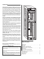
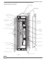
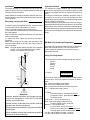
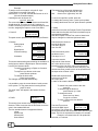
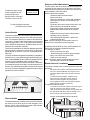
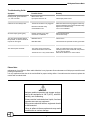
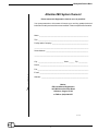
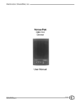
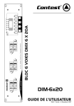
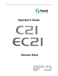
MX System Dimmer Bank
EDI
MX System Dimmer Bank
Users Manual
June, 1998 REV.11/99z
070-0700
©1998, Electronics Diversified, Inc.
1
Introduction
This manual is to accompany the MX series dimmer rack
by Electronics Diversified Inc. We believe you will find
our equipment reliable and well suited to your purpose.
In the next few pages we will be giving you further
information about the operation and maintenance of the
MX series dimmer rack. As always, our local representatives will be very pleased to help you. If you need
further information or assistance, you may be directed to
our factory technical and sales staff. Our Hillsboro factory number is noted below and at the back of this book.
The MX
This rack is designed to accommodate the MX series
dimmer modules. There are several different modules.
The difference lies primarily in the functional characteristics of the particular module. You may find it useful to
inspect the rack to determine which type(s) of modules
are being employed.
There are three sizes of two dimmers per module MX
series dimmer rack, the quarter size, the half and the
standard. Operationally they are identical.
At the top of each rack is a window giving some functional
information about the rack. Part of this are two LEDs
indicating the status, that is; one which indicates everything is okay, the other means there is some problem
within that particular rack.
Just below this is the Multi Link Intelligent Control
Module.Stacked down from this unit are the dimmer
modules. Note there may be more than one type of
module in your rack.
Behind and to either side of the modules are the electrical connections, the busses. These last are likely to be
electrically charged at high voltage, please exercise
caution.
You will find more detailed information about your rack
in the specifications materials and also in the Installation
Manual. For the purposes of normal operation and maintenance we provide the information contained in this
Users Manual.
MX
MX 1
UFD 2
MX 1
UFD 2
MX 1
D2 2
MX 1
D2 2
Table of Contents
EDI 24 hour Service / Support Network.
For technical questions or operational assistance please call
Customer Service at:
1-800-547-2690
This User's Manual is supplied with your MX Dimmer Bank. Copies
of this manual may be obtained from Electronics Diversified, Inc. for
a nominal charge.
Copyright 1998, by Electronics Diversified, Inc. All rights reserved.
Revised 12/99.
No part of this Manual may be reproduced by any means, graphic,
electronic, or mechanical, including photocopying, recording, taping,
or information storage and retrieval systems, without the express
written permission of Electronics Diversified.
Introduction . . . . . . . . . . . . . . . . . . . . . . . . . . . . . . . . 2
Illustration . . . . . . . . . . . . . . . . . . . . . . . . . . . . . . . . . 3
Installation, Door Removal
Operational Note, Programmer . . . . . . . . . . . . . . . . . . 4
Programmer . . . . . . . . . . . . . . . . . . . . . . . . . . . . . . . . 5
Control Module, Dimmer/Rack
Maintenance, Dimmer Removal. . . . . . . . . . . . . . . . . 6
Troubleshooting. . . . . . . . . . . . . . . . . . . . . . . . . . . . . . 7
Parts, Service . . . . . . . . . . . . . . . . . . . . . . . . . . . . . . . .8
Registration . . . . . . . . . . . . . . . . . . . . . . . . . . . . . . . . 9
MX System Dimmer Bank
MX Dimmer Bank Isometric Diagram
LOCATION OF FANS
KEEP CLEAR
POSSIBLE FEEDER
CABLE LOCATIONS
STATUS INDICATORS
(BEACON)
DOOR HINGE
TEST DMX2 INPUT
(CONTROL DESK)
MX 1
D2 2
MX 1
D2 2
HAND HELD
PROGRAMMER
CONNECTION
CONTROL MODULE
DIMMER MODULE
MODULAR SHELVES
CONTROL
INTERFACE
BOARD
AIR FILTERS
NEUTRAL BUSS
BACK MAINS BUSS
GROUND BUSS
CONVENIENCE OUTLETS
and
CIRCUIT BREAKER
MAINS BUSS
DOOR HINGE
SIDE PANEL
NOTE: Drawing not to scale
WELDED STEEL FRAME
Fig.1
3
Installation
Operational Notes:
For proper operation, the racks must be level, plumb and
square. If the rack is not level it will be difficult to install and
remove the dimmer modules.
The modules are easily installed and removed without
tools. Since it is possible you have different types or rated
modules, we suggest the rack be closed and locked at all
times.
It is likely the modules are installed in a specific order to
correspond to the wiring of the rack. Keeping the door
closed and locked may prevent the modules being moved
without reference to this order.
The cooling efficiency of the rack may be seriously compromised by the door being left open or removed, or by unfilled
dimmer slots. If this results in a dimmer(s) overheating, the
affected dimmer(s) will shut down and not operate until the
temperature has dropped to the operational temperature
range.
Racks should be securely mounted to the floor and to the
wall if necessary. Holes are provided in the floor of the rack
for this purpose.
Removing / hanging the Door
The door is easily removed and re-hung. It may be useful
to remove the door for maintenance or service.
A key is required to operate the cam-style locks.
To remove the door, lift the entire door up so the lower hinge
pin is disengaged.
Angle the door out at the bottom and allow it to drop down
off the top hinge pin.
To replace the door, follow the reverse of the above
procedure.
Notice the top hinge pin is longer than the bottom, the
sequence noted above is the only easy way to hang or
remove the door.
Note: The door latches operate only with a key supplied
by EDI. If You need replacement keys, please
contact our Customer Service Dept.
MX Multi-Link Hand-held Programmer
The hand-held, sometimes called "Remote" programmer
ships with each MX system. This unit plugs into the
control module and provides user access to the programmable features.
Using The Programmer
Lift top
in first
There are five Screens accessible through the Remote:
Patch A
Patch B
Backup
Profile
Setup
1. Patch A
Then swing
bottom in
and let down
WARNING:
Maximum ambient operation and storage environment for this equipment is 104°F (40°C), with 90%
humidity, non-condensing.
Extreme caution is advised when liquids, food and
cigarettes are near any equipment.
During severe electrical storms, equipment should be
disconnected.
Failure to adhere to these requirements may result in
malfunction or serious damage.
Patch A* Dim.01
IN1:001 IN2.001
The function of this screen is to assign the DMX address
for each input. This can be done on a dimmer by dimmer
basis.
IN1 refers to the DMX1 board output.
IN2 refers to the DMX2 board output.
Dim. is followed by the dimmer number in the rack.
The "*" indicates the patch is active.
To Patch:
To activate Patch A: press Patch A twice.
To change Dimmer: press Dimmer up/ down.
To change values:
Look for the ":", this is the Active Input.
Type in the value using the Number Keys.
To switch editing to IN2: press IN2.
Note the ":" has moved to IN2.
To Clear Patch: press Clear twice.
To Set a one to one Patch: press Unity twice.
To assign patch by one number steps:
For IN1, and the dimmer number: press S1.
For IN2, and the dimmer number: press S2.
MX System Dimmer Bank
Example:
To assign a one to one patch, using the S- keys:
Clear patch by pressing Clear twice.
Note that the ":" is on IN1, and that the Dimmer is on 01.
(See the illustration above)
If starting the rack at dimmer 97:
type 097, press S1.
The screen should now show the dimmer as 02 and IN1
should show 98. The value of 97 @ 1 has been recorded. Continuing to press S1 will step through the rack
in order, assigning the input on a one to one basis.
2. Patch B
:
The bottom line of the screen indicates the:
incoming value (left side) of 0-255
and:
dimmer level (right side) at 0-255.
To move from profile to profile: press S2.
To change the incoming value: press Level up/down.
To change the dimmer level out: press Dimmer up/down.
5. Setup
In this set of screens, the Preheat, Profile, Proportional
Patch and Non-dim and Hold Time information may be
accessed and modified.
With the exception of Hold Time, each of these items
may be changed on a dimmer by dimmer basis.
Patch B* Dim.01
IN1:001 IN2.001
This patch screen operates in the same way as Patch A.
3. Backup
Analog Inputs
( 0-10vdc )
BACKUP Analog 01
Dim01:000
Digital Inputs
Closed contact(s)
BACKUP Digital01
Dim01:000
Constants
BACKUP Constant
Dim01:000
SETUP Dim.01
Preheat: 000
Profile sets which profile
the dimmer uses.
The range is 1 to 7.
SETUP Dim.01
Profile: 000
Proportion sets the
SETUP Dim.01
output level of the dimmer
Proportion: 000
as a value which is some
proportion of the 0 to 100% value of the input level.
Example: If the value is set to 204 (80%), the
dimmer actual out put will be 80% of the possible total,
the input value will show 100%.
This screen allows editing and recording the available 12
analog inputs, and the 4 digital inputs. Also accessible
here are the constant values.
To switch from Analog, to Digital, to Constant:
press S2.
To step from one dimmer to the next:
press Dimmer up/down.
To change the level value:
press Level up/down.
The changes are recorded automatically.
Nondim will set the dimmer
SETUP Dim.01
to turn on or off at the
Nondim: 000
50% input value.
A value of 001 sets the dimmer to nondim.
It is possible to copy the current dimmer levels present
in the system. To copy these active incoming values:
press S1 twice.
The word "save" will appear in the bottom left of the
screen.
4. Profile
Preheat sets the minimum
level of the dimmer.
The value range is
from 0 to 255.
To switch from each screen to the next:
press S2.
To step through the dimmers:
press Dimmer up / down.
To change the value:
press Level up / down,
or type in a number.
To copy a value to the next dimmer:
press S1.
PROFILE 1
Lev.000:000
This screen gives access to the output profiles of the
dimmers. There are seven slots in this screen, three are
open in the standard MX rack.
The four standard slots are assigned as follows:
Linear
Square Law
Advance MX
User defined
The Hold Time screen
SETUP * 3 sec
access the DMX signal
Hold Time : 100
processing. This screen sets
the time the dimmer will hold a DMX value after the input
stops. The time is expressed in multiples of 3 seconds.
Example: An entered value of 100 equals 300
seconds, or 5 minutes.
5
Dimmer and Rack Maintenance
The dimmer check screen
makes it possible to step
through the dimmers,
bringing each to full output.
The value of up full is 225.
SETUP Dim. 01
Dimmer Check
To step through the dimmers:
press Dimmer up / down.
Control Module
The control module is the user interface with the electronic
brain and monitoring features of the MX series dimmer
rack. The illustration shows the location of the DMX input
connection, ( a control cable from a lighting control board
may be plugged here ). Also, to the right is the connection
for the hand-held programmer. Between these are LED
indicators of internal rack functions.
These function indicators are limited to displaying the most
basic presence or absence of the electrical or electronic
signal named on the face of the rack immediately below
each LED.
The only LED that when lighted is an indication of a problem
with the rack, or, more specifically with the dimmer(s) in the
rack, is labeled Fault. All other LEDs are lighted when the
function named is activated under normal operation.
Also in the area of the LEDs is a service switch. This switch
is recessed and requires the aid of a small pointed tool to
activate. This switch allows for all the dimmers to be turned
to full-up. The switch essentially bypasses all other control
signals to the control module.
The MX system, like all electrical / electronic equipment
is affected by the presence of dirt and dust. We recommend the rack be opened, the modules removed and all
items cleaned to remove this dust.
Pleases follow this procedure:
•Shutdown and Disconnect Power.
•Remove the door.
•Remove each dimmer module and individually
clean either by vacuum or low pressure com
pressed air.
•Clean the other interior areas of the rack in the
same manner as the individual modules.
•Inspect the internal connections of the main
feeders and of the branches to the module
plugs.
•Inspect the connector ends for discoloration
indicating a poor connection.
•After cleaning and inspection, replace the
modules and the door.
Note: Annual cleaning is recommended, more frequently if the environment is particularly dirty.
To help prevent the build up of dirt, the Electrostatic Air
Filters may be cleaned or replaced frequently.
To clean the Air filters:
•Remove air filters from door.
• Wash with a light to medium pressure water
spray. Use cold to luke-warm water.
• Allow to dry and replace.
Note: The filter(s) must be replaced with the correct
side facing the interior of the cabinet.
Dimmer Removal / Installation
To remove a dimmer from an MX rack please follow this
procedure:
•Be certain of the position of the Dimmer Module to be
removed. Locate this Module by using the Circuit
numbering label located to the left of the dimmers
(Ck #_ ).
•Locate the Circuit Breakers - Switches to the
left on the face of the Module to be removed.
•Move the switch toggles to the OFF position.
•Firmly grasp the top lip of the Module and pull the
Module directly out of the module bay.
e
rvi
c
Se
ult
C
Fa
Ø
Ø
B
2
ØA
X
DM
DM
X
1
To replace a dimmer module:
•Locate the correct circuit numbers, note there may be
a pair of circuits per each dimmer module.
•After carefully lining up the sides of the modules with
the appropriate shelf slots, slide the module in very
firmly to assure solid connections are made.
DO NOT SLAM MODULES INTO THE RACK!
Dimmer Module
The standard dimmer modules provide one LED indicator
per dimmer circuit which gives a visual indication of the
dimmer activity. Also provided is another LED indicator
which warns of a fault in that module.
MX 1
D2 2
MX System Dimmer Bank
Troubleshooting Guide
Symptom
Possible Cause
Remedy
Nothing works, green indicators
1, 2, and 3 are dark.
Blown fuse in rack
Input power source is off.
Check input power source.
A dimmer circuit is always OFF.
The dimmer module is not plugged in.
Defective solid-state relay.
Circuit Breaker is off.
Make sure dimmer is firmly plugged in all the way.
Check control wiring connector to solid state relays.
Replace the solid-state relay.
Turn on circuit breaker.
All of the lamps "ghost" (glow).
Dimmer preheat set too high.
Control out of calibration.
Reduce preheat level.
Contact the factory.
The dmx signal indicator flashes,
lamps flicker, or dimmers refuse to
respond to dmx signal.
Bad DMX source.
Check source.
Bad DMX cable.
Check the dimmer pack with a known good cable.
The dimmer pack overheats.
The cooling vents are blocked.
The dimmer module is full of dust.
Clear any obstructions to the cooling vents.
Carefully remove dust and dirt with compressed
air or a vacuum cleaner.
Relocate the dimmer to a cooler location.
The dimmer is in a very warm location.
Please Note:
Maintenance of your Dimmer Rack and the Modules is very Important. Such maintenance will help to prevent failure and
prolong component life.
It is very important all the slots in the rack be filled for proper cooling airflow. If a module must be removed, replace the
module with a module blank.
WARNING:
Maximum ambient operation and storage environment for this equipment is 104°F (40°C), with 90%
humidity, non-condensing.
Extreme caution is advised when liquids, food and
cigarettes are near any equipment.
During severe electrical storms, equipment should
be disconnected.
Failure to adhere to these requirements may result
in malfunction or serious damage.
7
Replacement Parts
Replacement parts are available from Electronics Diversified, Inc.
To obtain replacement parts, call (800) 547-2690 and
ask for Customer Service.
Since these systems are customized for individual
applications, it is important that you have the following information available when you call.
The equipment type or number
Serial number
Original EDI system drawing number
(As-Built Drawing Number)
Please SPECIFY LINE VOLTAGE.
When calling, the customer service representative
will help to determine the proper part you need, and
any additional parts, if necessary, depending upon
your requirement.
Service
EDI 24 hour Service / Support Network.
For technical questions about this product or
operational assistance contact Customer Service at: . . . . . . . . . .. . . . . . . . .1-800-547-2690 or 1-503-645-5533
You may communicate by FAX: . . . . . . . . . . . . . . . . . . . . . . . . . . . . . . . . . . . . . . . . . . . . . . . . . . 1-503-629-9877
Internet: . . . . . . . . . . . . . . . . . . . . . . . . . . . . . . . . . . . . . . . . . . . . . . . . . . . . . . . . . . . . . . . . . . . . . . . . . . . . . . www.EDIonline.com
Internet E-Mail: . . . . . . . . . . . . . . . . . . . . . . . . . . . . . . . . . . . . . . . . . . . . . . . . . . . . . . . . . . . . . . . [email protected]
If your Mark X Dimmer Bank needs repair, call 503-645-5533 for a Return Materials Authorization number.
At that time you will be given a shipping address .
This is a product of:
1675 N.W. Cornelius Pass Road, Hillsboro, Oregon 97124 USA
MX System Dimmer Bank
Attention MX System Owners!
Please return this Registration Card As soon as possible!
Your prompt attention to this matter will ensure your receiving updated technical
information for this product as it becomes available. Please complete all information.
Name: _______________________________________________________
Title: ________________________________________________________
Facility and/or Company: ________________________________________
_____________________________________________________________
Street Address: _______________________________________________
_____________________________________________________________
City: ____________________________ State: ______ Zip: __________
Phone: ______________________________________________________
Fax: _________________________________________________________
Web site: ____________________________________________________
Mail to:
EDI User Manual Registration
1675 NW Cornelius Pass Road
Hillsboro, Oregon 97124
!
CUT ALONG DOTTED LINE
E-mail: ______________________________________________________
or FAX to: (503) 629-9877
Rev12/99z
9