1
TURNKEY PRINTING SOLUTIONS
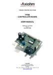
TPSK PRINTER SERIES
24 & 12V
USER MANUAL
Reference 3107118 Issue A
November 2004
AXIOHM
1, rue d'Arcueil, BP 820
92542 MONTROUGE CEDEX
FRANCE
Tel : (33) 1 58 07 17 17, Fax : (33) 1 58 07 17 18
www.axiohm.com
EVOLUTIONS
Date
05/02
Issue
Preliminary
Modifications
10/02
Z
Creation
11/04
A
Addition of TPSK 12V version
TPSK Printer Series User Manual
Page 1 / 21
Reference: FDE – 3107118 Issue A
INTRODUCTION
The TPSK series is part of the "Compact Kiosk" printer family. The wide range of temperature and
humidity operating conditions allows integration to a system used indoors or outdoors.
The TPSK printers are turnkey units that contain the printing head, the interface controller board, the
paper roll bucket and a cutter / paper chute assembly to protect and display the printed ticket.
The main characteristics are:
Easy connection (12V or 24V power supply and serial interface)
Easy paper loading with a font printer door, a bucket to set the roll of paper, and a “Clamshell” system
to easily set the paper under the print head.
Different ways to install the printer, including a possible sliding system for sealing.
Compact size in which 4 inch paper rolls can be used.
Many information sent back to the host system such as : jam, low paper, out of paper …
A specific cutter patented by Axiohm with which the ticket can be cut when the user pulls it.
This protects the ticket in a chute while it is printed. The chute on the existing units is optimized for a 4
inch ticket length.
Please contact Axiohm for other needs.
Based on the TPSK mechanical & hardware design, the firmware can be customized to fit many
applications. If needed, please contact Axiohm Representatives.
TPSK Printer Series User Manual
Page 2 / 21
Reference: FDE – 3107118 Issue A
CONTENTS
1 TECHNICAL SPECIFICATIONS .......................................................4
2 INTERFACE BOARD FEATURES .....................................................5
2.1
Overview: ............................................................................................................5
2.2
Baud Rate setting for RS232 communication ..................................................6
2.3
Serial HE10 Pinout .............................................................................................6
2.4
Available Control Codes ....................................................................................7
2.4.1
Control codes ......................................................................................7
2.4.2
Command description format .............................................................7
2.4.3
Print Features ......................................................................................7
2.4.4
Motor Brake Command ......................................................................8
2.4.5
Graphic Printing..................................................................................9
2.4.6
Full Graphic Printing Commands .......................................................9
2.4.7
Paper Management ...........................................................................11
2.4.8
Additional and Optional Features .....................................................12
2.4.9
Character sets....................................................................................13
2.4.10
Status ................................................................................................14
3 MECHANICAL FEATURES..............................................................15
3.1
External Dimensions.........................................................................................15
3.2
Housing features for ticket access ...................................................................17
3.3
Paper Loading...................................................................................................17
3.4
CUTTER SYSTEM / PAPER CHUTE...........................................................19
4 RECOMMENDATIONS .....................................................................20
4.1
Storage :.............................................................................................................20
4.2
Duty cycle : ........................................................................................................20
4.3
Grounding : .......................................................................................................20
4.4
Print head Cleaning : .......................................................................................20
4.5
Ticket access / Housing features......................................................................20
4.6
Power supply .....................................................................................................20
5 TROUBLESHOOTING .......................................................................20
TPSK Printer Series User Manual
Page 3 / 21
Reference: FDE – 3107118 Issue A
1
TECHNICAL SPECIFICATIONS
The following table gathers the main characteristics of the printing unit.
ITEM
Printing method
Paper loading
Number of resistor dots
Resolution
Printing width
Printing speed
Paper width
Head T° detection
Paper feed pitch
Paper empty detection
Operating voltage range Vcc
(logic)
Vch (dot)
12 V Version
24 V Version
Static thermal dot line Static thermal dot line
printing
printing
Clamshell
Clamshell
384
384
8 horizontal &
8 horizontal &
vertical
vertical
48
48
100
100
+0.1
+0.1
60
60
-1
-1
By Thermistor
By Thermistor
1
1
0.125
0.125
Opto-sensor
Opto-sensor
4.75-5.25
4.75-5.25
Current Consumption : Vch
Current Consumption: Vcc
(all dots "on")
Nominal dot energy (High
sensitivity paper)
Current Consumption: Stepping
motor
Current Consumption: interface
board
Stand-by 24V
Peak print head current
(all dots ”on ” at nominal
value)
Over all dimensions:
Width
Depth
Height
Weight
Storage range*2
Relative humidity*2
Operating range*2
Electrical lifetime *3
Mechanical lifetime *3
UNIT
--dots
Dots/mm
mm
mm/s
mm
-Motor steps
mm
-V DC
10.8-13.2
(max 16 stand by)
28
20 - 26.4
(max. 30 stand by)
22.6
V DC
42
42
mA
0.34*1
0.32*1
mJ
300
300
80
40
mA per activated phase
at nominal voltage
mA
8.8
8.8
A
102
160,5
204,37
1700
-20 to +85
20 to 90
no condensing
0 to +60
108
50
102
160,5
204,37
1700
-20 to +85
20 to 90
no condensing
0 to +60
108
50
mm
mm
mm
g
°C
%
mA per resistor dot
"on" at nominal voltage
°C
pulses on OE signal
km
*1 In standard conditions: Nominal Volts, 25°C, for a print head with a resistance of 1000 Ω (24V) or
480 Ω (12V), at 800 PPS
*2 Contact Axiohm for recommendations if extended conditions are required
*3 Per AXIOHM conditions
TPSK Printer Series User Manual
Page 4 / 21
Reference: FDE – 3107118 Issue A
2
INTERFACE BOARD FEATURES
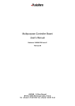
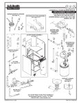
2.1 Overview:
Printer connections are
available directly on the board
connectors at the printer rear.
The power supply must be a
switch power supply AC/DC 24V 3A mean, with minimum
recommended power 75VA
(possible peak of 8.8A during
1.5ms).
or 12V 6A mean with minimum
recommended power 75VA
(possible peak of 8.8A during
1.5ms).
The communication is serial
RS232 with possible baud rate
setting as described below.
TPSK Printer Series User Manual
Page 5 / 21
Reference: FDE – 3107118 Issue A
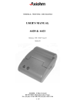
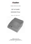
2.2 Baud Rate setting for RS232 communication
If there is no jumper the RS 232 communication baud rate is 230 k Baud.
With one (or two) jumper, the baud rate can be set as described in the following table:
0
0
0
1
1
38,4 K baud 115,2 K baud
0
192 K baud
1
1
230.4 K baud
The default baud rate setting for TPSK is 115.2 K baud.
Important Note: in addition to the jumper setting, the printer must be reset to change the baud rate. The
baud rate can then be checked on the self-test ticket.
Jumper setting area
Power Connection
Serial HE10
communication
-
-
- + NC +
Note: All connectors should be SELV types in order to safety standards (Safety extra low voltage).
2.3 Serial HE10 Pinout
Pinout Description
HE10 (board side)
1:
2:
3:
4:
5:
6:
7:
8:
9:
GND
TXD
GND
RXD
NC
NC
DSR
GND
DTR
Recommended Connector
HE10: 10 points with locating and holding clips
3M ref.: 89110-0103HA or equivalent
TPSK Printer Series User Manual
Page 6 / 21
Reference: FDE – 3107118 Issue A
Mis en forme : Police :Times
New Roman, 11 pt
2.4 Available Control Codes
2.4.1
Control codes
Control codes are non-printable characters or sequences of characters, which subsequently affect the
printer operation.
For your convenience, these are grouped below in logical sets of commands.
2.4.2
Command description format
Throughout the following descriptions of the commands you will note that two special codes are used to
cause the printer to interpret the following byte or byte as part of a command and not as printable
characters. These codes are:
Code
ESC
GS
Name
Escape
Graphic Sequence
Dec. Value
27
29
Hex. value
1B
1D
General “escape sequence” commands
Often used for special graphic commands
The general command syntax is as follows:
Command
(Description)
(Format)
(Comment)
2.4.3
Name and description of the command.
The code sequence to be sent to the printer.
<nn> is used to represent the decimal value used for the command.
<nnH> is used to represent the hexadecimal value used for the command.
<ndata> is the raw data used to create graphics and bar codes.
Additional information such as range allowed for the numbers or default
values.
Print Features
CODE
<0AH>
<13H> Line Feed
<0BH><nline>
Vertical tabulation: Feeds <nline> lines and goes to the beginning of
the line
Carriage return
Double Width: Selects double width character printing
End of double width
General Font Reset.
Note: It is recommended not to use 10H to return the Command Codes
to the default values, but instead use the corresponding control codes.
Example: 0FH to cancel 0EH
Double Height : Selects double height character printing
End of double height
Underlining : Selects underlined character printing
End of underlined printing
Inverse Video : Selects white on black printing
Note: inverse video printing may have an impact on the printing speed
due to the high number of dots lighted per printing line.
End of Inverse Video
<0DH>
<0EH>
<0FH>
<10H>
<12H>
<13H>
<15H>
<18H>
<1EH>
<1FH>
TPSK Printer Series User Manual
Page 7 / 21
Reference: FDE – 3107118 Issue A
2.4.4
Motor Brake Command
ESC'm'
Puts the motor into brake mode, with a 30 seconds time out.
Print Directions
GS'I'<n>
Normal printing if n=0, 180 deg. printing if n=1.
Bar Code
GS'A'<n1><n2>
Selects X position of bar code (X>0):
X=n1*256+n2 (Default value = 64)
GS'w' <mag>
Select horizontal size (magnification) of bar code
mag = number of dots per thin bar.
The ratio between thin and thick bar is 2.
If you need a different ratio use GS'W' code
GS'W' <nthin> <nthick>
Select the width of the thin and thick bar in dots.
(Default value = 1,3)
GS'h'<nheight>
Selects height of bar code.
Height = height in dot lines. 1<N<255. (Default value = 120)
GS't'<under>
Writes text under the bar code if under = 1
(available only with vertical bar code).
Do not write if under = 0 (default value).
Note: Command not available in code 128
GS'O'<or>
Bar code orientation
Or = 0 : Vertical bar code (default value).
Or = 1 : Side printed bar code (ladder bar code)
GS'k'<type><X><data 1>...<dataN>
Selects a bar code generator and prints the bar code.
X = number of characters to be printed.
type
bar code
2
EAN 13
3
EAN 8
4
Code 39
6
Codabar / Monarch
7
Interleaved 2/5
8
Code 128 A
9
Code 128 B
10
Code 128 C
Bar codes can be printed vertically or horizontally, by using the GS'O'<or> command. It is impossible to
print any information at the end of the bars when you are in ladder bar code mode.
The printer will therefore only print the character sent when using a barcode with check-sum.
This information is sent by the user and not calculated by the printer.
TPSK Printer Series User Manual
Page 8 / 21
Reference: FDE – 3107118 Issue A
2.4.5
Graphic Printing
<11H> <data1>,....,<data 24>
Graphic mode. The following 1 to 24 data byte are 8*2 bit bitmap data
to be printed on a line.
To be compatible with the last printer, each byte generates 16 dots:
every dot will be repeated.
GS <FEH> <XXH…XXH>
Enters in Full Graphic Mode
2.4.6
Full Graphic Printing Commands
GS <FEH>
Enters in full graphic mode
<00nn nnnnb><List of graphic byte>
Mode without compression (bit 6=0 and bit7=0), and number of
uncompress byte (bit 0 to 5: N). Follow the list of uncompress byte.
<11nn nnnnb><Pattern Byte>
Mode with compression (bit 6=1 and bit 7=1), and number (bit 0 to 5:
N) of <Pattern Byte>.
If N equals 00 0000b then end the line with white dots.
If N equals 11 1111b, then end the line with black dots.
<10nn nnnnb>
Repeat Mode: This mode gives how many times (bit 0 to 5: N times) the
next line will be repeated. 63 repeat can be managed.
After this command a line has to be described.
<01xx xxxxb>
End of Full Graphic Mode (bit 0 to bit 5 not used).
(See diagram on next page)
TPSK Printer Series User Manual
Page 9 / 21
Reference: FDE – 3107118 Issue A
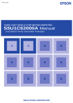
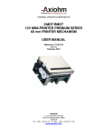
GS <FEH> Full Graphic Mode
Full Graphic
Sub
Full Graphic
Sub Command
Command
<01xx xxxxb>
End of Full Graphic Mode
<10 nn nnnnb>
Repeat next line
<00nn nnnnb>
Mode without
compression.
N byte pattern:
uncompress data.
<11nn nnnnb>
Mode with compression
N+1 Number of repeat
lines (up to 64 repeats)
N number of
pattern byte
N=00 0000b,
then end line
with white dots
N=11 1111b, then
end line with
black dots
<Pattern Byte>
NO
Number of 30H
byte for one
graphic line of
reach?
YES
Goto Full Graphic Sub Command
Algorithm for the GS FE control code
TPSK Printer Series User Manual
Page 10 / 21
Reference: FDE – 3107118 Issue A
EXAMPLES
1) To print a 5 Grey Line:
GS <FEH><84H><1111 0000b><AAH><40H>
2) To print a half black line:
GS<FEH><1101 1000><00H><1111 1111><40H>
3) To Print 100 white lines:
GS<FEH><1011 1111b><C0H><10100101b><C0H><40H>
3) To print a line without compression, and the same line with compression:
Aim: print 3* <16H>, 2*<18H>, 2* <10H> and end line with white dots.
We have twelve byte, if uncompress method:
GS<FEH><0000 0111b><16H><16H><16H><18H><18H><10H><10H><1100 0000b><40H>
We have 10 sequences of <pattern byte>
GS<FEH><1100 0011b><16H><1100 0010b><18H><1100 0011b><10H><1100 0000b><40H>
Notes:
1) If you have less than 2 similar byte for a graphic line, prefer the non-compression subcommand.
2) You can mix compression and non-compression command for the same line.
Ex: To print 3 similar byte and black remaining line
GS<FEH><0000 0011b><16H><16H><16H><<1100 0000b><40H>
3) During all compression mode, you must not send ESC’v’ OR ESC’P’ OR ESC’W’ sequence. These
control codes are real time interpreted, consequently these codes will be manage during a graphic
compression data flow.
2.4.7
Paper Management
ESC'J' <n ¼mm>
Forward feeds n ¼mm (0<n<255) and goes to the beginning of the line.
ESC'I'
Resets buffer, executed in real time.
TPSK Printer Series User Manual
Page 11 / 21
Reference: FDE – 3107118 Issue A
2.4.8
Additional and Optional Features
Selects the character set of the country. (default value: 0)
ESC'R'<nset>
nset
0
1
2
3
4
5
6
7
8
9
10
n
Country
0
1
2
3
4
5
6
7
8
9
10
U.S.A.
France
Germany
UK.
Denmark I
Sweden
Italy
Spain
Japan
Norway
Denmark II
Country
USA
France
Germany
UK
Denmark I
Sweden
Italy
Spain
Japan
Norway
Denmark II
Ascii Character Code
23h 24h 40h 5Bh 5Ch 5Dh 5Eh 60h 7Bh 7Ch 7Dh 7Eh
35 36 64 91 92 93 94 96 123 124 125 126
#
#
#
£
#
#
#
Pt
#
#
#
$
$
$
$
$
¤
$
$
$
¤
$
TPSK Printer Series User Manual
@
à
§
@
@
É
@
@
@
É
É
[
•
Ä
[
Æ
Ä
•
¡
[
Æ
Æ
\
ç
Ö
\
Ø
Ö
\
Ñ
¥
Ø
Ø
]
§
Ü
]
Å
Å
é
¿
]
Å
Å
Page 12 / 21
^
^
^
^
^
Ü
^
^
^
Ü
Ü
`
`
`
`
`
é
ù
`
`
é
é
{
é
ä
{
æ
ä
à
¨
{
æ
æ
|
ù
ö
|
ø
ö
ò
ñ
|
ø
ø
}
è
ü
}
å
å
è
}
}
å
å
~
¨
ß
~
~
ü
ì
~
~
ü
ü
Reference: FDE – 3107118 Issue A
2.4.9
00
Character sets
10
0
01
16
11
1
02
13
3
4
5
06
16
6
22
7
08
1B
11
0C
27
12
0E
0F
1F
15
45
.
46
31
<
60
/
47
69
=
61
F
70
G
71
H
72
62
?
73
67
W
J
74
X
88
6A
[
91
\
76
M
]
77
5E
94
5F
79
_
z
8B
{
|
8D
141
8E
~
126
7F
142
127
153
Å
143
166
º
167
Ü
154
168
⌐
¬
170
½
171
172
¡
173
174
AF
ƒ
159
╣
CA
║
CE
175
╬
190
CF
┐
191
207
²
237
221
EE
254
238
222
FF
EF
223
253
FE
ϖ
▐
▀
252
FD
ED
DF
╧
ν
▌
206
251
236
220
DE
√
FC
EC
▬
205
250
FB
235
219
DD
═
189
╛
█
204
CD
╜
EB
DC
╠
188
234
218
203
CC
╝
┌
249
FA
EA
DB
╦
187
233
217
202
CB
╗
┘
248
F9
E9
DA
╩
186
BF
»
201
247
F8
232
216
D9
╔
185
E8
╪
200
C9
BE
«
╚
184
BD
AE
158
╕
231
215
D8
246
F7
E7
╫
199
C8
230
214
D7
╟
183
BC
¼
157
Pt
╖
BB
AD
¥
C7
245
F6
E6
╓
198
244
F5
229
213
D6
╞
182
BA
AC
156
╢
169
155
£
C6
E5
╒
197
243
F4
228
212
D5
┼
181
B9
AB
¢
╡
E4
╘
196
C5
B8
¿
─
227
211
D4
242
F3
E3
╙
195
180
B7
AA
9F
8F
≅
Ö
9E
Ä
ª
A9
9D
ì
125
7E
111
140
}
109
152
9C
î
124
m
o
139
8C
7D
ÿ
┤
B6
A8
9B
ï
123
108
110
138
165
151
9A
è
122
l
6F
95
8A
7C
n
137
Ñ
├
226
210
D3
241
F2
E2
╥
194
C4
B5
A7
99
ë
121
107
6E
^
y
7B
6D
93
89
164
ù
136
B4
ñ
150
98
179
163
┬
240
F1
225
209
D2
C3
|
ú
û
ê
120
k
92
5D
x
106
6C
L
88
7A
6B
135
B3
A6
97
ç
119
j
90
5C
O
105
Z
75
87
79
i
134
w
104
89
96
å
118
149
178
162
A5
ò
133
v
h
Y
95
86
78
69
K
78
103
68
5B
N
g
87
148
C2
E1
╤
193
F0
224
208
D1
┴
177
E0
╨
192
C1
▒
ó
D0
└
176
B2
A4
ö
à
117
77
147
132
161
A3
ô
ä
u
102
146
94
85
i
A2
Æ
C0
░
B1
145
131
116
160
A1
93
84
B0
á
æ
â
t
f
86
130
115
76
V
5A
4F
63
66
144
92
é
s
75
101
129
83
100
e
ü
114
99
A0
É
91
r
d
85
128
82
74
U
59
I
c
65
58
113
73
64
84
q
98
83
90
Ç
81
b
S
T
112
72
63
57
4E
>
82
56
4D
3F
2F
E
97
62
R
80
p
71
a
81
55
4C
3E
2E
30
59
3D
-
68
4A
3C
44
D
57
58
Q
54
4B
;
43
29
14
:
+
2D
1E
9
3B
,
67
49
42
2C
1D
56
3A
*
28
13
41
2B
1C
0D
)
C
96
61
53
48
8
40
2A
26
55
39
25
10
0B
(
29
1A
0A
7
39
66
47
38
24
9
54
37
'
B
70
`
80
52
46
6
38
28
19
53
30
&
65
45
5
37
23
8
52
35
%
A
44
4
36
27
18
09
$
26
17
07
34
25
21
51
60
P
51
43
3
35
24
15
50
33
#
64
42
2
34
20
49
32
"
50
@
41
1
33
23
14
05
!
19
48
31
22
18
40
0
32
17
2
04
SP
21
12
03
30
20
BLANK
239
Note : From E0 to FA, the characters are issued from the font ISO 8859-8 (Hebrew Font)
TPSK Printer Series User Manual
Page 13 / 21
Reference: FDE – 3107118 Issue A
255
2.4.10 Status
The printer status is returned after the reception of the ESC sequence.
Two different types of status are available:
• With Esc'v', the printer returns the status of each sensor.
• With Esc'P' it returns the interpretation of this status (for instance if the
cutter sensor is positioned low at the end of the cut it will respond “jam”).
ESC'P'
Ask for printer status (MSB bit 7, LSB bit 0)
Bit Number
0
Description
Fatal Jam
1
2
3
Print head Resolution
End of Paper
Low Paper
4
5
6
7
Test Button
Power Failure
Buffer
Printer Clamshell door
ESC'v'
Bit Number
0
power failure / reset
empty
Door open
LOW = 0
OK
OK
switch lever closed
paper OK
always low
OK
contains data
Door closed
Ask for sensors and buttons status (MSB bit 7, LSB bit 0)
2
Description
End of Paper (optical
sensor)
Flap position (optical
sensor)
Low paper (switch)
3
4
5
6
7
Jam (opto)
Test Button
Forward Button
Pre-Heating
Power Failure
1
HIGH = 1
jam or flap open: printing
disabled
always high
no paper, printing disabled
switch lever open
low paper
HIGH = 1
paper present
LOW = 0
no paper
flap present (high position)
flap open (paper pulled
out from chute end)
switch lever open
low paper
no paper
always low
always low
disabled
OK
switch lever closed
paper OK
paper present
enabled
power failure
Note: To avoid information fluctuation
- “Paper low” is reported with a 50 seconds delay
- “Jam” is reported with a 6 seconds delay (paper feeding is stopped in real line).
ESC’W’
Firmware version. The printer responds with 4 byte (Ex: 0111).
The two first digits (byte 1 & 2) are for Major Revision (MR, ex: 0x00 & 0x01 for
01); the two last (byte 3 & 4), for minor Revision (mR, ex: 0x00 and 0x0B for 11).
Bits 0 to 3 of byte 1 code for MR/16 (int. div.), ex: 0x00.
Bits 0 to 3 of byte 2 code for MR%16 (modulo, reminder of integer division), ex:
0x01.
Bits 0 to 3 of byte 3 code for mR/16 (int. div.), ex: 0x00.
Bits 0 to 3 of byte 4 code for mR%16 (modulo, reminder of integer division), ex:
0x0B.
TPSK Printer Series User Manual
Page 14 / 21
Reference: FDE – 3107118 Issue A
3
MECHANICAL FEATURES
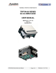
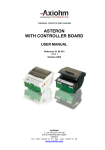
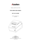
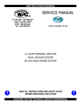
3.1 External Dimensions
TPSK Printer Series User Manual
Page 15 / 21
Reference: FDE – 3107118 Issue A
The support for this printer needs to be "U
shaped" to allow the paper roll bucket to
protrude through.
The printer can be either fixed (using a "U
shaped" support and the two holes
underneath the unit), or free to slide with its
guiding tabs (for sealing issue if needed).
TPSK Printer Series User Manual
Page 16 / 21
Reference: FDE – 3107118 Issue A
3.2 Housing features for ticket access
See section «Recommendations».
3.3 Paper Loading
The following steps are needed to load the paper:
Open the door by pulling it
Remove the core of the preceding roll if necessary
Place the new roll
Set the paper end through the door chute over the platen
Close the door, keeping the paper end tight to avoid a possible paper loop.
Pull the paper end to cut; it the paper is loaded.
TPSK Printer Series User Manual
Page 17 / 21
Reference: FDE – 3107118 Issue A
Maximum paper roll diameter is102 mm; "low paper" information will be sent with diameter lower than
40 mm.
Paper / roll width must be 59 to 60 mm.
TPSK Printer Series User Manual
Page 18 / 21
Reference: FDE – 3107118 Issue A
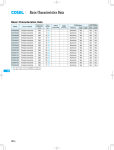
3.4 CUTTER SYSTEM / PAPER CHUTE
The paper is fed into a chute. The user can get the ticket end at the chute exit. The user then cuts the
receipt when he pulls on the ticket.
With this system (on existing units), the distance between the printing line and the cutting line is
between 20 and 21 mm. It is possible to print a header (or footer) of the next ticket in this area.
The chute hides the ticket from the user until it is fully printed; the length of ticket with the existing
TPSK is 4 inches. With tickets shorter than 3.75 inches, the user would not access the ticket end. It is
possible to print a ticket longer than 4 inches; sensors and software provide security to avoid jam when
the ticket is pulled during printing.
Chute length optimised
for 4 inch tickets:
- for ticket protection
- for ticket end access
TPSK Printer Series User Manual
Page 19 / 21
Reference: FDE – 3107118 Issue A
4
RECOMMENDATIONS
4.1 Storage :
If the printer has been stored for a long time with paper set below the print head, it may be
necessary to re-load the paper before operating.
4.2 Duty cycle :
If the temperature is between 50°C and 60°C: the duty cycle is 10% (10% ON, 90% Off), with a
maximum printing time of 10 seconds.
If the temperature is lower than 50°C: the duty cycle is 20%, with maximum printing time 10
seconds.
Higher duty cycle may destroy the paper feed motor.
Printing is stopped by of a software security feature, if the temperature of the print head becomes
too high. Printing will re-start after cooling.
4.3 Grounding :
The printer must be grounded. This can be done either by setting it on a grounded metal support
or by connecting its external chassis.
4.4 Print head Cleaning :
This printer is designed with the print head facing down, this avoid dust accumulation. However,
in heavy duty condition or if the paper used has a poor quality, it is recommended to clean the
print head. The print head is visible and accessible when the door is opened.
To clean the heating dots of the head, use a cotton stick containing a solvent alcohol (ethanol,
methanol, or IPA), but do not touch the print head with your fingers!
AXIOHM can provide cleaning kits, ref.: CK60000A
4.5 Ticket access / Housing features
To maintain printer reliability, the pressure on the Clamshell door must be limited. In case of
sealing needs, make sure the pressure applied to the door is lower than 6 lbs.
This pressure must be applied around the ticket exit chute.
Please contact Axiohm Technical Support for specific integration.
4.6 Power supply
The power supply should be 75 Watts or more, particularly if a heavy duty is requested by the
head (reverse video, wide black marks).
5
TROUBLESHOOTING
TPSK Printer Series User Manual
Page 20 / 21
Reference: FDE – 3107118 Issue A
Situation
Paper loading:
When the paper is
correctly loaded and the
printer is powered, closing
the door will generate a
self-test ticket with the
message
"PAPER
SUCCESSFULLY
LOADED".
Printing tickets:
Problem
The self-test ticket is not
printed.
Solution
Check if the printer is powered.
Check if the paper end is tight enough:
- Open the door.
- Keep the paper end tight from the chute
outlet.
- Close the door; printing of the self-test
should begin.
Printer prints blank tickets.
Make sure the paper roll is not set upside
down; see the instruction label inside the
printer.
Tickets do not come out:
Even though no error message
is sent.
Even though tickets are
required, and the printer
makes noise as if it was
printing.
Open the printer door.
Check if there is a small black plastic part
(paper guide) between the roller and the white
plastic flap.
This guide is clipped to the roller axle and
attached to the white flap; if it is missing,
there is a gap between the roller and the flap
in which the paper can be fed.*
Printer prints erratic
characters.
A wrong baud rate could be the cause:
Check if the jumper is in place (bottom right
of the PCB); refer to the chapter "Baud rate
setting" for the proper position in which to set
the jumper, to obtain the required baud rate.
The baud rate is indicated on the self-test
ticket, which can be printed by closing the
door.
Printer does not start printing, If your application can detect status return,
even though paper path is
check the sensor status.
clear and there is no visible
jam.
If your application does not detect the status
return, or you cannot easily check them:
Make sure that all sensors are plugged in
correctly
- Four connectors on the right side of the
PCB, from top to bottom:
4 contacts, 3 contacts, 2 contacts with red
wires, 2 contacts with black wires.
Check the door switch for contact (small
mushroom switch on the left of the printer
mechanism). When applying pressure to the
switch, it should make a noise; if it does not,
there is no contact and the switch may need to
be replaced.
* For replacement of this part, call maintenance.
TPSK Printer Series User Manual
Page 21 / 21
Reference: FDE – 3107118 Issue A