1
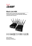
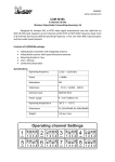
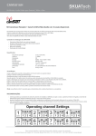
CAMSAT
www.camsat.com
CD06
Transmitter and receiver
This set is used for remote control (turn on/off) by means of any devices for long
distance. It uses the RS485 wire interface. The CD06-Rx receiver possesses six transmitters in
it, of the current load up to 4A each. The NO (normally open) contact points are directed to
the term block and the NC (normally closed) ones are directed to the transmitter. It is
possible to control outlets in the receiver by means of the CD06-Tx transmitter or the PTZ
keyboard. Devices possess the signalling system, by means of LED diodes, which shows the
state of inlets in the transmitter and the state of outlets in the receiver.
The CD06 set is composed of:
• The CD06-Tx transmitter
• The CD06-Rx receiver
• Instruction manual
• Guarantee card
Technical data:
CHARACTERISTICS
The number of ID addresses
The addressing scope
Supply voltage
THE CD06-Rx RECEIVER
8
from ID 100 to ID 107
10-14V DC
Current intake (max.):
320mA
150mA
Type and number of outlets, inlets
6 potential-free, independently
controlled outlets of the NO (normally
open) and NC (normally closed) type
4A
Term block – screw-type 2.5 kw
RS485
PELCO-D
8N1
2400bps and 9600bps
Bistable and Astable
0 to +55 °C with the external covering
-20 to +55 °C
78x107x28
with the PTZ keyboard (PELCO-D) ;
with the CD06-Tx transmitter
CD04
1000m
6 independently controlled inlets
Term block – screw-type 2.5 kw
RS485
PELCO-D
8N1
2400bps and 9600bps
Bistable and Astable
0 to +55 °C with the external
covering -20 to +55 °C
69x80x28
with the CD06-Rx receiver
6 or 14 km
6 or 14 km
The maximum current load of outlets
The type of outlets
Wire interface
The transmission protocol type
The transmission type
The RS485 transmission speed
The work mode
The temperature scope of work
Dimensions (mm)
Co-operation
The recommended radio module
The work scopes: wire RS485 (with
UTP cat. 5)
Radio work mode with the CD04
module
Optional external covering
Type: CDH-Rx
tightness class: IP56
THE CD06-Tx TRANSMITTER
8
from ID 100 to ID 107
10-14V DC
CD04
1000m
Type: CDH-Tx
tightness class:IP66
Characteristic features of the CD06 set:
•
•
•
•
•
•
•
•
•
•
communication between transmitters and receivers of the RS485 standard (with the speed of
2400bps or 9600bps), on the basis of the PELCO-D protocol;
a possibility of communicating in the one-way mode (without confirmation) or in two-way
mode (with confirmations – the receiver sends feedback to the transmitter concerning the
receipt of the order and its correct performance, at the same time, the transmitter signalizes
that the transmission is successful);
no delays in the transmission (all orders are performed immediately)
a possibility of connecting up to 8 devices of different addresses (from 100 to 107) in one
bus-bar
communication can function by means of wire or radio interface (with CD04 modules)
the CD06-Rx receiver can be controlled by means of the CD06-Tx transmitter or by means of
the PTZ keyboard;
the receiver can be set to two work modes: bistable and astable (the receiver can be divided
and half of outlets will work in the bistable mode and the other half in the astable mode)
it is possible to turn on the EEPROM memory in the receiver in which last states of outlets are
registered and in case of breaks in power supply these states will be regenerated;
one receiver can work in the one-way work mode, on one address; theoretically, this receiver
can control unlimited number of receivers;
the receiver has a possibility to set addresses for outlets 1-3 and outlets 4-6 separately, then
the inlets IN-1– IN-3 control the outlets OUT-1 – OUT-3 of the first receiver and similarly, the
inlets IN-4 – IN-6 control the outlets OUT-4-OUT6 of the second receiver, this option gives a
possibility to connect e.g. four transmitters controlling three outlets in eight receivers in one
bus-bar.
Preparing the CD06 set for work
It is recommended to make the first start and configuration of the system in
workshop conditions in small distance. It can save much valuable time in the configuration of
the CD06 set for different applications:
1. Connect the modules with one another, connecting RS485 wires to appropriate
blocks (A, B) of the transmitter and the receiver.
2. Connect devices to the inlets (IN-1…IN-6) of the transmitter and to the outlets (OUT1…OUT6) of the receiver (NO – normally open contact, NC – normally closed contact,
Z- common contact).
3. Configure both devices in an appropriate way (see section: “Configuration of the
CD06 set”).
4. Connect the power supply adaptor to CD06 modules and then, to the power supply
socket.
5. The “POWER” diode indicator shows the supply state (the green light should be on).
The effect of floating light should appear on the diodes IN-1…IN-6 in the transmitter
what shows that the transmitter is synchronized with the receiver. At the same time,
TxD diodes (data transmission) and RxD diodes (data receipt) should blink.
6. When the floating light effect stops, devices are ready to start work. Diodes in the
transmitter should be set according to the state on the inlets IN1…IN6.
7. If one of the diodes IN-1….IN-6 in the transmitter starts to blink, it is necessary to
check the correctness of communication. It can be caused among others by
incompatibility of the transmitter and the receiver, the lack of confirmation of data
receipt by the receiver (in the two-way work mode), disturbances in the RS485 line,
etc.
Co-operation of the CD06Rx receiver with the PTZ keyboard.
The CD06-Rx receiver can be controlled by means of any PTZ keyboard with the
PELCO-D 2400 and 9600 protocol. The following PTZ keyboard keys are used in this purpose:
ZOOM+, ZOOM-, FOCUS+, FOCUS- and IRIS+, IRIS-. Each of these keys controls an
independent transmission outlet in the receiver.
It is necessary to set the same transmission speed (2400bps or 9600bps) and the
same ID addresses (from ID100 to ID107) in both devices in order to control transmission
outlets by means of the PTZ keyboard. Setting these addresses takes place in the same way
for PTZ video cameras. The PELCO-D protocol has to be set in the PTZ keyboard.
Advanced functions of the CD06 set.
1. Two-way transmission (with feedback)
If the user wants to be informed about the real switching of the receiver outlets, it is
necessary to start the two-way transmission (see point “Configuration of the CD06
set”). After turning this function on, after receiving the order, the receiver sends the
confirmation of its performance to the transmitter. Then, indicators in the
transmitter signalize that its orders were performed in a correct way by the receiver
and the LED indicators are alight in accordance with the state of outlets in the
receiver. Turning on the function: PIN8->ON.
2. Reading states from the EEPROM memory before the power cut
The receiver and the transmitter are equipped with volatile memory in which the last states
of the receiver’s outlets and the indicators of the transmitter’s inlets are registered. After the
power cut, it is possible to turn on the function in the receiver in order to show all states of
outlets from the period before turning it off (see point “Configuration of the CD06 set”). The
LED indicators and transmitters in the receiver will be set in accordance with the last
changes. In addition, the transmitter immediately sends current states of all inlets to the
receiver. Turning on the function: PIN7->OFF, PIN8->bez znaczenia (without meaning).
3. Retransmission after the power cut
In order to make the transmitter show more detailed values, the user can start an additional
function of retransmission in the receiver (see point “Configuration of the CD06 set”).
After turning the power supply on, the receiver forces reciprocal communication
which synchronizes current states of the transmitter’s inlets with the receiver’s outlets.
Retransmission is possible only in the two-way mode. Turning off the function: PIN8->ON,
PIN7->ON.
Permitted connections of several CD06 sets
One-way transmission:
a)
b)
c)
d)
e)
f)
g)
1 transmitter controlling maximum 32 receivers of the same address
maximum 32 transmitters controlling 32 receivers of the same ID address*
maximum 8 transmitters controlling 8 receivers of different ID addresses*
1 transmitter controlling 2 receivers of different ID addresses
maximum 4 transmitters controlling 8 receivers of different ID addresses *
1 PTZ keyboard controlling up to 32 receivers of maximum 8 different addresses
maximum 32 PTZ keyboards controlling 32 receivers of maximum *
Two-way transmission:
a) 1 transmitter controlling 1 receiver of the same ID address
b) maximum 8 transmitters controlling 8 receivers of the same ID address *
c) 1 transmitter controlling 2 receivers of different ID addresses
d) maximum 4 transmitters controlling 8 receivers of different ID addresses *
*) When several transmitters / PTZ keyboards are connected to one network, it is necessary to
remember that one cannot control several transmitters / PTZ keyboards at once in one network, it
has to be done in turn.
Configuration of the CD06 set
The whole configuration is made by means of switches of the Dip-switch type placed at the
back of the device.
Transmitter:
• PIN1, PIN2, PIN3 – the address of the following inlets: IN-1…IN3 (see table No. 1
“Address settings”)
• PIN4, PIN5, PIN6 – the address of the following inlets: IN-4…IN6 (see table No. 1
“Address settings”)
• PIN7 – the transmission speed (OFF – 2400bps, ON – 9600bps)
• PIN8 – the work mode (ON – two-way, with a feedback, OFF – one-way)
Receiver:
• PIN1, PIN2, PIN3 – the address of the receiver (see table No. 1 “setting addresses”)
• PIN4 – the transmission speed: (OFF – 2400bps, ON – 9600bps)
• PIN5 – mode for the following outlets: OUT1…OUT3 (ON – astable, OFF – bistable)
• PIN6 – mode for the following outlets: OUT4…OUT6 (ON – astable, OFF – bistable)
• PIN7 – renewing data after resetting them – supply break (ON – retransmission, OFF
– reading the last states from the EEPROM memory)
• PIN8 – work mode (ON – two-way, with a feedback, OFF – one-way)
Address PIN1 PIN2 PIN3
ID 100
ON
ON
ON
ID 101
ON
ON OFF
ID 102
ON OFF ON
ID 103
ON OFF OFF
ID 104 OFF ON
ON
ON
ID 105 OFF ON
ID 106 OFF OFF ON
ID 107 OFF OFF OFF
Table No. 1. Address settings
REMARKS:
The final reading of settings takes place after resetting the set, thus after each change of
settings, it is necessary to reset both devices. It can be realised by changing the PIN8 state or
by disconnecting the device from the power supply and connecting it once again.
Things to keep in mind while designing networks with CD06 devices in order to avoid errors
in their functioning:
• only one transmitter of a given ID address can be connected to one RSnetwork in the two-way transmission;
• the transmitter can control up to 32 receivers only in a one-way mode, in twoway mode, the control in a two-way mode takes place only in the following
way: one transmitter -> one receiver or one transmitter -> two receivers of
different ID addresses;
• while controlling receivers by means of the PTZ keyboard, it is necessary to
remember to turn off the two-way mode and to turn on the bistable mode in
the receiver;
• it is not possible to control the CD06 transmitter and the PTZ keyboard by
means of one receiver;
• the transmitter’s inlets have mass on one of outlets, so it is not possible to
connect a different potential from the same power supply adaptor in this
place.
FAQ
•
•
•
•
•
Each time I turn the power supply of the transmitter on, the outlet state is changed for an
opposite one!
Most probably a bistable mode and a continuously closed outlet in the
transmitter are chosen. In the bistable mode, the transmitter’s inlet should be controlled by
the growing “impulse” that is (a change in the state: closing / opening) and not a continuous
closing of the inlet. Verify the correctness of SETTINGS in the CD06-Rx - PIN5 and PIN6
receiver.
Apart from the correct connection of RS wires, the devices do not communicate with one
another. Check if the changes in the states of inlets cause light in the TxD transmitter’s
indicator and the RxD receiver. Check the transmission speed settings – it should be the same
in both co-operating devices.
The POWER indicating light does not work. Check the correctness of the supply wire
connection, the level of this voltage and polarity. The scope of voltage: 10-14V DC.
The control takes place in a chaotic way and is not in accordance with the transmitter’s
control. Reset the EEPROM memory by means of turning on and off the DIP8 switch in the
transmitter or the receiver. Check whether the RESPONSE DIP8 switch in both devices is set
in the same way. In case of using the advanced functions and starting transmission
confirmations, it is required to have the function switched on in both devices (in transmitters
and receivers).
After the control of the transmitter, indicators start to blink. most probably, the function of
two-way RESPONSE PIN8-ON was turned on in the transmitter and the receiver does not
respond or has this function turned off. Check the correctness of settings and connections of
RS485 wires.
A longer description of the device with detailed descriptions of all functions and exemplary
connections can be found on the following website: www.camsat.com.pl
Manufacturer:
CAMSAT Gralak Przemysław
ul. Ogrodowa 2a
86-050 Solec Kujawski
Offer and information: www.camsat.com.pl
Service: [email protected]
General terms and conditions of a warranty
Camsat company gives a warranty of 24 months for transmission sets of the following
series:
TCO 5807, CAM 5816, CDS 5021, CD04, CD06, CDS-5IP
1. In case of detecting incorrect work of a device, before giving the device to the
service, it is necessary to make sure that everything was done in accordance with
the instruction manual.
2. In case of giving or sending the faulty device to be repaired, it is indispensable to
enclose a detailed description in the written form including faulty action of the
device with taking into consideration work environment and the way in which they
can be seen.
3. One can use the warranty if he shows the proof of purchase (a receipt) with the
claimed device including the purchase date and a description of the damage.
4. The warranty repair includes only damages resulting from causes included in the
sold device.
5. The warranty repair will be made in the shortest time possible not exceeding 14
days counting from the date of accepting the device to be repaired in the service. In
case of a necessity to import parts, the repair date can be exceeded. After making
the repair, the warranty period is exceeded by the time of repair.
6. The guarantor is not responsible for losing configuration settings of the device
resulting from the repair of the device or its damage.
7. The guarantor can refuse making the warranty repair or completely renounce from
the warranty in case of stating that seals on the devices or subsystems included in it
are broken.
8. All remarks concerning the service and resulting from the warranty are made only in
the service of the Camsat company.