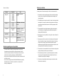
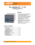
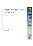
1
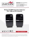
Black Link HD5
Wireless system of audio/video signal HD-SDI (HDMI)
transmission and data transmission (RS 485), dedicated for
professional HD-TV television
HDMI HD-SDI RS-485
869 MHz
9 V DC
÷
14 V DC
User’s manual
Warranty conditions
Declaration of conformity
OFDM SMA
ANTENNA
CONNECTOR
WARRANTY
24
MONTHS
Table of contents
Introduction . . . . . . . . . . . . . . . . . . . . . . . . . . . . . . . . . . . . . . . . . . . . . . . . . . . . . . . .
4
Set Contents . . . . . . . . . . . . . . . . . . . . . . . . . . . . . . . . . . . . . . . . . . . . . . . . . . . . . . . .
4
Specification . . . . . . . . . . . . . . . . . . . . . . . . . . . . . . . . . . . . . . . . . . . . . . . . . . . . . . . .
5
First launch setting . . . . . . . . . . . . . . . . . . . . . . . . . . . . . . . . . . . . . . . . . . . . . . . . .
6
. . . . . . . . 7
Connection diagrams for RS-485 connectors and power
System Installation . . . . . . . . . . . . . . . . . . . . . . . . . . . . . . . . . . . . . . . . . . . . . . . . .
7
Remarks regarding correct operation . . . . . . . . . . . . . . . . . . . . . . . . . . . . .
8
Warranty conditions
. . . . . . . . . . . . . . . . . . . . . . . . . . . . . . . . . . . . . . . . . . . . . . . 9
Utilization & Recycling . . . . . . . . . . . . . . . . . . . . . . . . . . . . . . . . . . . . . . . . . . . . . .
10
Declaration of conformity . . . . . . . . . . . . . . . . . . . . . . . . . . . . . . . . . . . . . . . . . .
11
Introduction
Black Link HD5 SET is an integrated system for video transmission in
high HD resolution (1080p,1080i,720p) and audio, dedicated for HD-TV
camera operator. System is characterized by lack of transmission delay
( < 1ms) and lack of image compression. Appliances are equipped with
wireless transmission system of RS-485 signal which enables remote
setting of camera parameters, communication with director etc.
Set contents:
Black Link HD5 set includes :
1. Black link HD5 transmitter with audio/video HD-SDI and HDMI input,
equipped with V-lock,
2. Black Link HD5 receiver with audio/video HD-SDI output,
3. 10 x AP05 Antennas,
4. 2 x 869 MHz Antennas,
5. 2 x Power Supply 12V/2,2 ADC with mini connectors x LR,
Antennas increasing operation range (intended for receiver)
6. 2 x SECTOR MIMO(V-V) 17dBi antenna,
7. 1 x SECTOR 17 dBi antenna.
Specification
Audio-video interface
RECEIVER
BLACK LINK HD5
HD-SDI / HDMI
HD-SDI
Power transmission
13 dBm
18 dBm
Frequencies
5,25 – 5,35, 5,47 – 5,725 (GHz) - DFS
Bandwidth
40 MHz
Transmission speed
Forward channel: 3 Gbps (400MBS)
Frequency modulation Forward channel: OFDM 16-QAM; Return Channel: OOK
Supported video resolution
720p @50/59.94/60 Hz, 1080i@50/59.94/60 Hz,
1080p @23,98/24/25/29,97/30 Hz
Supported audio formats
7.1/ 5.1/ Stereo (HD-SDI embedded)
Set range
≥ 30 m. LOS
(zexpandable coverage with additional antennas)
Transmission delay
≤ 1 ms
Image compression
brak
Antenna connectors
Data transmission
Supported data rates
Supported data formats
Power
Input current (maximum)
Operating temperature
Storage temperature
Dimensions [L × W × H]
Weight
4
TRANSMITTER
BLACK LINK HD5
5 × antenna VIDEO
5 × antenna VIDEO
SMA-RP 50Ω
SMA-RP 50Ω
1 × antenna DATA
1 × antenna DATA
869MHz SMA-RP 50Ω
869MHz SMA-RP 50Ω
interface: RS485
1200, 2400, 4800, 9600, 19200 [bps]
8n1, 8o1, 8e1
9-14 V DC
1,4A / 12V
1,2A / 12V
od 0°C do 55°C
od -20°C do 60°C
190 × 127 × 54mm
(with handles V-Lock: 190
190 × 127 × 54
× 127 × 90 mm)
0,8 kg (with handles
0,8 kg
V-Lock: 1,1 kg)
5
First launch setting
1. 1. Connect APO5 antennas to 1.....5 SMA connectors and 869 MHz
antenna to RS-485 antenna connector in transmitter.
2. 2. Connect APO5 antennas to 1.....5 SMA connectors and 869 MHz
antenna to RS-485 antenna connector in receiver.
ATTENTION: to extend operation range of the set (standard 30m)
additional antennas must be connected to receiver instead of the
APO05 aerial. Two Sector MIMO antennas must be connected to SMA
connectors: Antenna 1....2 and Antenna 3......4 . Sector 5 antenna must
be connected to SMA antenna 5 connector. In case of using external
antennas it is important to keep at least 2m distance between receiving
antennas (Sektor MIMO) and transmitting antenna (SEKTOR 5) should
be mounted the furthest possible from receiving antennas.
3. Connect audio/video HD-SDI and HDMI cables (transmitter must be
set to transmission of HDMI signals, see section „set -up of operation
parameters” page 7) from camera to receiver.
4. Connect audio/video HD-SDI cable from receiver to monitor/recorder/
mixer.
5. Connect RS-485 cables in transmitter and receiver (see section”
connection diagrams to RS-485 and power connectors”page7).
6. Fasten transmitter on camera and connect the power supply (from
battery or included DC power supply).
7. Connect the power supply to receiver from included DC power supply.
After turning it on PWR diode will flash, indicating that the device is
turned on. On the screen the state will be displayed:
-- podłączenia sygnału audio-wideo:
NO VIDEO - no audio/video signal,
VIDEO OK - correct connection of audio/video signal
-- connection between transmitter and receiver:
NO L INK - no wireless transmission,
L INK OK - correct wireless transmission.
6
When the screen on transmitter and receiver displays L INK OK
a VIDEO OK, t means correct transmission. Conventional data
transmission is running with speed 9600bps in 8n1 data format.
To change above parameters see section: „ COMISIONING - START UP”.
Connection diagrams for RS-485 connectors and
power
RS-485 CONNECTOR
PIN 1 - RS-485 A+
PIN 2 - RS-485 BPIN 3 - LINK IND.
PIN 4 - 5V DC
PIN 5 - GND
POWER CONNECTOR
PIN 1 - 9-14V DC
PIN 2 - N/C
PIN 3 - GND
System Installation
The RS-485 data transmission parameters (baud rate and data format)
and the AV input type (HD-SDI/HDMI) are set in the Tx module menu.
Open the device menu by pressing and holding the OK key for approx. 3
seconds. The top display line shows the current parameter name and the
bottom display line reads its settings.
Use the LEFT and RIGHT keys to navigate the menu.
Select the parameter settings by pressing the OK key. The arrow on the
screen right hand shows the current menu level.
Select the setting option and confirm by depressing the OK key for
approx. 3 seconds until you hear a beep.
Exit the menu to the main screen by depressing the EXIT key for approx.
3 seconds.
7
Warranty conditions
Menu is as follows:
Parametr
Ustawienia
Baud R.
1200
2400
4800
9600
19200
Data F.
8n1
8o1
8e1
V.Input
HD-SDI
HDMI
BUZZER
ON
OFF
Temp.
-
Opis
Baud Rate - data rates
RS-485
1. If the device is not be operating properly, make sure, before returning
the device for servicing, that everything was done according to the
operating manual.
Data Format - data formats
RS-485
2. If the faulty device is returned or send in for repairs, a thorough written
description of the signs of the device’s faulty operation, including the
operating environment and the manner in which they appear, should
be enclosed.
Video Input - select the
type of audio-video input
(transmitter only)
3. The prerequisite for exercising the warranty rights is enclosing the
proof of purchase, including the purchase date and description of
damage, with the faulty device.
Buzzerenable / disable sound
Temperature Information about the temperature inside the device
Remarks regarding correct operation
-- to ensure a stable, declared by the manufacturer reach the set,
the antenna must see each other, and the environment in which
the device operates, must be free of interference from other radio
transmissions operating at frequency set BLACK LINK HD5,
-- larger systems, composed of several sets should be set and executed
one after the other,
-- does not allow starting devices BLACK LINK 5HD without a properly
mounted antennas - threatens irreversible, not covered by the
warranty, damage the set.
8
Camsat grants a 24 month warranty for the Cam-9 transmission kit
4. Warranty repairs cover only faults occurring due to reasons inherent to
the sold device.
5. Warranty repairs will be carried out in the shortest possible amount of
time not exceeding 14 days, counting from the moment of accepting
the device for servicing. If parts need to be imported, the repair
deadline may be extended. After the repairs have been carried out, the
warranty period will be extended by the repair time.
6. The warrantor is not responsible for the loss of the device configuration
settings resulting from device repair or malfunction.
7. The warrantor may refuse to carry out warranty repairs or terminate
the warranty if it is determined that the seals placed on devices or
components comprising it are damaged.
8. All repair services resulting from the warranty are carried out at the
Camsat service exclusively.
9
The warranty does not cover
DECLARATION OF CONFORMITY
-- Mechanical damage of devices and failures occurring due to
fortuitous events, such as: fire, power grid overvoltage, electrical
discharges, power supply, effects of chemical substances.
-- Damage occurring due to: improper handling of the device, using the
device against its intended use or the operating manual, customer’s
negligence, improper use (temperature, humidity, flooding, dust,
sanding up, improper power supply voltage).
-- Claims on account of the technical parameters, if they are consistent
with those indicated by the manufacturer.
-- Marks created during usage, such as scratches, soiling and localised
wear are not covered by warranty.
In cases not regulated by the terms of this warranty sheet, the
appropriate provisions of the Civil Code are applicable
Utilization & Recycling
The mark presented to the left informs that this electrical or
electronic device, after its use has ended, cannot be thrown
together with household refuse. The device should be
delivered to a specialised collection point. Detailed
information about the closest collection point is available
from local authorities.
The proper disposal of this device allows for preserving
precious resources and avoiding the negative impact on health and
environment, which may be endangered if the waste is handled improperly.
Improper waste disposal is subject to penalties provided for in the
appropriate regulations.
I, the undersigned, representing the following company:
CAMSAT Przemysław Gralak
ul. Ogrodowa 2a 86-050 Solec Kujawski
hereby declare, with full responsibility, that the following device: CAM-9
is approved for operation within the EU and conforms to the fundamental
requirements and other relevant provisions of Directive 1999/5/WE:
Video
Fundamental requirements:
- Article of Directive 1999/5/WE
Applied standards
Assessment
Electromagnetic Compatibility – Art.3.1b
ETSI EN 301 489-1 V1.6.1
ETSI EN 301 489-3 V1.4.1
Conformity
Effective use of the frequency resources – Art.3.2
ETSI EN 300 440-1 V1.4.1
ETSI EN 300 440-2 V1.2.1
Conformity
Frequency range of the transmitter and receiver: 5725 MHz – 5875 MHz
Radiation power of the transmitter: ≤25,0 mW (14 dBm)
Dane
Wymagania zasadnicze:
- artykuł dyrektywy 1999/5/WE
Zastosowane normy
Ocena
Electromagnetic Compatibility – Art.3.1b
EN 301 489-1/-3
Conformity
Effective use of the frequency resources
– Art.3.2
EN 300 220-1/-2
Conformity
Safety requirements
- art. 3.1a
EN 60950-1+A11+A1+A12
EN 62311
Conformity
Frequency range of the transmitter and receiver: 869,40 MHz – 869,65 MHz
Transmitter power (measured): 169,8 mW (22,3 dBm)
Notified body participating in the
conformity assessment:
Responsible person:
Przemysław Gralak
EMCCert dr Rasek GmbH
Stoernhofer Berg 15
91364 Unterleinleiter,
Germany
Notified body number: 0678
Position:
właściciel
Signature:
Solec Kujawski 01.07.2014
10
Manufacturer:
CAMSAT Gralak Przemysław
Ul. Ogrodowa 2a
86-050 Solec Kujawski
Product offer and information: www.camsat.com
Service: [email protected]