1
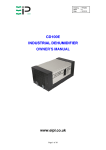
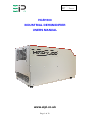
Drawing : - TPC413
Issue
:-1
Date
: - 22/01/14
HGR1500
INDUSTRIAL DEHUMIDIFIER
USERS MANUAL
www.eipl.co.uk
Page 1 of 12
Drawing : - TPC413
Issue
:-1
Date
: - 22/01/14
ORION
PACKAGE CONTENTS
Item
Description
Quantity
10272GR-US
Dehumidifier
1
3086144
Quick release hose coupling
1
3944110
PVC Tube – 3/8” I/D
7.8M
TPC413
Manual
1
Page 2 of 12
Drawing : - TPC413
Issue
:-1
Date
: - 22/01/14
UNPACKING
Thank you for deciding to purchase an Ebac dehumidifier. Like the many tens
of thousands of people who have already bought an Ebac dehumidifier we are
confident you will find it is the most effective answer to the problem of
condensation and dampness related problems
Carefully remove the HGR1500 dehumidifier unit from its transit box and
visually check for signs of transit damage. If there is evidence of damage DO
NOT attempt to operate the unit, call your supplier for advice. Do not discard
the packing; it will be useful when transporting the dehumidifier unit in the
future. Your dehumidifier is packed in a plastic wrapping, please ensure that it
is disposed of safely and where it will not be a danger to children.
INTRODUCTION
This user manual tells you how to use the HGR1500 dehumidifier. Please
read it thoroughly before operating the dehumidifier. If you have any questions
about the unit please contact our Customer Services Department at the
address shown at the back of the section or phone 01388 664400.
Dehumidifiers remove moisture from the air circulating through it.
Continuous operation reduces the relative humidity the air and this helps
prevent rust, rot, mould, mildew and condensation.
The HGR1500 dehumidifier consists of an air to air heat exchange, motor,
compressor unit, a refrigerant condenser and air circulating fan, a refrigerated
surface, a means for collecting and disposing of the condensed moisture and
a cabinet to house these components.
GENERAL
The HGR1500 dehumidifier must only be stored and transported in the
horizontal position. To operate, stand the unit on level ground, and connect
power supply and it is ready for operation.
When a generator is used to supply the power, it is essential to check the
minimum kva required in the technical section within this manual. The
generator must be started before connection is made to the dehumidifier.
Page 3 of 12
Drawing : - TPC413
Issue
:-1
Date
: - 22/01/14
OPERATION
The fan draws the moist air through the refrigerated surfaces which cools it
below its dew point, removing moisture which is collected and lead away. The
cool air then passes over the hot condenser, where it is repeated. With the
addition of other radiated heat the air is discharged into the room at a higher
temperature but a lower relative humidity than when it entered the unit.
Continuous circulation of the room air through the dehumidifier unit gradually
reduces the relative humidity in the room.
The HGR1500 dehumidifier is a robust, compact unit designed to control the
humidity in the enclosed space in which it is placed.
The unit is thermally protected and will switch off for a period if maximum
operating temperature of 40ºC is exceeded.
ELECTRICAL CONNECTIONS
WARNING THIS APPLIANCE MUST BE EARTHED
WIRING:
Connect the power mains cable/plug of the dehumidifier unit as follows:Brown
Blue
Green/Yellow
Live
Neutral
Earth (ground)
As the colour of the wires in the mains lead of this appliance may not
correspond with the coloured markings identifying the terminal in your own
plug, proceed as follows.
The wire which is coloured Green and Yellow must be connected to the
terminal marked E or by the Earth symbol or coloured Green or Green and
Yellow. The wire which is coloured Blue must be connected to the terminal in
the plug which is marked the letters N or coloured Black. The wire which is
coloured Brown must be connected to the terminal which is marked with the
letter L or coloured Red.
You must safely dispose of the non re-wireable plug once it has been
removed from the flexible cord. It is dangerous to attempt to insert the plug
into any electrical socket.
CHANGING THE FUSE
13 Amp fuses that are ASTA approved to BS1362 should only be used.
NON REWIREABLE PLUGS
The fuse cover must be refitted after the replacement of the fuse.
Page 4 of 12
Drawing : - TPC413
Issue
:-1
Date
: - 22/01/14
BASIC STEPS FOR DRYING
Ensure that all External doors and windows are closed. Where no doors or
windows are fitted, temporarily screen off the openings.
POSITIONING
For small areas position centrally in the area to be dried, for larger areas such
as open plan buildings, offices or factories, a number of dryers may be
required, in such cases they should be spaced evenly around the area.
Ensure that no unit is positioned in such a way that it blows directly into
another.
For private houses or flats, position the dryer on one floor at a time, starting at
the lowest floor, closing all internal doors on the floor previously dried.
Continue until all floor levels have been dried.
Note when a particular damp patch is to be dried out the air outlet grille should
be directed towards that area but should never be closer than 1m to the
surface. At no time should the inlet or outlet grilles be covered or obstructed.
DRAINAGE
Under most operating conditions water will be produced continuously and it is
important that it is drained away correctly and not allowed to spill. Any spillage
will evaporate and will therefore, have to be recycled through the dryer again,
which in effect, only prolongs the drying period.
PORTABLE CONTAINERS
Position a closed top container underneath the water discharge pipe
(approximately 25 litres capacity). Place a short length of pipe one end over
the discharge pipe and the other end in the container. Use a transparent
container, this will enable you to check the level of water and so prevent
overflowing. As the unit will be running for long periods of time, a regular
check should be made on the container water level.
PERMANENT DRAINAGE
Connect a flexible hose to the water drainage pipe of sufficient length so that
it will reach a permanent drain. The gravity head created will allow for a
gradual fall from the unit to the drain. Ensure that the hose is free of kinks and
is not allowed to rise at any point above the level of the discharge point from
the dehumidifier. Any air locks which may be created, should the level be
raised by the hose passing over obstructions, could cause the water to “back
up” the hose and spill from the drier.
Page 5 of 12
Drawing : - TPC413
Issue
:-1
Date
: - 22/01/14
SWITCHING ON
Plug the unit into the power supply and switch on. Set the illuminated Rocker
switch to the ON
SWITCHING OFF
Set the illuminated Rocker switch to the OFF position. Turn off the power
supply and disconnect.
Page 6 of 12
Drawing : - TPC413
Issue
:-1
Date
: - 22/01/14
SPECIAL FEATURES
DEFROST OPERATION
If the ambient temperature of the room in which the dehumidifier is
conditioning, falls below 15ºC ice will form on the evaporator coil as the air
passes over it. Over a period of time this build up of ice will effect the
efficiency of the dehumidifier on its ability to maintain the required set
conditions within the room.
The HGR1500 is therefore fitted with a defrost control device.
When the unit is operated in ambient of less than 15°C, a defrost cycle should
occur approximately every hour. The exact time is impossible to predict as the
unit is fitted with a temperature sensitive defrost control.
During the defrost cycle the high pressure hot gas from the compressor is
diverted into the evaporator coil where it melts the ice which has formed on
the evaporator coil.
Page 7 of 12
Drawing : - TPC413
Issue
:-1
Date
: - 22/01/14
SAFETY
• DO NOT Use the unit if the cabinet or power cord is damaged.
• DO NOT Insert objects into any of the grilles on the machine.
• DO NOT Cover or obstruct airflow from the grilles.
• DO NOT Operate the unit with the covers removed.
• DO NOT Attempt any repairs should the unit fail to operate.
• DO NOT Stand on the unit.
• DO NOT Attempt to lift heavy units unassisted.
• DO Check the plug on the equipment matches the supply.
• DO Use this unit for the purpose for which it was designed.
• DO Ensure the power cord and supply is earthed correctly.
• DO Check the voltage selection before attempting to power up the unit.
(Dual voltage units only)
• DO Use a Residual Current Device “RCD” where possible.
SERVICE
The machine should be serviced by qualified Ebac personnel or other persons
having technical competence in servicing refrigeration equipment following the
instructions in the Ebac service manual.
SPARES
Full spares parts listings and Ebac Service Manuals are available upon
request by contacting one of the Ebac Service Centres listed in this manual.
OZONE FRIENDLY
The gas which is inside the hermetically sealed refrigeration circuit is R22,
which is an HCFC. Under No circumstances should this gas be released into
the atmosphere. The unit should be serviced by trained personnel who will
reclaim the removed gas.
DISPOSAL OF UNIT
At the end of the machines working life the refrigerant must be disposed
of in the correct manner.
Page 8 of 12
Drawing : - TPC413
Issue
:-1
Date
: - 22/01/14
SPECIFICATIONS
10272GR-US
HEIGHT:
WIDTH:
DEPTH:
WEIGHT:
AIRFLOW:
VOLTAGE:
PHASE:
FREQUENCY:
MAXIMUM POWER:
MAXIMUM CURRENT:
GENERATOR SIZE:
FUSE RATING:
EFFECTIVE VOLUME:
REFRIGERANT TYPE:
REFRIGERANT
QUANTITY:
NORMAL
EXTRACTION:
21.5
21
35.6
165
295
115
1
60
900
8
1.5
13
300
R407c
0.585
105
Units Of
Measure
Inch
Inch
Inch
Lbs
CFM
V
Hz
W
A
Kva
A
m3
Kg
PPD
Noise Level: Less than 70dB (A) when running
Finish: Epoxy Coated Zintec Steel
Mobility: Light in construction and easily positioned.
Normal: Rated Extraction at 54ºF 70% RH Condition
"This product contains fluorinated greenhouse gases covered by the Kyoto Protocol. The
refrigeration system is hermetically sealed.
The Global Warming Potential (GWP) of refrigerants used in products manufactured by Ebac
Industrial Products Ltd is as follows
R134a – 1300
R407c – 1610
For type and weight of refrigerant contained in this unit, please refer to the product data label"
Page 9 of 12
Drawing : - TPC413
Issue
:-1
Date
: - 22/01/14
CONTACTING EBAC CUSTOMER SERVICES
If you have nay further queries please contact the Ebac Customer
Services Department on 01388 664400 and have the following information
at hand:• Part Number and Serial Number of the machine (located on the rating plate
and the front of the machine).
• Full name and address.
• Where your machine was purchase.
Page 10 of 12
Drawing : - TPC413
Issue
:-1
Date
: - 22/01/14
LIMITED WARRANTY
Our products carry a one-year unconditional warranty against any defects in
workmanship or material. This warranty will cover all parts and labour
required to repair your Ebac product. This warranty is invalid if the unit has
been abused, damaged, whether intentional or accidental, or if any
modifications have been made to the unit.
THE FOREGOING WARRANTY IS EXCLUSIVE AND IS ISSUED IN LIEU OF
ALL OTHER WARRANTIES (WHETHER WRITTEN, ORAL, OR IMPLIED)
INCLUDING THE WARRANTY OF MERCHANTABILITY AND THE
WARRANTY OF FITNESS FOR A PARTICULAR PURPOSE.
EBAC
INDUSTRIAL PRODUCTS, INC. DISCLAIMS ANY LIABILITY FOR
CONSEQUENTIAL DAMAGES, LOST PROFITS, OR INCIDENTAL
DAMAGES FOR BREACH OF ANY WRITTEN OR IMPLIED WARRANTY
WITH RESPECT TO THE FOREGOING DESCRIBED MERCHANDISE.
For Your Records: Model:____________________
S/N:______________________
Date Received:______________
SAVE THIS SECTION FOR YOUR RECORDS
CLIP AND RETURN THIS CARD
PLEASE NOTE
To ensure that your
Ebac Dehumidifier is
accorded
the
full
coverage provided by
this warranty, please
complete and mail this
card at your earliest
convenience.
Thank You
WARRANTY REGISTRATION
DATE
MODEL ___________ S/N ________________ RECEIVED ________________
OWNER __________________________________________________________
ADDRESS ________________________________________________________
CITY __________________________ STATE ________ ZIP _______________
COMMENTS ______________________________________________________
_________________________________________________________________
Ebac Industrial Products.
700 Thimble Shoals Boulevard, Suite 109, Newport News, Virginia. 23606-2575
Page 11 of 12
Drawing : - TPC413
Issue
:-1
Date
: - 22/01/14
UK Head Office
American Sales Office
German Sales Office
Ebac Industrial Products Ltd
St Helens Trading Estate
Bishop Auckland
County Durham
DL14 9AD
Ebac Industrial Products Inc
700 Thimble Shoals Blvd.
Suite 109, Newport News
Virginia, 23606-2575
USA
Ebac Industrial Products Ltd.
Gartenfelder Str. 29-37
Gebäude 35
D-13599, Berlin
Germany
Tel: +44 (0) 1388 664400
Fax: +44 (0) 1388 662590
Tel: +01 757 873 6800
Fax: +01 757 873 3632
Tel: +49 3043 557241
Fax: +49 3043 557240
www.eipl.co.uk
[email protected]
www.ebacusa.com
[email protected]
www.eip-ltd.de
[email protected]
Page 12 of 12