1
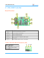
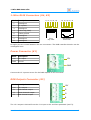
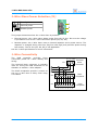
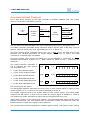
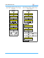
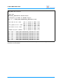
1-Wire RGB Controller
User Manual
February 2015
1-Wire RGB Controller
Table of Contents
1
Features
3
2
Technical Specifications
3
3
Warnings
3
4
1-Wire RGB Controller
Board Overview
1-Wire Terminal Block Connector (K3)
1-Wire RJ45 Connectors (K4, K5)
Power Connector (K1)
RGB Outputs Connector (K2)
1-Wire Slave Power Selection (J1)
1-Wire Connectivity
Communications Protocol
4
4
4
5
5
5
6
6
7
5
Software Support
1-Wire Automation Server
ows
owfs
10
10
10
10
6
Legal Information
Disclaimer
Trademarks
12
12
12
7
Contact Information
12
Revision History
Date
Authors
Description
2013-03-06 Peter S'heeren
Initial release.
2013-04-28 Peter S'heeren
Added section about software support.
Second release.
2013-07-21 Peter S'heeren
Added section about owfs software support.
Third release.
2015-02-17 Peter S'heeren
Added section about 1-Wire Automation Server
software support.
Fourth release.
2
User Manual
1-Wire RGB Controller
1 Features
▪
Three individually controllable PWM
output channels able to directly drive a
12V LED RGB strip.
▪
Approx. 1000 Hz PWM cycle frequency.
▪
PWM duty cycle adjustable from 0 % to
99.61 %.
▪
PWM duty cycle changes are free of
glitches avoiding visual flickering.
▪
PWM signals are shifted 120 degrees
for optimal power distribution.
▪
Separate circuits for 1-Wire and 12 V RGB.
▪
A fuse protects the 12 V RGB circuit.
▪
Three connection points for 1-Wire cabling and wiring.
▪
Drives RGB LED strips up to 4 A per channel (for a max. total of 144 W).
2 Technical Specifications
Weight
45 g (with fuse)
Dimensions
92 mm x 55 mm x 25 mm (W x D x H)
3 Warnings
WARNINGS!
▪ Beware the polarity of the power connector, do not inverse.
▪ This device is not suitable for driving 24 V LED strips.
User Manual
3
1-Wire RGB Controller
4 1-Wire RGB Controller
Board Overview
1
2
3
5
4
6
7
Mark
Label
Description
1
K3
1-Wire bus terminal block connector
2
F3
Fuse 10 A (max 12 A allowed)
3
K5
1-Wire bus RJ45 connector
4
K4
1-Wire bus RJ45 connector
5
K1
Power connector to supply the RGB outputs
6
K2
RGB outputs
7
J1
Power supply selection for the 1-Wire slave
1-Wire Terminal Block Connector (K3)
Mark
5V
5 V supply
1W
1-Wire DQ line (data)
GND
4
Description
5V
1W GND
Ground
User Manual
1-Wire RGB Controller
1-Wire RJ45 Connectors (K4, K5)
Mark
Description
1
Unassigned
2
+5 V power
3
Unassigned
4
1-Wire DQ (data)
5
1-Wire ground
6
Unassigned
7
Unassigned
8
Unassigned
1 2 3 4 5 6 7 8
1 2 3 4 5 6 7 8
Plug
top view
Receptacle
front view
All eight pins are routed between the two connectors. The RGB controller doesn't use the
unassigned lines.
Power Connector (K1)
Mark
Description
12V
12 V input
GND
Ground
12V
GND
Connect the 12 V power source for the RGB outputs to this connector.
RGB Outputs Connector (K2)
Mark
Description
12V
12 V output
R
Red channel output
G
Green channel output
B
Blue channel output
12V
R
G
B
The 12 V output is derived from the 12 V input on K1 and fuse-protected (see F3).
User Manual
5
1-Wire RGB Controller
1-Wire Slave Power Selection (J1)
1 2 3 Description
3
External power
2
Parasite power
1
This jumper determines how the 1-Wire slave is powered:
▪
External power: the 1-Wire slave draws power from the 5V line. Be sure the voltage
is provided to one of the 1-Wire connection points (K3, K4, K5).
▪
Parasite power: the 1-Wire slave uses an internal capacitor as its power source. The
capacitor is charged during idle time (DQ line held high) and provides power during
bus activity. The 5V line (K3, K4, K5) is not applicable.
See the 1-Wire specification for more information.
1-Wire Connectivity
The
RGB
controller
provides
three
connection points for 1-Wire cabling and
wiring.
5V 1W GND
The terminal block connector is typically
used for wiring the RGB Controller to an
AbioWire or another 1-Wire adapter.
The RJ45 receptacles provide a means to
set up a 1-Wire bus in daisy chain using
UTP cables.
K4
RJ45
receptacle
K5
RJ45
receptacle
1
6
Terminal
block
connector
K3
2
3
4
5
6
7
8
User Manual
1-Wire RGB Controller
Communications Protocol
The 1-Wire slave function on the RGB controller is a Maxim DS2408 chip. The 1-Wire
slave is connected to the PWM controller.
1-Wire
DQ
RED PWM
PIO[7..0]
DS2408
1-Wire
slave
GREEN PWM
PWM
controller
STRB
BLUE PWM
See the Maxim DS2408 datasheet for more information about the 1-Wire slave chip.
The PWM controller generates three individual output signals with a 256-step cycle at
approx. 1000 Hz and a duty cycle adjustable from 0 % to 99.61 %.
The host system sends command bytes over the 1-Wire bus to the PIO lines of the
DS2408. The DS2408 generates an output strobe (STRB line) to inform the PWM
controller a command byte is available.
The host system must ensure the RSTZ pin on the DS2408 is configured as STRB.
DS2408 control/status register bit 2 – ROS: RSTZ Pin Mode Control – configures the
RSTZ pin.
The PWM controller maintains a
set of registers the host system
can write data into:
▪
R_EN: Red channel enable.
▪
G_EN: Green channel enable.
▪
B_EN: Blue channel enable.
▪
R_ON: Red PWM ON period.
▪
G_ON: Green PWM ON period.
▪
B_ON: Blue PWM ON period.
7
R_EN
0
R_ON
0
0
0
0
0
0
0
0
7
G_EN
0
G_ON
0
0
0
0
0
0
0
0
7
B_EN
0
B_ON
0
0
0
0
0
0
0
0
0
0
0
The reset values are shown.
The ON period registers determine the duty cycle of each output signal. A value of zero
means 0/256 or 0 %, a value of 255 means 255/256 or 99.61 %.
The enable registers control the enable state of each output signal. The enable state
overrule the ON period. A value of zero means the output signal is disabled, a value of
one means the output generates a signal with the programmed duty cycle.
When data is written to the ON period registers, the generated PWM output signals won't
change immediately. The host system has to send the commit command to order the
PWM controller to make the register values effective.
The commit command also embeds the enable register values. This means, unlike writing
User Manual
7
1-Wire RGB Controller
data to an ON period register, writing data to the enable registers immediately takes
effect.
Command Byte
7
0
6
5
4
Function
3
2
1
0
R_ON[7..4]
0
0
0
0
Set red ON period high nibble
R_ON[3..0]
0
0
0
1
Set red ON period low nibble
G_ON[7..4]
0
0
1
0
Set green ON period high nibble
G_ON[3..0]
0
0
1
1
Set green ON period low nibble
B_ON[7..4]
0
1
0
0
Set blue ON period high nibble
B_ON[3..0]
0
1
0
1
Set blue ON period low nibble
B_EN G_EN R_EN
0
1
1
0
Set RGB enable flags and commit
The family code of the DS2408 is 29h. Since the family code alone doesn't uniquely
identify a 1-Wire RGB Controller device, the host system must associate the full 8-byte
ROM code with the device.
The host system is expected to use Standard speed when communicating with the RGB
controller over the 1-Wire bus.
The host system needs to execute the following 1-Wire command sequence in order to
configure the RSTZ pin on the DS2408 as STRB.
start
1-Wire Reset
1-Wire Write Byte
55h (match ROM)
1-Wire Write Bytes
29h xxh xxh xxh
xxh xxh xxh xxh
1-Wire Write Bytes
CCh 8Dh 00h 04h
stop
8
User Manual
1-Wire RGB Controller
The following diagram shows how to
write byte value 46h to the RGB
controller.
The following diagram shows how to
write a string of byte values to the
RGB controller.
start
start
1-Wire Reset
1-Wire Reset
1-Wire Write Byte
1-Wire Write Byte
55h (match ROM)
55h (match ROM)
1-Wire Write Bytes
1-Wire Write Bytes
29h xxh xxh xxh
xxh xxh xxh xxh
29h xxh xxh xxh
xxh xxh xxh xxh
1-Wire Write Bytes
5Ah 46h B9h
1-Wire Write Bytes
5Ah value value
1-Wire Read Byte
result
1-Wire Read Byte
result
result equals AAh?
Y
stop
N
error
result equals AAh?
Y
data bytes left?
N
N
error
stop
Y
1-Wire Read Byte
pio
User Manual
9
1-Wire RGB Controller
5 Software Support
1-Wire Automation Server
Before the RGB channels can be programmed, the RSTZ pin of the DS2408 must be
configured as STRB output. For example:
dev "29-11CEE1" pio rstz strobe
Use client command Device RGB Controller to control the RGB channels. Examples:
dev "29-11CEE1" rgbctrl red=100
Turn on the red channel at 100/256 = 39 %.
dev "29-11CEE1" rgbctrl red=64 green=128 blue=192
Turn on the RGB channels: red at 25 %, green at 50 %, blue at 75 %.
You can set channel values in advance and turn on and off channels later. For example:
dev "29-11CEE1" rgbctrl red=off,200 green=off,200 blue=off,200
dev "29-11CEE1" rgbctrl red=on
dev "29-11CEE1" rgbctrl green=on blue=on red=off
The following command sets all channels to zero and turns them off.
dev "29-11CEE1" rgbctrl clear
ows
Software package ows v1.0.0 and later includes program owrgctrl. This program
enables you to fully control the 1-Wire RGB Controller.
Example invocations of the program:
> owrgbctrl.exe -lu -id 29-11CEE1 -c
This command clears all internal registers of the target 1-Wire RGB controller.
> owrgbctrl.exe -lu -id 29-11CEE1 -ro 20 -go 50 -bo 80
This command sets the internal RGB registers of the target 1-Wire RGB controller to
(20;50;80).
Specify -v to see the actual command bytes that are written to the RGB controller.
owfs
It's assumed you're using the filesystem client of the owfs package. In the examples it's
suppose you've specified /mnt/onewire/ as the mount directory for the 1-Wire file
system.
Since owfs inverts all accesses to PIO channels, the default positive logic becomes
negative logic and one has to invert all command values before sending them out.
10
User Manual
1-Wire RGB Controller
# Mount point for owfs
OWFS_MNT=/mnt/onewire
# ROM code
OWRGBCTRL_ROMCODE=29.E1CE11000000
# Configure pin RSTZ as STROBE output
echo "1" > $OWFS_MNT/$OWRGBCTRL_ROMCODE/strobe
# Set red to 20 = 14h:
10h -> invert => EFh = 239
#
41h -> invert => BEh = 190
# Set green to 50 = 32h: 32h -> invert => CDh = 205
#
23h -> invert => DCh = 220
# Set blue to 80 = 50h: 54h -> invert => ABh = 171
#
05h -> invert => FAh = 250
# Enable R,G,B & commit: 76h -> invert => 89h = 137
#
echo "239" > $OWFS_MNT/$OWRGBCTRL_ROMCODE/PIO.BYTE
echo "190" > $OWFS_MNT/$OWRGBCTRL_ROMCODE/PIO.BYTE
echo "205" > $OWFS_MNT/$OWRGBCTRL_ROMCODE/PIO.BYTE
echo "220" > $OWFS_MNT/$OWRGBCTRL_ROMCODE/PIO.BYTE
echo "171" > $OWFS_MNT/$OWRGBCTRL_ROMCODE/PIO.BYTE
echo "250" > $OWFS_MNT/$OWRGBCTRL_ROMCODE/PIO.BYTE
echo "137" > $OWFS_MNT/$OWRGBCTRL_ROMCODE/PIO.BYTE
This shell script excerpt sets the internal RGB registers of the target 1-Wire RGB
controller to (20;50;80).
User Manual
11
1-Wire RGB Controller
6 Legal Information
Disclaimer
Axiris products are not designed, authorized or warranted to be suitable for use in space,
nautical, space, military, medical, life-critical or safety-critical devices or equipment.
Axiris products are not designed, authorized or warranted to be suitable for use in
applications where failure or malfunction of an Axiris product can result in personal
injury, death, property damage or environmental damage.
Axiris accepts no liability for inclusion or use of Axiris products in such applications and
such inclusion or use is at the customer's own risk. Should the customer use Axiris
products for such application, the customer shall indemnify and hold Axiris harmless
against all claims and damages.
Trademarks
All product names, brands, and trademarks mentioned in this document are the property
of their respective owners.
7 Contact Information
Official website: http://www.axiris.eu/
12
User Manual