1
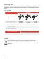
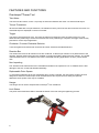
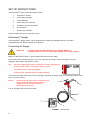
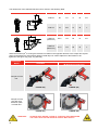
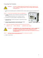
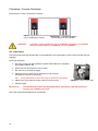
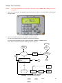
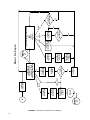
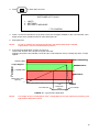
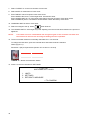
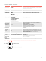
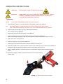
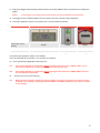
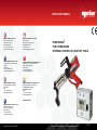
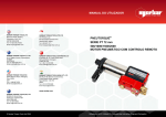
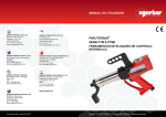
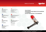
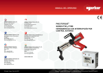
OPERATOR’S MANUAL NORBAR TORQUE TOOLS LTD Beaumont Road, Banbury, Oxfordshire, OX16 1XJ UNITED KINGDOM Tel + 44 (0)1295 270333 Email [email protected] NORBAR TORQUE TOOLS PTE LTD 194 Pandan Loop #07-20 Pantech Business Hub SINGAPORE 128383 Tel + 65 6841 1371 Email [email protected] NORBAR TORQUE TOOLS PTY LTD 45–47 Raglan Avenue, Edwardstown, SA 5039 AUSTRALIA Tel + 61 (0)8 8292 9777 Email [email protected] NORBAR TORQUE TOOLS (SHANGHAI) LTD E Building–5F, no. 1618 Yishan Road, Minhang District, Shanghai CHINA 201103 Tel + 86 21 6145 0368 Email [email protected] NORBAR TORQUE TOOLS INC 36400 Biltmore Place, Willoughby, Ohio, 44094 USA Tel + 1 866 667 2279 Email [email protected] NORBAR TORQUE TOOLS INDIA PVT. LTD Plot No A-168, Khairne Industrial Area, Thane Belapur Road, Mahape, Navi Mumbai – 400 709 INDIA Tel + 91 22 2778 8480 Email [email protected] PNEUTORQUE® PTM & PTME SERIES EXTERNAL CONTROL (EC) SHUT-OFF TOOLS www.norbar.com NORBAR TORQUE TOOLS (NZ) LTD B3/269A Mt Smart Road Onehunga, Auckland 1061 NEW ZEALAND Tel + 64 9579 8653 Email [email protected] © Norbar Torque Tools Ltd 2007 Part Number 34323 | Issue 3 | Original Instructions (English) CONTENTS Part Numbers Covered By This Handbook 2 Safety 3 Introduction Parts Included Accessories 4 4 5 Features And Functions ® Pneutorque Power Tool Tool Controller 6 6 7 Set Up Instructions ® Pneutorque Hanger Connecting Air Supply Torque Reaction Connecting Tool Controller Clockwise / Counter-Clockwise Air Lubrication Norbar Tool Controller 8 8 8 9 11 12 12 13 Operating Instructions Tightening Releasing 18 18 20 Maintenance Air Lubrication Gearbox Silencer Drive Square Printer Paper Replacement Transducer Calibration Cleaning Disposal 21 21 21 21 22 22 22 22 22 Specifications Power Tool Only Tool Controller Only Power Tool & Tool Controller 23 23 24 25 Declaration Of Conformity 26 Trouble Shooting 27 Glossary Of Terms 27 Appendix A – Use With a Non-Norbar Controller General Specifications Electromagnetic Compatability (EMC) Transducer Excitation Considerations 28 28 28 28 Appendix B – Using The Tool Controller keypad 29 1 PART NUMBERS COVERED BY THIS HANDBOOK ® This handbook covers the setup and use of the Norbar Pneutorque PTM & PTME Series External Control ® (EC) shut-off tools; this incorporates the Norbar Pneutorque External Control power tool and a Norbar Tool Controller. ® The use of the Pneutorque with a non-Norbar Tool Controller is covered in Appendix A. Pneutorque® Power Tool Part Number 18120.B06 18121.B06 18122.B06 18123.B08 18124.B08 18144.B06 18145.B08 NOTE: Model PTM-52-500-B-EC PTM-52-800-B-EC PTM-72-1000-B-EC PTM-72-1350-B-EC PTM-72-2000-B-EC PTME-72-1000-B-EC PTME-72-2000-B-EC Tool Capacity 500 N·m 800 N·m 1000 N·m 1350 N·m 2000 N·m 1000 N·m 2000 N·m The main PTM & PTME models are listed above. Other PTM & PTME external control tools with minor variances are also covered. Description of options: Part Number Option *****.B** *****.*06 *****.*08 Description Bi-directional (Clockwise and Counter-Clockwise). 3/4” A/F drive square size. 1” A/F drive square size. Model Option PTM -**-****-*-EC PTME -**-****-*-EC PTM*-52-****-*-EC PTM*-72-****-*-EC PTM*-**-1000-*-EC PTM*-**-****-B-EC Description ® Pneutorque Twin Motor. ® Pneutorque Twin Motor fixed nose extension. 52mm diameter gearbox. 72mm diameter gearbox. Maximum torque in N·m. Bi-directional (Clockwise and Counter-Clockwise). Tool Controllers Part Number 60244 60254 NOTE: 2 Description Tool Controller for EC tool. Tool Controller for EC tool with built-in printer. The main tool controller models are listed above. Other tool controller models with minor variances are also covered. SAFETY IMPORTANT: DO NOT OPERATE THE TOOL BEFORE READING THESE INSTRUCTIONS. FAILURE TO DO SO MAY RESULT IN PERSONAL INJURY OR DAMAGE TO THE TOOL. This tool is intended for use with threaded fasteners. The use of ear protectors is recommended. Do not use these tools in potentially explosive atmosphere as they contain grease, which may cause an explosion hazard in the presence of pure oxygen. These tools also contain aluminium alloy components which may cause a hazard in certain explosive environments. Unexpected tool movement due to reaction forces or breakage of drive square or reaction bar may cause injuries. Isolate the tool from all energy sources before changing or adjusting the drive square or socket. There is a risk of crushing between the reaction bar and work piece. Keep hands away from reaction bar. Keep hands away from tool output. Keep loose clothing, hair, etc. from being caught in any rotating part of the tool. These tools require a reaction bar. See section on Torque Reaction. Ensure all hoses are correctly fitted before switching on the air supply. This avoids the risk of injury by whipping air hoses. Unexpected direction of drive square movement can cause a hazardous situation. Use only sockets and adaptors which are in good condition and are intended for use with power tools. ® Pneutorque Wrenches are non-impacting, torque controlled threaded fastener tightening tools and must always be operated with the following: Clean dry air supply with a minimum flow of 19 litres/sec (40 CFM). Lubro Control Unit or similar Filter, Regulator and Lubricator Unit 1/2” Bore (12 mm). Impact or high quality sockets. Reaction bar. 3 INTRODUCTION ® The Pneutorque PTM & PTME External Control (EC) series tools are air driven power tools designed for applying torque to threaded fasteners. The Tool Controller is used to accurately control the shut-off torque of ® the Pneutorque and display the torque applied. There are models to cover torque capacities of 500 N·m to 2000 N·m. Parts Included Description Part Number PTM-72 PTM-52 PTME-72 Visual difference ® Pneutorque power tool Cranked reaction bar (fitted) Reaction bar retaining circlip (fitted) Hanger (fitted) Calibration certificate Operators handbook (with language CD [if required]) The Tool Controller Includes Tool controller Tool Head Lead (6m) Mains Lead 18646 26588 18747 - 18122.B6 18123.B8 18124.B8 18494 26486 18747 - 34323 34323 18120.B06 18121.B06 18144.B6 18145.B8 18747 34323 Part Number No Printer 60244 61127.600 Various With Printer 60254 61127.600 Various Disposal This symbol indicates that the product must not be disposed of in the general waste. Please dispose of according to your local recycling laws and regulations. Contact your distributor or see the Norbar web site (www.norbar.com) for further recycling information. 4 Accessories For The Pneutorque ® PTM-52 Part Number PTM-72 PTME-72 Air Coupling Socket for Hose 28933 28933 28933 Lubro Control Unit 3/4” Drive Square (fixing screw) 1” Drive Square (fixing screw) 3/4” Drive Shaft (fixing pin) 1” Drive Shaft (fixing pin) Reaction Plate [NOTE 1] 16074 18544 (25351.30) 18545 (25351.30) - 16074 18779 (25352.45) 18492 (25352.45) - 16074 77112.2 (26287) 18802 (26287) 18298 18298 18558 18290 18576 18292 18590 18293 18591 (3/4”) 18594.006 (3/4”) 18594.009 (3/4”) 18594.012 18591 (1”) 18755.006 (1”) 18755.009 (1”) 18755.012 (3/4") 19087.009 (1") 19089.009 (3/4") 19087.012 (1") 19089.012 - Reaction Adaptor [NOTE 1] - Single-sided Reaction Plate - Double-sided Reaction Plate Silencer 6” Blade Nose Extension 9” Blade Nose Extension 12” Blade Nose Extension 9” Nose Extension for Truck & Bus Wheels 12” Nose Extension for Truck & Bus Wheels NOTE 1: 18591 - Requires both ‘Reaction Plate’ and ‘Reaction Adaptor’ to be used together. For The Tool Controller Printer Paper Rolls (Purchased from www.rs-components.com) Part Number No Printer With Printer 224-9853 5 FEATURES AND FUNCTIONS Pneutorque® Power Tool Twin Motor The tools use two motors; motor 1 to quickly run-down the fastener and motor 2 to achieve final torque. Torque Transducer All tools are fitted with a torque transducer, the transducer forms part of the tool and cannot be removed. The measured torque is displayed on the tool controller. Trigger The trigger controls the flow of air. The more the trigger is pressed the more air flows into the tool. This allows for slow positioning of socket and reaction bar. Once positioning is complete, the trigger must be fully pressed for correct torque application. Clockwise / Counter-Clockwise Selector Tools can tighten and release both clockwise & counter-clockwise threaded fasteners. Reaction Bar The reaction bar ensures all reaction forces are contained, so that torque reaction is not passed back to the operator. Several reaction bar types are available, including the PTME / Nose Extension reaction. The PTME / Nose Extension are for use where tool access is restricted including applications on heavy vehicle wheel nuts. Non-Impacting Low vibration levels make these tools comfortable and safe for the operator to use. In addition there is less damage to the tool, socket and threaded assembly. Replaceable Drive Square To avoid internal damage to the tool (especially due to torque overload), the output drive square has been ® designed to shear first. Pneutorque tools are fitted with a drive square that can easily be replaced; alternative drive square sizes may be available. Hanger ® The hanger can be used to suspend the Pneutorque from a balancer. Limit Status The power tool is fitted with LEDs to indicate the status of the tool during the tightening process. 6 Tool Controller Display The backlit display shows an accurate reading of the torque applied and the settings for the tool controller. Torque Limits The Tool Controller has 12 sets of limits to control the power tool shut-off. Each limit has a target value and upper and lower allowances. When the lower allowance is reached the power tool to shut-off. Limit Status The limit status is shown as LO/OK/HI on the display and with bright LED’s to show ‘PASS’ or ‘FAIL’. Serial Port A serial port is provided for data output to a computer or printer. Options include sending limit status, time and date. Printer The 60254 version of the controller has a built-in printer which allows printing of the torque data. 7 SET UP INSTRUCTIONS ® The Pneutorque set up covers the following items: ® 1. Pneutorque Hanger 2. Connecting Air Supply 3. Torque Reaction 4. Connecting Tool Controller 5. Clockwise / Counter-Clockwise 6. Air Lubrication 7. Norbar Tool Controller Please complete the set up in the order shown. Pneutorque® Hanger ® The Pneutorque hanger (Figure 1-E) is designed to be used with a suitable balancer to provided comfortable tool use. Remove hanger if not required. Connecting Air Supply WARNING: TO AVOID HAZARD FROM WHIPPING AIR HOSES MAKE ALL CONNECTIONS TO THE TOOL BEFORE TURNING ON THE AIR SUPPLY. Make sure all hoses are clean, in good condition and free from dirt / water. Connect the tool air inlet hose (Figure 1-C) to the outlet side of the lubro control unit (Figure 1-B) (not supplied), observing air flow direction arrows. TIP: On tools supplied with quick air couplings, fit the coupling plug to the tool inlet and the coupling socket to air hose. To connect, push couplings together. To disconnect, pull back lock on socket coupling. Connect the inlet side of the lubro control unit (Figure 1-B) to the air supply (Figure 1-A) using a minimum hose size of 1/2” bore (12mm). NOTE: Avoid using 1/2” bore hoses of longer than 5 meters from the supply to the pressure regulator unit as this will reduce the performance of the tool. E D C Turn on air supply and check for air leaks. F G A B FIGURE 1 - Connections 8 Torque Reaction The reaction bar ensures all reaction forces are contained, so torque reaction is not passed back to the operator. Several reaction bar types are available. Fit reaction bar as detailed below: Tool Model Reaction Bar Type Cranked reaction bar (standard) Single sided reaction plate (option) Double sided reaction plate (option) Fitting Instructions Fit reaction bar / plate (Figure 1-D) over the drive square to engage reaction splines. Secure with circlip supplied. Fit as instructions supplied with nose extension. PTM Nose Extension (option) PTME Nose Extension (Standard) Factory fitted, not removable. It is essential the reaction bar rests squarely against a solid object or surface adjacent to the fastener to be tightened. The contact area must be within the shaded area of figure 2, with the contact area as large as possible. Extra Length Socket Standard Length Socket Torque Reaction should be taken in the shaded areas only FIGURE 2 – Safe reaction window WARNING: CARE MUST BE TAKEN TO ENSURE THAT THE REACTION BAR IS ONLY USED WITHIN THE LIMITATIONS SHOWN IN FIGURE 2. For special applications or where extra deep sockets must be used the standard bar may be extended but only within the limitations shown on Figure 2. Alternative reaction bars are available, see page 5. WARNING: FAILURE TO OBSERVE THE LIMITATIONS SHOWN IN FIGURE 2 WHEN MODIFYING STANDARD REACTION BARS MAY RESULT IN PREMATURE WEAR OR DAMAGE TO THE TOOL. Standard drive square extensions MUST NOT be used as these will cause serious damage to the tool output drive. A range of nose extensions is available for applications where access is restricted. These are designed to support the final drive correctly. 9 The dimensions of the standard reaction bars is shown in the following table: Reaction Bars (Standard) Reaction Bars (PTME) Tool ‘L’ ‘A’ ‘B’ ‘W’ ‘SQ’ PTM-52 60 131 71 35 3/4” PTM-72 75 165 91 48 1” Tool ‘L’ ‘A’ ‘B’ ‘W’ ‘SQ’ PTME-72 (1000 N·m) 80.5 110 63 12 3/4” PTME-72 (2000 N·m) 51.5 110 62 16 1” ® When the Pneutorque is running the reaction bar rotates in the opposite direction to the output drive square and must be allowed to rest squarely against a solid object or surface adjacent to the fastener to be tightened. See figure 3(a), 3(b), 3(c) and 3(d). Pneutorque Model Torque Reaction ® Clockwise Counter-Clockwise (Bi Directional Tools Only) FIGURE 3(a) FIGURE 3(b) FIGURE 3(c) FIGURE 3(d) Example of PTM tool. Example of PTM tool with nose extension option or PTME tool. WARNING: 10 ALWAYS KEEP HANDS CLEAR OF THE REACTION BAR WHEN THE TOOL IS IN USE OR SERIOUS INJURY MAY RESULT. Connecting Tool Controller WARNING: THE TOOL CONTROLLER IS SUPPLIED WITH 2 KEYS TO UNLOCK THE DOOR. THESE KEYS ARE REQUIRED FOR AUTHORISED MAINTENANCE PURPOSES ONLY. 1. Attach the tool head lead (Figure 1-G) between the tool connector (Figure1-F) and Tool Controller (Figure 4). NOTE: For use with a non-Norbar controller see Appendix A. 2. If using the serial port, connect computer or serial printer to ‘RS232’ connector. (For model 60254 with printer there is no RS232 connector). 3. The ‘Solenoid’ connector (if fitted) is not applicable to this tool. 4. If using socket tray, connect to ‘Socket Tray’ connector (for custom applications only). 5. Connect mains power lead from Tool Controller mains supply. A supply of between 100 VAC– 240 VAC is required. TIP: If the mains plug needs changing connect the new plug as follows: BROWN – LIVE WARNING: NOTE: FIGURE 4 – Norbar Tool Controller BLUE – NEUTRAL GREEN/YELLOW - EARTH IT IS IMPORTANT THAT LIVE NEUTRAL AND EARTH ARE ALL CONNECTED BETWEEN THE CONTROL BOX AND MAINS SUPPLY. IF NO EARTH IS AVAILABLE (2 WIRE MAINS SUPPLY) IT IS RECOMMENDED THAT A SEPARATE EARTH BE CONNECTED BETWEEN THE CONTROL BOX AND A SUITABLE EARTH. If the tool controller plug is fitted with a fuse, a 5 amp value is required. If in doubt consult a qualified electrician. 6. Switch on mains power. 11 Clockwise / Counter-Clockwise Set clockwise / counter-clockwise as required. FIGURE 5(a) – Clockwise (Arrow towards drive square) WARNING: FIGURE 5(b) – Counter-Clockwise (Arrow away from drive square) FAILURE TO FULLY ENGAGE THE CLOCKWISE / COUNTER- CLOCKWISE SELECTOR WILL RESULT IN DAMAGE TO THE GEARBOX. Air Lubrication The tool must be used with oil lubrication in the supplied air, this is achieved by using a Lubro Control Unit (not supplied). Set the air lubrication: a. Fill Lubro Control Unit with hydraulic oil (Shell Tellus S2M 32 or equivalent good quality hydraulic oil). b. Ensure the tool drive square is free to rotate. c. Run the tool by pressing the trigger. d. Adjust the Lubro Control Unit for maximum tool air pressure. Air pressure is shown on the gauge. TIP: Using maximum air pressure will give maximum tool speed. e. Adjust Lubro Control Unit to supply 6 drops of oil per minute. f. Release trigger. IMPORTANT: THE WRENCH MUST BE FREE RUNNING WHILE ADJUSTING THE AIR PRESSURE TO GIVE THE CORRECT SETTING. See Lubro Control Unit handbook for more details. 12 FIGURE 6 – Lubro Control Unit Norbar Tool Controller NOTE: ® The torque applied by the Pneutorque depends on the LOWER LIMIT setting on the Tool Controller. 1. Switch on Tool Controller. The display & keypad are shown in Figure 7, for further details on the keypad see Appendix B. FIGURE 7 – Display & Keypad 2. The tool controller will follow the flow diagram shown in Figure 8. For “Smart” transducers the tool controller will proceed to “Measure”. For “Non-Smart” transducer the tool controller will show “CONNECT TRANSDUCER”. Press “Enter” to input the transducer details as shown in Figure 9. SWITCH ON DISPLAY TRANSDUCER DETAILS DISPLAY LOGO # TRANSDUCER DETAILS SCREEN MEASURE RETURN TO MEASURE SMART TRANSDUCER ? YES EXIT NO 17. SET UP SOFTWARE # XXXXX.XXX 1.LIMITS 2.SETTINGS 3.RETURN TO MEASURE SETTINGS A B 22. CONFIRM LIMITS LIMITS 91. SELECT TARGET PASSWORD 19. SELECT UNITS 20. SET TRANSDUCER LIMITS EXIT Password flow diagram FIGURE 8 - Tool Controller flow diagram 27. ENTER PASSWORD INCORRECT PASSWORD CORRECT PASSWORD PROCEED 13 FIGURE 9 – Non-Smart Transducer flow diagram 14 MENU 17 A EXIT MEASURE TRANSDUCER DETAILS SCREEN 16. SHOW TRANSDUCER 15. SELECT TRANSDUCER 8. SAVE WHERE ? YES 7. SAVE TRANSDUCER ? 14. CALIBRATION FIGURE 13. TRANSDUCER PARAMETERS ADD 5. TRANSDUCER ADD TRANSDUCER EDIT/PRINT/DELETE USE SERIAL # : XXXXX USED SAVED TRANSDUCER NO USE SERIAL# 12345 USE SAVED 2. CONNECT TRANSDUCER 14. TRANSDUCER CALIBRATION FIGURE 13. TRANSDUCER PARAMETERS 9. SELECT TRANSDUCER EDIT/PRINT/DELETE EXIT MENU 17 PRINT PRINTING TRANSDUCERS EDIT YES 11. DELETE TRANSDUCER ? 10. SELECT TRANSDUCER DELETE NO DELETE ALL 6. EDIT/PRINT/DELETE TRANSDUCERS EDIT PRINT DELETE DELETE ALL Measure flow diagram YES 12. DELETE ALL TRANSDUCERS ? NO 3. Press to obtain SET UP menu: 17. SET UP SOFTWARE # 37712.XXX X 1. LIMITS 2. SETTINGS 3. RETURN TO MEASURE TO CONFIRM 4. Press 1 on the tool controller to set up limits. There are 12 targets available on the Tool Controller, each target can be set for a different shut-off value (See Figure 8). 5. Enter password. NOTE: All set up settings are password protected, the default password is 000000. If password is lost see troubleshooting section. 6. A typical torque application is shown in Figure 10. The tool will ‘shut-off’ at the torque set by the lower limit. Following shut-off the tool will take a short time (the ‘Tool Response Time’) to finally stop at the ‘Torque Applied’. RED led flashing UPPER LIMIT Torque Torque Applied GREEN led on LOWER LIMIT RED led on Below 0.5% tool capacity 0 Tool shut-off Tool Response Time Time Tool stops FIGURE 10 – Typical torque application NOTE: The length of the ‘Tool Response Time’ is dependant on the tool speed, air pressure, joint type and the lubrication used. 15 7. Select “TARGET X” on the tool controller. Press enter. 8. Select UNITS of measurement. Press enter. 9. Enter TARGET VALUE required. Press down arrow. Enter UPPER LIMIT as a % of the target value. Press down arrow. Enter LOWER LIMIT as a % of the target value (this is the shut-off value). Press down arrow. Select OPERATE (OFF or Clockwise or Anticlockwise or Both directions). Press enter. 10. CONFIRM LIMITS is shown. Press enter. 11. Select next target to set up. Press when finished. 12. The LOWER LIMIT for each target may need adjusting once the tool has been tested on the joint to be tightened. NOTE: If no limits are set or selected both red and green lights on the controller will flash and the solenoid in the tool will not energise making the tool inoperable. 13. The tool controller reset time is internally selectable for 1 or 5 seconds. To change the reset time, open tool controller door and locate reset time selection switch (Figure 11). Set switch 1 (left) to required time (shown ‘UP’ so time is 1 second) Switch 1 UP DOWN Reset Time 1 Second 5 Seconds FIGURE 11 – Reset Time Selection Switch 14. Press 2 on the tool controller for SETTINGS. 17. SET UP SOFTWARE # 37712.XXX 1. LIMITS 2. SETTINGS 3. RETURN TO MEASURE TO CONFIRM 16 X The factory settings are shown below: Mode Setting LANGUAGE English PASSWORD 000000 Options ENGLISH, FRANCAIS, DEUTSCH, ITALIANO, ESPAÑOL, DANSK, NEDERLANDS, SUOMI, NORSK, SVENSKA, PORTUGUES. Any 6 characters. DATE & TIME MODE FREQUENCY GMT Set date DD/MM/YY or MM/DD/YY 500Hz 100Hz to 2500Hz. Set to 500Hz for best results. No parity 9600 Baud 8 Data bits / 2 Stop bit No first character Output Limits Output units No output of date/time Output line feed No handshake 0.5 second line delay See serial port section. SERIAL PORT FIRST PEAK SENSITIVITY LOW AUTO RESET HOLD TIME 2 seconds TRIGGER FROM 5% UNITS N·m, lbf·ft and kgf·m. MODES Stall tool mode only (Button 6) POWER DOWN TIME 0 PRINT DEFAULTS TIP: LOW / MEDIUM / HIGH. This is the amount by which the torque must drop to register a first peak. LOW must drop 10% of reading MEDIUM must drop 5% of reading HIGH must drop 2.5% of reading Not enabled. See Set Up Instructions / Norbar Tool Controller. 0.5% to 99% of transducer capacity. This is the point the memory mode starts to work, all modes will ‘TRACK’ below this setting. This can help overcome false results. Values entered below 0.5% will act as 0.5%. All units. All modes 0 to 99 minutes. The time before power down starts. Set to ‘0’ to disable. All settings and limit settings can be printed. When or is shown on screen, this indicates more menu items are available. 15. Press to return to set up. 16. Press to RETURN TO MEASURE. 17 OPERATING INSTRUCTIONS WARNING: KEEP HANDS CLEAR OF THE REACTION BAR. WARNING: WHEN USING THIS TOOL IT MUST BE SUPPORTED AT ALL TIMES IN ORDER TO PREVENT UNEXPECTED RELEASE IN THE EVENT OF FASTENER OR COMPONENT FAILURE. Tightening NOTE: Ensure ‘SET UP INSTRUCTIONS’ have been followed. ® 1. Fit Pneutorque with the correct size impact or high quality socket to suit fastener. TIP: For added safety it is recommended to secure the socket to the drive square. This is often achieved using a pin and O ring, see socket manufacturer for guidance. 2. Power up the tool controller. The LED’s will illuminate and flash. The “TRACK” mode is displayed. 3. Ensure shut-off torque has been set for current fastener. ® 4. For best results exercise the Pneutorque in direction of use before setting zero. ® With no load on the Pneutorque and the Tool Controller in track mode zero the display (Press 0). 5. Select “Stall Tool” mode (Press 6). 6. Select limit required using UP and DOWN keys. 7. Ensure power tool Clockwise/Counter-clockwise Selector is correctly set. 8. Rotate the handle into a convenient position relative to the reaction bar. Fit the tool onto the fastener to be tightened with the reaction bar adjacent to the reaction point. See Figure 12. 9. Adopt a suitable posture to counteract normal or unexpected movement of the tool due to reaction forces. 10. Squeeze the trigger partially to bring the Reaction bar into contact with the reaction point. FIGURE 12 – Tightening Clockwise Fastener 18 11. Fully press trigger and keep fully pressed until the shut-off (LOWER LIMIT) is reached, then release the trigger. NOTE: If the trigger is not fully pressed full torque may not be applied to the fastener. 12. The trigger must be released before the tool resets to prevent a further torque application. 13. The torque applied is shown on the power tool & Tool Controller as follows: Torque Applied Below 0.5% of tool capacity Below “LOWER LIMIT” “PASS” Above “UPPER LIMIT” Display LED / LIMIT Tool Controller LED Tool LED NONE NONE NONE AMBER / “LO” GREEN / “OK” RED / “HI” RED “FAIL” GREEN “PASS” Flashing RED “FAIL” RED GREEN Flashing RED The peak torque applied is shown on the display. The Tool Controller will reset after 1 or 5 seconds, as selected. 14. For a typical torque application see Figure 10. TIP: If the torque applied is consistently above the target value then the ‘LOWER LIMIT’ can be reduced to compensate. Reducing the air pressure may also help. TIP: If the torque applied is consistently below the target value then the ‘LOWER LIMIT’ limit can be increased to compensate. 15. TIP: Remove the tool from the fastener. When the tool controller resets the torque reading is sent to the serial port or internal printer (if fitted). If no reading is required press the PRINT / NO PRINT (button 9), the choice is shown on the display. 19 Releasing ® 1. Fit the Pneutorque with the correct size impact or high quality socket to suit the fastener to be released. TIP: For added safety it is recommended to secure the socket to the drive square. This is often achieved using a pin and O ring, see socket manufacturer for guidance. 2. Ensure the clockwise / counter-clockwise selector is correctly set. 3. Rotate the handle into a convenient position relative to the reaction bar. Fit the tool onto the fastener to be released with the reaction bar adjacent to the reaction point. See Figure 13. FIGURE 13 – Releasing Clockwise Fastener 4. Adopt a suitable posture to counteract normal or unexpected movement of the tool due to reaction forces. 5. Squeeze the trigger partially to bring the reaction bar into contact with the reaction point. 6. Fully press trigger and keep fully pressed until threaded fastener releases. TIP: If unable to release the fastener due to the tool shutting off; increase the shut-off limit on the tool controller. If unable to release the fastener due to the tool stalling; increase the air pressure to the tool. Do not exceed the maximum air pressure for the tool. WARNING: 20 EXCEEDING THE MAXIMUM AIR PRESSURE WILL CAUSE OVERLOADING AND MAY LEAD TO SERIOUS DAMAGE. MAINTENANCE For optimum performance and safety, regular tool maintenance is required. The operator maintenance is limited to the replacement of the drive square and the silencer. All other maintenance and repair should be carried out by Norbar or a Norbar distributor. Maintenance intervals will depend on the tool usage and the environment in which it is being used. The maximum recommended maintenance and recalibration interval is 12 months. TIP: Steps the operator can take to reduce the amount of maintenance required include: 1. Use the tool in a clean environment. 2. Use an air compressor fitted with a dryer. 3. Ensure the Lubro Control Unit has sufficient hydraulic oil. 4. Ensure the Lubro Control Unit delivers hydraulic oil at the correct rate. 5. Ensure the Lubro Control Unit is regularly maintained, see product handbook. 6. Maintain the correct torque reaction. Air Lubrication Add Shell Tellus S2M 32 or equivalent good quality hydraulic oil to the Lubro Control Unit. Gearbox Under normal operating conditions it is not necessary to re-grease the gearbox. The gearbox contains Lubcon Turmogrease Li 802 EP or equivalent good quality grease. Silencer The silencer (part number 18591) must be changed every 12 months. This may be more frequent for high tool usage or dirty environments. TIP: 1. 2. 3. 4. 5. 6. 7. 8. Change silencer with tool upside down, as shown, to ensure internal parts (spring & valve) are kept in place. Remove M4 screw (A) (part number 25381.10) using a 2.5mm hexagon key. Remove pin (B) (part number 26284) using a pin punch. Pull out air inlet tube (D) with base plate & silencer. Remove silencer (E) from air inlet tube. Fit new silencer (part number 18591) over air inlet tube. Fit air inlet tube assembly (C, D & E) into handle against spring resistance. Fit pin (B) with a hammer. Fit screw (A) and torque to 0.5 N·m. Do not over tighten this screw as it is likely to break the base plate moulding. TIP: When refitting air inlet tube assembly into handle care should be taken to ensure correct alignment between air inlet tube & spring. It may be easier to fit the spring into air inlet tube first and secure with a small amount of grease. D A B C E FIGURE 14 – Silencer replacement 21 Drive Square To avoid internal damage (especially due to torque overload), the output drive square has been designed to shear first. This saves major internal damage and allows easy square removal. For drive square part numbers see page 5. FIGURE 15 – Drive square replacement To replace drive square: 1. Remove the air supply. 2. Support tool in a horizontal position 3. Remove the screw or spring pin, then remove drive square. If the square has sheared it may be necessary to use pliers to remove the broken parts 4. Fit new drive square. 5. Fit new screw and tighten between 4 N·m to 5 N·m (for PTM52) or 8 N·m to 9 N·m (for PTM72/92/119) or insert new spring pin. 6. Connect air supply. TIP: If the drive square fails continually then seek advice from Norbar or a Norbar distributor. Printer Paper Replacement The printer paper is RS Part Code 224-9853 available from www.rs-components.com To replace the printer paper: 1. Unclip latch and open two piece doors. 2. Remove old reel & insert new paper roll. 3. Close doors. 4. Press paper advance button. Transducer Calibration FIGURE 16a FIGURE 16b The tool and controller should be calibrated as a system for reasons of accuracy and traceability. To maintain the specified accuracy it is recommended that the tool is recalibrated at least every 12 months. Contact Norbar or a Norbar distributor for more information. Cleaning Keep the tool in a clean condition to aid safety. Do not use abrasives or solvent based cleaners. Disposal The tool must not be disposed of in the general waste. Please dispose of according to your local recycling laws and regulations. Contact your distributor or see the Norbar web site (www.norbar.com) for further recycling information. Components to be recycled include: Component Handle Gearbox (clockwise / counter-clockwise) Gearbox (52mm / 72mm) Reaction bar 22 Material Aluminium case / Steel internals Aluminium case / Steel internals Steel with nickel plated case / Steel internals PTM-52 is steel / PTM-72 is aluminium SPECIFICATIONS Power Tool Only Torque Part Number 18120.B06 18121.B06 18122.B06 / 18144.B06 18123.B08 18124.B08 / 18145.B08 Part Number 18120.B06 18121.B06 18122.B06 18123.B06 18124.B08 18144.B06 18145.B08 H 324 324 324 324 324 324 324 Minimum 100 N·m (74 lbf·ft) 160 N·m (118 lbf·ft) 200 N·m (147 lbf·ft) 270 N·m (200 lbf·ft) 400 N·m (295 lbf·ft) Dimensions (mm) W R 82 60 82 60 85.7 75 85.7 75 85.7 75 82 80.5 82 80.5 L 434 434 465 465 498 555 555 Maximum 500 N·m (370 lbf·ft) 800 N·m (590 lbf·ft) 1000 N·m (738 lbf·ft) 1350 N·m (1000 lbf·ft) 2000 N·m (1475 lbf·ft) Tool Weight (kg) Reaction Weight (kg) 4.9 4.9 7.4 7.4 7.8 8.5 9.0 0.85 0.85 0.7 0.7 0.7 - FIGURE 17 – Tool Dimensions 23 Tool Speed (Free running at maximum air pressure) 224 rev/min 148 rev/min 122 rev/min 86 rev/min 58 rev/min Part Number 18110.B06 18111.B06 18112.B06 / 18142.B06 18113.B08 18114.B08 / 18143.B08 Drive Square 3/4” 3/4” 3/4” 1” 1” Air Supply: Maximum pressure 6.3 bar (For maximum output speed). Air Lubrication: Shell Tellus S2M 32 for the Lubro Control Unit recommended. Handle Vibration: < 2.5m/ s Maximum. Tested in accordance with ISO 8662-7 Hand Held portable tools – Measurement of vibrations at the handle. Sound Pressure Level: 84 dBA measured at 1m equivalent continuous A weighted sound. Tested to BS ISO 3744: 1994 Acoustics – Determination of sound power levels of noise sources using sound pressure – Engineering method in an essentially free field over a reflecting plane. Test conducted in free running condition with a supply pressure of 6.3 bar. 2 Tool Controller Only Part Number 60244 60254 Dimensions Height Width Depth 300mm 300mm 150mm 300mm 300mm 150mm Weight 7.0 kg 7.5 kg AC Power Requirement: 100 – 240 Volts +/- 10% @ 50/60 Hz. Power Requirements: 10 W. Input Fuse Required: 5 A. Power Plug Fuse: 5 Amp (if fitted). Power Cable: 2 meters (6ft 6ins) long minimum. Internal Fuses: Display: PLC Supply: Printer (where fitted): Thermal Printer using standard paper rolls Display Resolution: 5 Digits. Password: 000000 (default), must be 6 characters. Time/Date: HH:MM:SS 24 Hour clock DD/MM/YY or MM/DD/YY date format Frequency Response: 8 Order Butterworth low pass filter with a -3dB point settable from 100 to 2500 Hz. Trigger from setting: 0 to 99% of transducer capacity. Back up battery: Renata 190 mAh (CR2032FH) 24 2 A. 2 A. th Power Tool & Tool Controller Repeatability: Shut-off tool: ± 2% of reading. Accuracy: +/- 2% of reading. Temperature range: +5°C to +40°C (operating) -20°C to +60° C (storage). Maximum Operating Humidity: 85% Relative Humidity @ 30° C. Environment: Indoor use within a light industrial environment. To environmental conditions Pollution Degree 2 & Installation Category (Over voltage Category) II. Store in a clean & dry environment. Electromagnetic Compatibility: (EMC) Directive In conformance with EN 61326 : 2006 Low voltage directive: In conformance with EN 61010 – 1 : 2001 To environmental conditions Pollution Degree 2 & Installation Category (Over voltage Category) II. Due to continuous improvement all specifications are subject to change without prior notice. NOTE: If equipment is used in a manner not specified by the manufacturer, the protection provided by the equipment could be impaired. 25 26 TROUBLE SHOOTING ® The following is only a guide when using the Pneutorque with the Norbar Tool Controller, for more complex faults please contact Norbar or a Norbar distributor. Problem No display when power is switched on. Tool output does not rotate when trigger pressed. Poor repeatability for low applied torque. Drive square sheared. Tool stalls – it does not shut-off. Tool shuts off with Fail LED flashing. Reading is above HIGH limit. Tool shuts off with Fail LED on. Reading is below LOW limit. Torque does not return to zero. Lost password Solution Check the power lead to the controller is correctly fitted Check electrical power supply and fuse in plug (if fitted). Check all connections are secure. Check air supply is functioning & connected. Check tool is not in set up mode. Check air pressure setting (at least 1 bar). Check electrical power. Check clockwise / counter clockwise selector is fully engaged. Gear train or air motor is damaged Reduce air pressure. See maintenance section to replace. Tool has not achieved torque, increase air pressure. Fastener sheared or thread stripped. Gear train or air motor is damaged. Reduce shut-off (‘LOWER LIMIT’). Reduce air pressure setting. Increase shut-off (‘LOWER LIMIT’). Increase air pressure setting. Zero the display. Check function of controller and display. Transducer is overstrained – Return to Norbar service centre. Contact Norbar quoting the coded number in brackets on the password menu. GLOSSARY OF TERMS Word Or Term A/F Bi-directional EC Fastener LED Lubro Control Unit Nose Extension ® Pneutorque PTM PTME Reaction Bar Shut-off Tool Capacity Tool Controller Tool Response Time Torque Transducer Description Across Flats. Tool capable of Clockwise & Counter-clockwise square rotation. External Control. Bolt, stud or nut to be tightened. Light Emitting Diode. Unit to provide filtering and lubrication along with pressure regulation. Not supplied with tool. A reaction type used where tool access is restricted, typical examples on wheel nuts on heavy vehicles. Available as an option for PTM tools or integral for PTME tools. Product name. ® Pneutorque Twin Motor. ® Pneutorque Twin Motor with fixed nose extension. Item to counteract applied torque. Also called reaction plate. Torque value to stop applying torque. Maximum torque. ® Device to control the Pneutorque and display the torque. Time from tool shut-off to tool stopping. Device to measure torque. 27 APPENDIX A: USE WITH A NON-NORBAR TOOL CONTROLLER Refer to the Non-Norbar controller operating instructions. ® ® Before first use the Pneutorque will require calibrating with the Controller. The Pneutorque is supplied with a certificate to indicate the mV/V value of the transducer to allow calibration to be carried out. ® The Pneutorque power tool is has a 19 way connector using the following pin positions: Pin A B C D F G K L U V Screen Function Transducer +ve excitation (to tool) Transducer -ve excitation (to tool) Transducer +ve signal (from tool) Transducer -ve signal (from tool) Smart Chip Clock Smart Chip Data 24V for Solenoid (to tool) 0V for Solenoid & LED 24V GREEN LED (to tool) 24V RED LED (to tool) Connect at both ends for EMC General Specifications Accuracy: See calibration certificate supplied with transducer. Maximum Bridge Excitation: 10 Volts D.C. Zero setting tolerance: better than ± 1% Full Scale Deflection. Temperature Range: 0ºC - +50ºC (operating). -20ºC - +60ºC (storage). Transducer Temperature Co-efficient: < ± 0.01%/ºC. Full Scale Defection on zero. < ± 0.03%/ºC. Full Scale Defection on span. Solenoid: 24V to activate. 2W power consumption. Electromagnetic Compatability (EMC) Electromagnetic compatibility is the responsibility of the system designer. To help in this task Norbar recommend the following: (i) (ii) (iii) (iv) Use good quality screened cable. Keep cable lengths to a minimum. Keep signal cables away from high voltage cables. Fully screen the transducer signals from all other signals. Transducer Excitation Considerations An accurate, stable and low noise supply should be used to excite the Transducer. We recommend the power supply output is short circuit protected. 28 APPENDIX B: USING THE TOOL CONTROLLER KEYPAD All display settings are accessed in menus that are set by the front panel keys. The keys have the following functions: Press and hold the required key until the desired character is displayed then release: Character NOTE: 1 1, a, A, b, B, c, C 2 2, d, D, e, E, f, F 3 3, g, G, h, H, i, I 4 4, j, J, k, K, l, L Key 5 5, m, M, n, N, o, O 6 6, p, P, q, Q, r, R 7 7, s, S, t, T, u, U 8 8, v, V, w, W 9 9, x, X, y, Y, z, Z 0 0 The keys 0 – 9 are shortcuts for menu selection. Key Function Entry of: #%()*,/:=\_ Entry of: . (full stop or decimal point) + - a) b) c) d) To go through menu options and choices. Left arrow becomes delete when entering data. Right arrow becomes space when entering data. Use down arrow to move on to next option in a set up menu. e) Use left and right arrows for quick selection of torque units in measurement screen. Exit. Confirm change. NOTE: TIP: If the change is not confirmed, it will not be made. When in a set up screen, after entering one option press the down arrow to enter the next. When all entry’s have been made, press ‘’. 29 OPERATOR’S MANUAL NORBAR TORQUE TOOLS LTD Beaumont Road, Banbury, Oxfordshire, OX16 1XJ UNITED KINGDOM Tel + 44 (0)1295 270333 Email [email protected] NORBAR TORQUE TOOLS PTE LTD 194 Pandan Loop #07-20 Pantech Business Hub SINGAPORE 128383 Tel + 65 6841 1371 Email [email protected] NORBAR TORQUE TOOLS PTY LTD 45–47 Raglan Avenue, Edwardstown, SA 5039 AUSTRALIA Tel + 61 (0)8 8292 9777 Email [email protected] NORBAR TORQUE TOOLS (SHANGHAI) LTD E Building–5F, no. 1618 Yishan Road, Minhang District, Shanghai CHINA 201103 Tel + 86 21 6145 0368 Email [email protected] NORBAR TORQUE TOOLS INC 36400 Biltmore Place, Willoughby, Ohio, 44094 USA Tel + 1 866 667 2279 Email [email protected] NORBAR TORQUE TOOLS INDIA PVT. LTD Plot No A-168, Khairne Industrial Area, Thane Belapur Road, Mahape, Navi Mumbai – 400 709 INDIA Tel + 91 22 2778 8480 Email [email protected] PNEUTORQUE® PTM & PTME SERIES EXTERNAL CONTROL (EC) SHUT-OFF TOOLS www.norbar.com NORBAR TORQUE TOOLS (NZ) LTD B3/269A Mt Smart Road Onehunga, Auckland 1061 NEW ZEALAND Tel + 64 9579 8653 Email [email protected] © Norbar Torque Tools Ltd 2007 Part Number 34323 | Issue 3 | Original Instructions (English)