1
Acuity Technologies ISS User’s Manual
Intelligent Servo System
ISS User’s Manual
Acuity Technologies Inc.
3475 Edison Way Bldg P
Menlo Park CA 94025
www.acuitytx.com
Page 1 of 23
Rev 1.3
Acuity Technologies ISS User’s Manual
Rev 1.3
TABLE OF CONTENTS
WARRANTY................................................................................................................................................................3
1.
OVERVIEW .......................................................................................................................................................5
1.1
SERVOS .......................................................................................................................................................5
1.1.1
Networked Servos ..................................................................................................................................5
1.1.2
Standalone Voltage / RS232 servos .......................................................................................................5
1.2
NETWORK SERVO CONTROLLER..................................................................................................................5
1.3
USE AND MAINTENANCE .............................................................................................................................5
2.
HARDWARE POWER UP ...............................................................................................................................6
2.1
2.2
3.
COMPONENT DESCRIPTIONS ....................................................................................................................8
3.1
3.1.1
3.2
3.2.1
3.3
3.3.1
3.3.2
3.3.3
3.4
3.4.1
3.4.2
3.4.3
3.4.4
3.5
3.5.1
3.5.2
3.6
3.6.1
4.
SERVOS WITH NETWORK SERVO CONTROLLER ...........................................................................................6
STANDALONE RS-232 / VOLTAGE INPUT SERVOS .......................................................................................7
SERVOS .......................................................................................................................................................8
Fault Protection.....................................................................................................................................8
NETWORKED SERVOS ..................................................................................................................................8
CAN Servo Connectors ..........................................................................................................................8
STANDALONE RS-232 / VOLTAGE INPUT SERVOS .......................................................................................9
Standalone Servo Connector Locations and Pinouts.............................................................................9
Standalone Servo Analog Voltage Input ................................................................................................9
Standalone Servo Home Input .............................................................................................................10
NETWORK SERVO CONTROLLER................................................................................................................10
Servo Control.......................................................................................................................................10
Servo Power.........................................................................................................................................10
Controlling PWM Servos .....................................................................................................................10
Using PWM Input Signals....................................................................................................................10
NSC FRONT PANEL ...................................................................................................................................11
NSC Power Connector.........................................................................................................................11
Cable Plug ...........................................................................................................................................11
SERIAL AND AUXILIARY INPUT CONNECTORS ...........................................................................................12
NSC Front Panel LEDs........................................................................................................................13
COMMAND SET.............................................................................................................................................13
4.1
NSC COMMANDS ......................................................................................................................................13
4.1.1
NSC Command Descriptions ...............................................................................................................13
4.2
SERVO COMMANDS ...................................................................................................................................16
4.2.1
Servo Command Descriptions..............................................................................................................17
5.
CD DIRECTORY STRUCTURE ...................................................................................................................23
6.
SERVO INTERFACE APPLICATION.........................................................................................................23
Page 2 of 23
Acuity Technologies ISS User’s Manual
Rev 1.3
Warranty
Acuity Technologies Inc. makes the following limited warranties. These limited warranties extend to the
original purchaser and to no other purchaser or transferee.
Limited 90 Day Parts and Labor Warranty
Acuity warrants this product and its parts against defects in materials or workmanship for a period of one
year after the date of original retail purchase. During this period, Acuity will, at its option, repair or
replace a defective product or part without charge to you.
THIS PRODUCT IS NOT CERTIFIED FOR, AND IS NOT TO BE USED IN, ANY LIFE
CRITICAL MEDICAL, HUMAN TRANSPORTATION, OR OTHER APPLICATIONS OR
PRODUCTS IN WHICH LIFE OR SAFETY HAZARDS MAY RESULT FROM USE, MISUSE,
OR FAILURE OF THE PRODUCT.
Warranty Conditions
The above LIMITED WARRANTIES are subject to the following conditions:
1. Warranties extend only to products manufactured by Acuity.
2. Warranties extend only to defects in materials or workmanship as limited above. Warranties extend
only to defects which occur during normal use and do not extend to damage to products or parts which
results from alteration, repair, modification, faulty installation or service by anyone other than an
authorized Acuity service center, damage to products or parts caused by accident, abuse, misuse or
maintenance, mishandling, misapplication, or damage caused by acts of God.
3. You must retain your invoice, bill of sale, or other proof of purchase.
4. Any replacement parts furnished at no cost to the purchaser in fulfillment of this warranty are
warranted only for the unexpired portion of the original warranty.
ALL WARRANTIES REQUIRED TO BE IMPLIED BY STATE LAW ARE EXPRESSLY
LIMITED TO THE DURATION OF THE LIMITED WARRANTIES SET FORTH ABOVE.
Some states do not allow limitations on how long an implied warranty lasts, so the above limitation may
not apply to you.
WITH THE EXCEPTION OF ANY WARRANTIES REQUIRED TO BE IMPLIED BY STATE
LAW AS HEREBY LIMITED, THE FOREGOING EXPRESS WARRANTY IS EXCLUSIVE
AND IN LIEU OF ALL OTHER WARRANTIES. IN NO EVENT SHALL ACUITY BE LIABLE
FOR SPECIAL, INCIDENTAL, CONSEQUENTIAL OR PUNITIVE DAMAGES, INCLUDING,
WITHOUT LIMITATION, INJURY OR DAMAGE TO PERSONS OR OTHER PROPERTY,
INCONVENIENCE, LOSS OF GOODWILL, LOST PROFITS OR REVENUE, LOSS OF USE OF
THISPRODUCT OR ANY ASSOCIATED EQUIPMENT, COST OF SUBSTITUTIVE
EQUIPMENT DOWNTIME COSTS OR CLAIMS OF ANY PARTY DEALING WITH
PURCHASER FOR SUCH DAMAGES, RESULTING FROM THE USE OF THIS PRODUCT OR
FROM DEFECTS IN THIS PRODUCT, OR ARISING FROM BREACH OF WARRANTY OR
CONTRACT, NEGLIGENCE OR ANY OTHER LEGAL THEORY.
Page 3 of 23
Acuity Technologies ISS User’s Manual
Rev 1.3
Procedures for Obtaining Warranty Service
1. Contact your Acuity distributor or call Acuity Technologies at (650) 369-6783 to obtain a return
merchandise authorization (RMA) number within the applicable warranty period. Acuity will not accept
any returned product without an RMA number.
2. Ship the product to Acuity, postage prepaid, together with your bill of sale or other proof of purchase.
your name, address, description of the problem(s). Print the RMA number you have obtained on the
outside of the package.
Page 4 of 23
Acuity Technologies ISS User’s Manual
Rev 1.3
1. Overview
The Intelligent Servo System consists of servos and network servo controllers, position and motion
control components for aerospace, robotic, and automation uses. The servos may be purchased as
standalone units or for control by the NSC network servo controller. The Network Servo Controller
(NSC) configures the servos, supplies power and CAN bus control for the servos, provides a single-point
serial host computer interface for multiple servos, and facilitates coordinated motion between servos.
1.1 Servos
The IS servos have two case sizes and a range of torque/speed combinations. A network of up to 20 IS
servos together with up to 12 third party PWM servos may be configured and controlled through the
NSC. Servos may be operated in torque, speed or position control mode. Servos are delivered configured
for position control with a reconfigurable position range of +/- 45 degrees.
1.1.1 Networked Servos
Networked servos are configured and controlled by sending commands to the NSC’s RS-232 or RS-422
port. Each networked servo has 2 connectors. Either connector may be connected to the NSC or to
another servo using ISS servo cables, which provide power and CAN bus communications. The last servo
in a chain of servos must have a termination plug in its unused connector.
1.1.2 Standalone Voltage / RS232 servos
If the standalone version of a servo is ordered, one connector accepts RS-232 input for configuration and
motion commands as well as an analog voltage input for torque, speed or position control and a HOME
command input line. The second connector provides power to the servo. Standalone servos are configured
with commands similar to those used to control the CAN network servos, but the commands go directly
to the servo rather than to the NSC’s RS-232 or RS-422 port. Standalone servos are controlled
individually and cannot be networked or connected to an NSC.
1.2 Network Servo Controller
The NSC Network Servo Controller has four functions: Providing a single host interface for multiple
servos, implementing CAN protocol to distribute motion and configuration commands from the host
processor to individual servos and relay status back to the host, performing synchronized motion with
multiple servos, and supplying power to servos. Configuration consists of functions such as selecting
torque, speed or position mode, setting speed or position range limits, and optionally setting motor current
limits. The NSC implementation of the CAN protocol allows the host system to communicate with a
network of servos without the necessity of implementing CAN communication on the host or maintaining
multiple serial ports on the host.
1.3 Use and Maintenance
Page 5 of 23
Acuity Technologies ISS User’s Manual
Rev 1.3
The ISS Servos and NSC controllers form a rugged system designed for use on mobile platforms.
However, they should be protected from severe shock and vibration, such as that which might be
experienced on a vehicle without suspension or with high engine vibration. In these cases the components
should be mounted with the supplied grommets.
The servos are sealed, with protection against rain, washdown, short term immersion to 1 meter in water
and pressure differentials of +/- one atmosphere. It is not recommended that the servos be operated under
water.
See the ISS datasheet for additional information.
2. Hardware Power Up
2.1 Servos with Network Servo Controller
A standard networked system consists of an NSC, one or more IS servos, a servo cable for each servo, an
NSC power cable, and two or more termination plugs.
The NSC has four CAN connectors, and up to five servos can be connected to each in a daisy-chain
configuration, for a total of 20 servos.
Performing the following steps in this order will minimize the chances of damage to servos in the event of
an error such as connecting to your power supply incorrectly, or causing damage to plugs from high
voltage arcing.
1. Connect the NSC power cable connector to the NSC. It is advisable to include a high power switch
between the supply and the controller and to double check the supply connection polarity. The NSC and
servo plugs are not designed to act as high voltage switches and should not be plugged/unplugged with
power applied.
2. Connect the NSC power cable’s flying leads to your system power supply.
3. Turn on power. The green LED will light when power is applied to the NSC. If the power light flashes,
no servos are detected. This is normal when no servos are connected. If it blinks when servos are
connected it may be due to improper network geometry or missing termination plugs.
The red LED is normally off. If the Red LED flashes, there is a servo error. The LED will flash the
number of times indicating the address (1 to 20) of the servo with a fault, pause, and repeat. If more than
one servo has a fault, the lower numbered servo will be indicated. Transient faults such as momentary
position errors may not be indicated, but will appear in status messages from the NSC to the host.
4. Remove power from the NSC and connect the servos to the NSC through the four 8-pin ports on the
NSC front panel with the servo cables supplied. Either connector on a servo may be used for connection
to an NSC or another servo.
Page 6 of 23
Acuity Technologies ISS User’s Manual
Rev 1.3
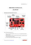
Typical Daisy Chain Configuration
5. Install the termination plugs.
•
There are 2 pairs of servo connectors on the NSC front panel, one above and one below the
LEDs. If one connector of a pair is used and the other unused, the unused connector have a
termination plug installed. If neither connector of a pair is used, it is not necessary to terminate
the pair. Termination plugs, however, may be used to seal the unused connectors.
•
The last servo in each chain must have a termination plug in the unused connector.
6. Connect the serial cable from the NSC to your host computer. If the NSC is equipped with an RS-232
port a straight-through serial cable is needed, and may be ordered as an option. If the NSC is equipped
with an RS-422 port the dual twisted-pair cable may be ordered as an option. Ensure that the cable is
wired appropriately for the pinouts of your host connector.
7. Reapply power. The NSC green LED should come on and stay on. The red LED should remain off.
8. Initiate communication with the NSC through a terminal emulation program or the demonstration
software supplied. See the NSC and servo command set for commands and queries.
2.2 Standalone RS-232 / Voltage Input Servos
1. Connect the power and voltage input signal or RS-232 host to the servo cables.
2. Plug the cables into the proper servo connectors.
3. Turn on system power. A new servo will center and hold that position in the absence of an input signal
or command from the RS-232 port. Position will change over +/- 45 degrees as a +/- 10V differential
signal is applied or position commands are issued over the serial port. The servo should echo serial
commands received.
Page 7 of 23
Acuity Technologies ISS User’s Manual
Rev 1.3
3. Component Descriptions
3.1 Servos
Case
Shafts
Aluminum, black anodized
Hardened steel
Diameter: ISS, 6 +0/-.03 mm. ISL, 10 +0/-.03 mm.
Gears
Steel
Sealed output and connectors
Position Feedback: 5000 count optical quadrature optical encoder on output shafts
Index and Home channels
Connectors: LEMO 1K series
Connector characteristics
Humidity (max):
Vibration:
Shock Resistance:
Salt Spray Corrosion:
Climatic Category:
Shielding (min):
Shielding (min):
IP Rating:
<=95% [at 60 deg C /140 F]
15 g [10 Hz - 2000 Hz]
100 g [ 6 ms]
>144 hr
50/175/21
95 dB (10 MHz)
80 dB (1 GHz)
66
3.1.1 Fault Protection
The IS Servos include built-in protection against possible fault conditions, including:
• Software error handling
• Status reporting for a large number of possible fault conditions
• Protection against conditions such as excessive temperature, under/over voltage, loss of commutation
signal, short circuits between the motor power outputs and between each output and power
input/return
• Recovery from loss of commutation signals and communication errors
3.2 Networked Servos
3.2.1 CAN Servo Connectors
The pinout and wire chart for both of the power plugs/cables on a networked servo are shown below. The
connectors are capable of carrying 7 amps on each of the 3 power and 3 ground pins.
Page 8 of 23
Acuity Technologies ISS User’s Manual
Rev 1.3
Servo CANbus/Power Connector Pinout
3.3 Standalone RS-232 / Voltage Input Servos
Servos ordered as standalone units can be controlled via RS-232 or a +/- 10V differential input signal.
They are configured via RS-232 commands. See the Servo Commands section of the Command Set
chapter.
3.3.1 Standalone Servo Connector Locations and Pinouts
ISL Servo
Standalone Servo Control Connector
3.3.2
ISS Servo
Standalone Servo Power Connector
Standalone Servo Analog Voltage Input
Maximum operating differential voltage
Maximum absolute differential input voltage
Differential input resistance
Analog input command resolution
±10V
± 16V
3.74 Kohms
14 bits
Using the Analog Input
To use the analog input to control position, speed, or torque, the serial command UM must first be used to
select the analog input as the control source and configure it as desired.
Driving the Analog Input with a Single-Ended Source
Page 9 of 23
Acuity Technologies ISS User’s Manual
Rev 1.3
To use the differential analog input with a single-ended source, AN+ should be connected to the signal
source and AN- to ground at the signal source location with a twisted pair.
3.3.3 Standalone Servo Home Input
Standalone servos may be moved to their hardware home location by applying 3.3 to 5 V to the H+ input.
H- is the return for the home signal and should be grounded. If the servo is enabled it will move to its
home position. The Home input has an internal 10K pulldown resistor.
3.4 Network Servo Controller
3.4.1 Servo Control
The NSC can control IS servos as well as smaller pulse width controlled servos driven by RC style pulses
(1-2 ms, 50-400 Hz). Up to 20 IS servos and 12 PWM servos may be connected.
3.4.2 Servo Power
IS servo power must be supplied on the main NSC power connector. This power also supplies the NSC’s
internal electronics and host serial port. The voltage input range is dependent on the version ordered.
3.4.3 Controlling PWM Servos
Power for any third Acuity or third party PWM servos must be applied to some of the V+ pins of AUX1
and/or AUX2 or supplied to servos separately. If less than 12 PWM servos are being driven, the unused
power/ground pins on AUX1 and/or AUX2 can be used as inputs. Maximum current is 3 Amps per pin.
The twelve power pins on AUX and AUX2 are connected together internally but isolated from the rest of
the NSC and may have 0 to 48V applied. AUX1 and AUX2 ground pins are connected to NSC ground.
3.4.4 Using PWM Input Signals
Signals from a servo controller such as an RC radio receiver can be used to control IS or PWM servos
attached to the NSC. Eight input pins on the AUX2 connector accept 1-2 ms PWM signals at up to 500
Hz. When pulses are received, the same width pulse is transmitted to the mapped servo channel if the
input has been mapped to a PWM address.
If the input has been mapped to an IS address, the command is interpreted as a torque, speed, or position
signal for that IS servo. In torque mode, pulse widths of 1 to 2 ms is mapped to a current range of +/- the
value specified in the last current limit command. PWM inputs outside the 1 to 2 ms range will be limited,
or clipped, to 1 or 2 ms before generating the servo signal. Servos are shipped with the current limit set
appropriately, so current limits should only be modified if reduction in peak torque is required.
Page 10 of 23
Acuity Technologies ISS User’s Manual
Rev 1.3
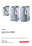
3.5 NSC Front Panel
The NSC connectors described below are mounted on the NSC front panel.
SERVO1
SERVO2
SERVO3
SERVO4
SERIAL1
SERIAL2
AUX1
AUX2
RS-232 or RS-422 Host Interface
Reserved: Do not connect.
4 PWM outputs, 8 PWM inputs
12 PWM outputs
POWER
Green Power LED
Red Status LED
NSC-60
NSC-20
NSC Front Panel
3.5.1 NSC Power Connector
The large power connector on the NSC-60 is capable of 30 Amps on each of its 2 power and ground pins.
The smaller power connector on the NSC-20 is capable of 10 Amps per pin.
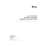
3.5.2 Cable Plug
The pinout of the plug on the power cable supplied with the NSC, looking into the cable plug (not the
mating NSC connector) is shown below.
60 Amp NSC Plug
20 Amp NSC Plug
Page 11 of 23
Acuity Technologies ISS User’s Manual
Rev 1.3
3.6 Serial and Auxiliary Input Connectors
Pinouts are shown below for the SERIAL1, AUX1, and AUX2 connectors.
NC
NC
NC
NC
Tx
CTS
RX
RTS
TxRXRX+
Tx+
NC
NC
NC
NC
SERIAL1 – RS-232 model
SERIAL1 – RS-422 model
PWM Output Address Map
Connector
AUX1
AUX1
AUX1
AUX1
AUX2
AUX2
AUX2
AUX2
AUX2
AUX2
AUX2
AUX2
Pin
1
2
3
4
1
2
3
4
5
6
7
8
Power Bus
Servo Address
21
22
23
24
25
26
27
28
29
30
31
32
AUX1 Power Pins: 10-13
AUX1 Ground Pins: 14-17, 19-22
AUX2 Power Pins: 10-16
AUX2 Ground Pins: 17, 19-26
Reserved: AUX1 pins 9,18, AUX2 pins 9, 18. Do not connect.
PWM Input Address Map
Connector
Pin Input Address
AUX1
5
1
AUX1
23
2
AUX1
6
3
AUX1
24
4
AUX1
7
5
AUX1
25
6
AUX1
8
7
AUX1
26
8
AUX 1
Page 12 of 23
AUX2
Acuity Technologies ISS User’s Manual
Rev 1.3
3.6.1 NSC Front Panel LEDs
The green LED will light when power is applied to the NSC. If the power light flashes, no servos are
detected. This is normal when no servos are connected. If it blinks when servos are connected it may be
due to improper network geometry or missing termination plugs.
The red LED is normally off. If the Red LED flashes, there is a servo error. The LED will flash the
number of times indicating the address (1 to 20) of the servo with a fault, pause, and repeat. If more than
one servo has a fault, the lower numbered servo will be indicated. Transient faults such as momentary
position errors may not be indicated, but will appear in status messages from the NSC to the host.
4. Command Set
4.1 NSC Commands
The NSC accepts commands for itself and the servos connected to it over the 232 or 422 serial port. The
commands in this section are executed by the NSC and may generate a sequence of commands to a servo.
Except for the Move Servo command, all commands are in ASCII. These consist of ASCII command
codes and command parameters.
The commands in the section Servo Commands have the same syntax and can be used with standalone
servos or in networked systems. In a networked system they are passed directly to the servos through the
NSC. The servo to which commands apply is specified with the SS (Select Servo) command.
Servo responses are relayed through the NSC. Servo heartbeats are followed by a two character servo
address identifier, from 01 to 32. Reponses to queries can be assumed to come from the currently selected
servo.
ASCII NSC commands consist of a two letter code which in some cases is followed by an [index]
specifier, an = sign, and a parameter value. Commands must be terminated by CR, LF, or semicolon.
AD[NN]
AP[NN]
EN
NR
NS
knabbbb…
SB=A
SS=AA
TS
UK
US
Set new servo address
Map PWM input to servo
NSC Echo on/off
Set/query NSC status reporting level
Query Network status
Move servo (binary command)
Set NSC baud rate
Select servo
Synchronize Time
Universal kill motor command
Universal stop motion command
4.1.1 NSC Command Descriptions
Set NSC Baud Rate
SB=A – Sets/reports the NSC host port baud rate. Valid values are
Page 13 of 23
Acuity Technologies ISS User’s Manual
Rev 1.3
0 = 4800, 1 = 9600, 2 =19200, 3 = 38400, 4 = 57600, 5 = 115200.
When the NSC or a serial standalone servo powers up, it looks for a stream of Space (ASCII byte code
32) characters at 9600 baud. If a stream of spaces is detected, it will set its baud rate to 9600, which is
also the default. If the first of a stream of 5 space characters is not detected within 250 ms, it will set its
rate to the value for which it has been configured and begin accepting commands. This allows a user to
establish contact with an NSC whose baud rate setting is unknown or does not match that of the host, by
powering it up while transmitting space characters or holding down the space bar when using a terminal
emulator set to 9600 baud. Note that an SV command must follow this command to make the change
permanent.
Baud rate of the CANBus cannot be changed.
EN Echo on/off
Set/query the NSC character echo mode. A parameter value of 1 turns NSC serial port character echo on,
0 turns echo off. May be turned off if local echo at terminal emulator is on.
knabbbb{nabbbb…} – Move Servos (Binary Command)
Sends a torque, speed, or position command to one or more servos, depending on the servo mode (Servo
SM command), and immediately executes the motion. This command is composed of binary values, so it
cannot be issued from a keyboard. It is used for high speed control of a servo network from a host control
program through the NSC. This command does not have a specific code. Rather, the first byte of the
command is a binary value specifying the number of CAN servos being commanded. Valid values are 120. This command causes the NSC to issue a TC, JV, or PA command followed by a BG command to the
specified servo(s) (not the servo presently selected with the SS command).
The second byte and (optionally) every 5th subsequent byte is a servo address. Valid values are 1-20. The
four bytes following each address are a position or speed value for that servo, depending on the mode of
the servo. A 4 byte value must follow each address, and the number of 5-byte address-parameter pairs
must match the binary value of the first byte of the command. The parameter is a 32 bit two’s
complement value representing the number of encoder counts for absolute or relative position mode, the
servo speed in encoder counts/second for speed mode, or the current in milliamperes for torque mode, per
the present value of SM for each servo addressed.
Replies: Servo ack or status according to the status reporting value for each servo and the NSC.
AD[NN] – Set New Servo Address
Seeks a servo attached to the CAN network with address NN, and changes its address to AA. The default
address for new servos is 127. As each new servo is added to a network, AD[127]=AA should be
performed to set its address within the range 01-20 before adding another new servo. Servos will retain
their addresses when moved from one network to another, so care must be taken to avoid conflicting
addresses.
Reply: The new servo address if it was successfully assigned, 0 otherwise.
AP[NN] – Map PWM Input to Servo
Maps PWM input NN to servo AA. NN is in the range 1 to 8, and AA in the range 1 to 32. If the servo
address is in the range 1 to 20, the 1 to 2 ms input is scaled to the configured position, torque, or speed
limits for that servo. If AA is in the range 21 to 32, the corresponding output PWM width and repetition
rate will track the input PWM signal with up to 1 ms delay.
Page 14 of 23
Acuity Technologies ISS User’s Manual
Rev 1.3
NR - Set/query NSC status reporting level
Set the way NSC status messages are sent to the host. This is distinct from the status reporting level for a
servo. In a network, each servo will report status to the NSC in accordance with its settings and the NSC
will always relay these messages, as it does all servo activity. (See the servo command SR.) The NSC
status configuration applies only to NSC status and error conditions.
Status reporting command parameters are formed from 3 digits. The first controls error reporting, the
second controls command acknowledgment, and the third controls periodic heartbeat transmission.
1XX: Send no NSC error or status messages to host.
2XX: Report NSC hard errors.
3XX. Report NSC hard and soft errors. (default)
X1X: Send no command acknowledgements.
X2X: Send an error message if NSC command is invalid. (default)
X3X: Send an ‘A’ acknowledgement to each valid servo command and an error message if invalid.
XX1: Send no ‘N’ heartbeat. (default)
XX2: Send ‘N’ heartbeat once every second.
XX3: Send ‘N’ heartbeat once every 0.1 second.
XX4: Send ‘N’ heartbeat once every 0.01 second.
XX5: Send ‘N’ heartbeat once every 0.001 second.
Error Codes:
50: Normal operation. Sent only in response to an NS command.
Soft Errors:
51: Can Bus Soft Error, retried successfully
Hard Errors:
52: Can Bus Hard Error
53: Servo Communication Failure – an expected response or heartbeat was not received
Error code 53 is followed by a 2 character servo address, 01 to 32.
NS – Query Network Status
Returns one of error codes 50-53.
Heartbeat
‘N’ – This is a single character message from the NSC, not a command. If status reporting level 3 is set,
this heartbeat acknowledgement is sent from the NSC to the host after each message. This provides
assurance that the NSC is functioning properly and receiving servo commands with a minimum of
communication overhead. The heartbeat consists of the letter N. This is acknowledgement that a motion
command has been received by the NSC, not an indication that the servo has received the command or
that motion has been completed. This is not the same as an individual servo ‘S’ heartbeat, which is
relayed through the NSC from a servo.
Select Servo
SS – Select a servo for subsequent configuration and motion control commands. Addresses of networked
servos must be two characters and must be in the range of 01 to 32. Upon power-up the default value of
SS in the NSC software is 127.
Synchronize Time
Page 15 of 23
Acuity Technologies ISS User’s Manual
Rev 1.3
TS – Set all servos time to the specified value, synchronized to within 100 microseconds. This can be
used with the BT command for multi-axis synchronized motion.
UK – Universal Kill Motor Command
When the NSC receives a UK command, it sends MO=0 commands to all CAN servos. This command
disables power to the motor, but the shaft may coast due to inertia.
US – Universal Stop Motion Command
When the NSC receives a US command, it sends a Stop Motion (ST) command to all CAN servos. The
ST command stops immediately and puts it into the position control mode. For a detailed description of
the SM commands, refer to the Servo Command Set documentation below.
4.2 Servo Commands
The IS servos use a 2 character motion control command set. The servo commands are the same whether
communicating directly with a Standalone IS Servo or with a Network IS Servo through the NSC, except
that servos must first have addresses assigned and a servo must be selected using the AD and SS
commands (described above) when using the NSC. When communicating with a standalone servo NSC
commands will have no effect.
Cautions
Note that several non-volatile servo parameters including current limits set with CL[N] are preset for the
IS servos. Exceeding the factory default values of these parameters may result in damage to the servo.
Standalone Servos
The following commands are interpreted and executed by the servos. In a networked system, they are
interpreted and relayed to the currently selected servo by the NSC. Any servo responses are relayed to
the host through the NSC.
BT
Begin motion at specified time
CL[N]
Motor current limitations
EC
Current error
EH[N], EL[N] Position and velocity error limits
ER
Last Error
ES
Servo Echo on/off
FD
Load factory default parameters from PROM
HL[N], LL[N] Jerk, acceleration, speed and position limits
HO
Move the servo to the hardware home location or stop homing
HV
Homing velocity
ID
Set/Report CAN node address
IN
Set/Report motion command input source
JV
Jog at constant velocity
KA
Acceleration feedforward gain
KF
Velocity feedforward gain
KP, KI, KD PID gains for servo control loops
LD
Load parameters from flash
MO
Motor enable/disable - necessary to change some configuration parameters.
Page 16 of 23
Acuity Technologies ISS User’s Manual
MS
PA
PE
PR
PU
PV
PX
RS
SR
ST
SV
TC
TM
TR
UB
VE
Rev 1.3
Motion status
Move to absolute position
Position error
Move to relative position
Power up behavior
Report present velocity
Report present position
Soft reset
Status reporting level
Stop motion immediately and hold position
Save parameters to non-volatile flash
Torque (motor current) command
System time
Target radius
Baud rate
Velocity error
4.2.1 Servo Command Descriptions
When using the motion control commands JV, PA, and PR, each motion mode starts with its entire set of
applicable parameters and limits HL[N] and LL[N]. Starting a point-to-point motion uses the present limit
settings of acceleration smoothing (jerk), acceleration/deceleration, speed, and position. Therefore these
parameters should be set to the desired values before initiating a motion.
Maximum magnitude of all parameters must be < 232-1 unless otherwise noted.
A few commands are available in binary format. Binary values of 2 bytes or more are in little endian.
abbbb – Move Servo (Binary Command)
Send a torque, speed, or position command. This command is composed of binary values, so it cannot be
issued from a keyboard. It is used for high speed control of a servo network from a host control program
through the NSC. The motor must be enabled (MO=1) for this command to have an effect. These moves
take place at once: They are not affected by the BT command. This command does not have a specific
code. Rather, the first byte of the command is a binary value specifying the type of motion commanded.
Valid values are 1-4. A 4 byte parameter must follow. The parameter is a 32 bit two’s complement value
representing the number of encoder counts for absolute or relative position mode, the servo speed in
encoder counts/second for speed mode, or the current in milliamps for torque mode.
First byte binary codes:
1: Absolute position
2: Relative position
3: Velocity
4: Torque (motor current)
Replies: Servo ack or status according to the servo status reporting control value.
BT – Set the time of execution of the next motion command
Starts the next PA, PR, JV, or TC command at the time specified, provided the specified time is after the
time of receipt of the BT command and the motion command. If the command has not begun executing
Page 17 of 23
Acuity Technologies ISS User’s Manual
Rev 1.3
by the time a second motion command is received the pending delayed command is removed. Sending
BT=0 will remove any pending delayed execution. See also TM.
Note: The servo time in milliseconds is a 32 bit value and will wrap around when the time value reaches
232-1 milliseconds. Users should ensure that this does affect operation of the BT command.
CL[N] - Current limits
Set the instantaneous peak and continuous current limits. Note that if these values are changed it is
possible to damage the motors in some servo models. If the continuous current limit is exceeded for more
than 2.7 seconds, the current will be reduced to the continuous current limit. If a motion command
attempts to drive the current above the peak current limit, the current will be limited to the peak current
limit.
CL[0] sets/reports the maximum peak current, in amperes. Valid limits are 0 to 6.6 amperes.
CL[1] sets/reports the maximum continuous current, in amperes. Valid limits are 0 to 3.3 amperes.
EB – Query error code binary
Reports the current error status of the servo as an ‘E’ character followed by a 32 bit binary long word.
Each error condition is reported with a corresponding bit in the long word set. See EC for error
descriptions.
EC –Query error code ASCII
Reports the current error status of the servo as an ASCII string of 32 ‘1’ or ‘0’ characters. Each error
condition is reported by one character.
Hard errors will shut down the drive. To re-enable the drive, ensure that the cause of the problem has
been corrected before re-enabling it by sending the MO=1 command.
Error Codes
Normal operation
0000 0000 0000 0000 0000 0000 0000 0000
Hard Errors
Hard CAN bus communication failure
Power circuitry short
Temperature limit exceeded
Power supply failure
Under voltage
Over voltage
Power up reset occurred
Motor commutation failure
Unknown Amplifier Error
EEPROM Read Error
0100 0000 0000 0000 0000 0000 0000 0000
0010 0000 0000 0000 0000 0000 0000 0000
0001 0000 0000 0000 0000 0000 0000 0000
0000 1000 0000 0000 0000 0000 0000 0000
0000 0100 0000 0000 0000 0000 0000 0000
0000 0010 0000 0000 0000 0000 0000 0000
0000 0001 0000 0000 0000 0000 0000 0000
0000 0000 1000 0000 0000 0000 0000 0000
0000 0000 0100 0000 0000 0000 0000 0000
0000 0000 0010 0000 0000 0000 0000 0000
Short, Commutation, and Over-temperature errors, require disabling the motor (MO=0) or power cycling
the servo to restore operation.
Soft Errors
Bad command code received
Bad parameter value received
Continuous or peak current limit triggered
EEPROM Write Error
0000 0000 0000 0000 0000 0000 0000 0001
0000 0000 0000 0000 0000 0000 0000 0010
0000 0000 0000 0000 0000 0000 0000 0100
0000 0000 0000 0000 0000 0000 0000 1000
Page 18 of 23
Acuity Technologies ISS User’s Manual
Soft CAN error – transmission retried
Position following error
Speed following error
Position limit error – At or beyond limits on motion
Speed limit error – At or beyond limits on motion
Rev 1.3
0000 0000 0000 0000 0000 0000 0001 0000
0000 0000 0000 0000 0000 0000 0010 0000
0000 0000 0000 0000 0000 0000 0100 0000
0000 0000 0000 0000 0000 0000 1000 0000
0000 0000 0000 0000 0000 0001 0000 0000
EH, EL – Error High, Low Limits
Set/report the error level at which a soft position or speed error will be reported.
EL[1] = Lower speed error limit
EL[2] = Lower position error limit
EH[1] = Higher speed error limit
EH[2] = Higher position error limit
Lower limits must be < 0, Higher limits > 0.
ER – Latched Errors
Reports/clears errors detected in the current power cycle since the last time ER was cleared. In the case of
transient errors such as a CAN bus soft error, this value will be retained after the error condition has
corrected. ER=0 will clear the retained errors. See EC for list of error bits
ES – Echo on/off
A value of 1 turns NSC serial port character echo on (default), 0 turns echo off. An alternative to local
echo at terminal emulator.
FD – Load factory default parameters from PROM
Reads the factory servo parameters from non-volatile memory and set the active parameters to the
retrieved values. See also SV and LD.
HL[N], LL[N] – Jerk, acceleration, speed and position limits
Positive and negative values for motion limits. HL[N] sets/reports the positive limit for each, and LL[N]
the negative limit.
N=1
N=2
N=3
N=4
Jerk, in encoder counts/sec3
Acceleration, in encoder counts/sec2
Speed, in encoder counts/sec
Position, in encoder counts
Jerk is defined as the rate of change of acceleration.
For all except position, lower limits must be < 0, Higher limits > 0.
For position, lower limits must be <= 0, Higher limits >= 0. Setting both to zero allows unlimited rotation.
Position limits and speed limits are enforced in all types of motion.
Acceleration and jerk limits are enforced only in PA and PR moves. The jerk limits are used to set the
rate of acceleration in PA and PR moves.
The position and speed limits are enforced in three ways. First, a position or speed motion command with
a parameter that exceeds the limits will be rejected as invalid. Second, path planning is performed such
that if the planned trajectory will cause commanded speeds or positions outside the limits, the trajectory is
altered. Third, actual speed and position are checked at 1 millisecond intervals and commanded motor
Page 19 of 23
Acuity Technologies ISS User’s Manual
Rev 1.3
power is limited to generate only those motor currents that will accelerate away from the limit reached.
For example, reaching a positive limit will clip (signed) commanded motor current to zero or less.
It is possible for an external force or inertia to carry the speed or position past the limits set: No power is
applied to the motor for enforcing limits.
HO – Home
Reports whether the servo is homing, or moves the servo to the encoder home location (HO=1) and then
sets the servo position to zero, or stops homing (HO=0). Servos may be configured to home on power up,
or only on receipt of this command.
HV – Home velocity
Sets/reports the speed at which the servo will home. Range: > 0 and within the velocity limits in
presently in effect.
ID – CAN node address
Sets/reports the CAN address of the servo, from 1 to 127
IN - Motion command input source
Sets/Reports motion command input source. The serial port remains active for configuration and other
commands.
1: Serial port
2: Analog Input
3: PWM Input
JV – Jog at constant velocity
Reports last JV commanded, or ramps to the specified velocity, in encoder counts/second, and continues
until the next motion command is received or a position limit is exceeded. Uses the jerk and acceleration
limits to reach the commanded velocity. JV=0 will stop using these limits. To stop immediately and hold
position, use the ST command. See also PV for actual velocity.
KA – Acceleration feedforward gain
Applies a motor current proportional to the instantaneous commanded speed in position control in
addition to the KF and PID output current. This can be used to improve transient response in systems with
large inertial loads. This parameter only has an effect in PA and PR commands, and their binary
equivalents.
KF – Velocity feedforward gain
Applies a motor current proportional to the commanded speed (JV) or to the instantaneous speed in
position control in addition to the KA and PID output current. This can be used to improve transient
response in systems with a high degree of mechanical speed-proportional damping. This parameter only
has an effect in JV, PA and PR commands, and their binary equivalents.
KP, KI, KD - Servo Proportional-Integral-Derivative gains
The IS servo controllers implement PID control with an optional feedforward term. The controllers and
motors are tuned to perform well with most loads. For highly inertial loads it may be appropriate to
reduce the proportional and integral terms to reduce overshoot or oscillation. These parameters can be
read and adjusted through the KP, KI, KD, KA, and KF commands.
Page 20 of 23
Acuity Technologies ISS User’s Manual
Rev 1.3
Warning: Changing these parameters can result in violent unstable motor motion. We recommend setting
low limits for maximum positive and negative motor current before experimenting with these values.
Keep in mind that the position, speed, acceleration, and current limits can affect servo dynamics for large
movements. Test stability with small motions before trying large movements or high speeds.
LD - Load Parameters from Flash
Reads the stored servo parameters from non-volatile memory and set the active parameters to the
retrieved values. See also SV and FD.
MO - Enables and disables (freewheels) motor power
MO=0 disables the motor. This is the idle state of the drive. The power stage is disabled and no current
flows in the motor. MO=1 is the operative state of the servo drive, driving the motor and activating and
executing the programmed motion. When first enabled, the servo holds its current position. MO=1 must
be given before a motion command will move the servo. If MO is set to 1 and the motor is already on,
nothing happens. MO is set to zero when a hard error occurs. See the EC error status query.
Note:
When PU=1 or PU=2 the servo drive will attempt to start (set MO=1) automatically after power on.
MS - Motion Status
Query the current status and target value. Responses are:
In JV command (JV=speed)
In PA command (PA=destination)
In PR command(PR=target)
In TC command(TC=torque)
Holding position (HL=position)
Homing (HO=1)
Motor off (MO=0).
MS is a query command only. Any parameter is ignored.
PA - Absolute Position
Reports last PA commanded, or commands motion to the specified target position. If a PA, PR, JV or TC
command is being executed, is aborted and the motion takes place immediately. The drive moves to the
desired target position as fast as possible, subject to the jerk, speed, and acceleration limits. See HH and HL
commands. See also PR (Relative Position).
PE - Position Error
Reports the current position error when the motion status is (MS) is PA, PR, JV or HL. This is the error in
the PID motion control loop, not the difference between the target location of a PA or PR command and
the present location.
PR - Command Relative Position
Reports last PA commanded, or moves the distance specified from the current position. If a PA, PR, JV or
TC command is being executed, is aborted and the motion takes place immediately from the current
encoder position. If the servo is holding at a target location the relative move will be from the target
location, not the current location which may differ from the target by a holding error. The drive moves to
the desired target position as fast as possible, subject to the jerk, speed, and acceleration limits: See HH and
HL commands. See also PA (Absolute Position).
PU– Power Up Behavior
Page 21 of 23
Acuity Technologies ISS User’s Manual
Rev 1.3
Configures the servo’s power up behavior. Valid parameters are
0: Do not activate the motor on power up. Servo will not engage until a motion or HO command is
received. Zero position is the encoder position when the servo engages. This is the default.
1: Activate the motor, causing it to hold position, but do not move to home on power up.
2: Activate the motor and home the servo, setting the encoder value to 0 at the home location.
PV – Report Present Velocity
Reports the present velocity in encoder counts per second. This is an average of the velocity over the previous
10 milliseconds. This may be noisy and of low resolution at low speeds.
PX – Report Present Position
Reports the present position in encoder counts.
RS - Soft Reset
Restarts the servo as if from power up.
SR – Status Reporting Level
Set the way servo status messages are sent to the host. This is distinct from the status reporting level for
the NSC. In a network, each servo will report status to the NSC in accordance with its settings and the
NSC will always relay these messages, as it does all servo activity. (See the NSC command NR.)
Status reporting command parameters are formed from 3 digits. The first controls error reporting, the
second controls command acknowledgment, and the third controls periodic heartbeat transmission.
1XX: Send no error messages to host.
2XX: Report hard servo errors only (default).
3XX. Report hard and soft servo errors.
X1X: Send no command acknowledgements.
X2X: Send an error message if servo command is invalid (default).
X3X: Send an ‘S’ acknowledgement to each valid servo command or an error message if invalid.
XX1: Send no ‘K’ heartbeat (default).
XX2: Send ‘K’ heartbeat once every second.
XX3: Send ‘K’ heartbeat once every 0.1 second.
XX4: Send ‘K’ heartbeat once every 0.01 second.
XX5: Send ‘K’ heartbeat once every 0.001 second.
Standalone Servo Heartbeat: Single ‘K’ character sent over serial port.
Network Servo Heartbeat: 5 bytes: 1 byte CAN ID followed by ‘EE99’.
See the EC command for error code meanings.
ST - Stop motion immediately and hold position
Emergency stop and hold position. Decelerates as allowed by the peak current limit and hold position
when stopped. To stop using the motion smoothness parameters, use the JV=0 command. To disable
motor power immediately, use the MO=0 command.
SV - Save parameters to non-volatile flash
Saves the currently active servo parameters to non-volatile memory, overwriting the stored values. Does
not affect the factory default values. See also LD and FD.
Page 22 of 23
Acuity Technologies ISS User’s Manual
Rev 1.3
TC - Torque (motor current) command
Direct control of motor current. Valid command values are – CL[0] to CL[0].
TM - System Time
Set/report the servo time. If the time is not set, the servo’s time is in milliseconds from power up. System
time is not preserved across power cycles.
Note: The servo time in milliseconds is a 32 bit value and will wrap around when the time value reaches
232-1 milliseconds. Users should ensure that this does affect operation of the BT command.
TR - Target Radius
Set/report the distance from position target for deciding that a motion is complete when executing a PA or
PR command. Range is 0 to 65535. The MS query will return “Holding position” once the servo has
arrived within this radius of the target position and the speed has reached zero. The MS state will not
change until the next motion command regardless of motion from external disturbances. The holding
error can be read using PE.
UB – Baud Rate
Set/report the current baud rate in serial interface servos.
Values are
0: 4800 Baud
1: 9600 Baud
2: 19200 Baud
3: 38400 Baud
4: 57600 Baud
5: 115200 Baud
Baud rate of CANBus servos cannot be changed.
5. CD Directory Structure
The NSC and servos come with a CD with the following contents:
\doc
\bin
\src
-This users guide and servo datasheet
- precompiled GUI-driven demo for Windows XP host
- host demo program source code and MS C/C++ solution
6. Servo Interface Application
The Acuity Servo Interface for Windows XP is an interface for communication through a serial port with
the NSC or with a standalone servo is found in the \bin directory of the distribution CD. This provides a
simple interface for configuring servos and trying out motion commands.
Page 23 of 23