1
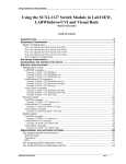
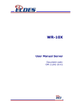
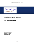
SRI-500
User’s Manual
Rev. 2.0
September 30, 2015
Acuity Technologies
3475 Edison Way Bldg P
Menlo Park CA 94025
www.acuitytx.com
Page 1 of 17
TABLE OF CONTENTS
1.
OVERVIEW .......................................................................................................................................................3
2.
HARDWARE POWER UP ...............................................................................................................................3
2.1
2.1
2.2
2.3
3.
POWER/SIGNAL CONNECTION .....................................................................................................................3
SCANNING OPERATION ................................................................................................................................3
USE AND MAINTENANCE .............................................................................................................................5
AZIMUTH MOTOR PATH PLANNING .............................................................................................................5
SOFTWARE AND DOCUMENTATION........................................................................................................6
3.1
SOFTWARE INSTALLATION UNDER XP AND WINDOWS 7 .............................................................................6
3.2
OTHER OPERATING SYSTEMS ......................................................................................................................6
3.3
RUNNING THE DEMO EXECUTABLE .............................................................................................................6
3.3.1
Ethernet Connectivity ............................................................................................................................6
3.3.2
Making a Scan .......................................................................................................................................7
3.3.3
Displaying a Scan ..................................................................................................................................7
4.
DEVELOPING APPLICATIONS WITH THE DEMONSTRATION SOFTWARE..................................9
4.1
COMMAND INTERFACE ................................................................................................................................9
4.1.1
List of Interface Functions for Sending Scanner Commands.................................................................9
4.1.2
Constants and Data Structures in the Demo Software.........................................................................10
4.1.3
Command Acknowledgement Status Values ........................................................................................10
4.2
DESCRIPTIONS OF COMMANDS ..................................................................................................................10
4.2.1
Scan Setup: Scan Window and Speed Commands ...............................................................................10
4.2.1
Scan Initiation......................................................................................................................................11
4.2.2
Positioning Commands........................................................................................................................11
4.2.3
Commands for Terminating Scanning .................................................................................................11
4.2.4
Sleep Command ...................................................................................................................................12
4.2.5
Status and Scanner State Commands...................................................................................................12
4.2.6
Other Useful Functions in the Demo Software ....................................................................................12
4.3
SRI-500 DATA SHEET, FOLLOWING PAGES.................................................................................................13
Page 2 of 17
1. Overview
The SRI-500 Scanning Rangefinding Imager consists of a pulse laser rangefinder, a turret mounted
scanning mirror, and a processor with 100 Mbit Ethernet for SRI-500 to client communications. The
SRI-500 operates by measuring the time difference between a transmitted laser pulse and a received laser
pulse and deflecting a high-speed mirror in azimuth and elevation to scan a field up to 130 degrees of
elevation with unlimited azimuth rotation. The azimuth and elevation fields of view for each scan may be
defined allowing rapid transitions between fast panoramic scanning and detailed scanning of areas of
interest.
2. Hardware Power Up
2.1 Power/Signal Connection
The SRI-500 requires 11 to 18 Volts (12V nominal) and is designed to draw from an automotive or
similar power system. The supply must be capable of up to 30 amps burst (0.1 sec) and 15 amps
continuous. Wire the power supply to the connector cables and plug in the connector with the power
switch off. Connect the SRI-500 ethernet jack to a hub, router, or access point with a CAT-5 Ethernet
cable or to a client machine with a crossover cable, and then turn on the scanner.
Pin A: Ground. Black Cable Wire
Pin B: No Connection
Pin C: No Connection
Pin D: Power. Yellow / Green Cable Wire
A few seconds after power up the turret will seek center and stop with the optical axis aligned with one
edge of the scanner housing. The turret window is not aligned with the optical axis, so the window will be
?
at a 10 angle to the housing. The scanner emits a short beep a few seconds later, after power up testing
and initialization is completed.
2.1 Scanning Operation
The SRI-500 acts as a scan data server for a client machine that communicates through a set of commands
transmitted via Ethernet using TCP-IP. A scan is 1 or more nearly vertical lines of range data. The SRI500 acquires and transmits scan data in response to scanning commands transmitted to it from the client.
The vertical scans occur at high speed while the azimuth angle of changes relatively slowly. Vertical lines
are actually slightly sloped, dependent on the horizontal and vertical scan speeds set by the client.
Page 3 of 17
Each vertical line in a scan consists of 1 to 3000 range measurement points. The laser pulse rate is
controlled by the elevation motor speed and the scan line sample spacing. The sample spacing is the
number of elevation encoder counts between laser pulses (range samples). The maximum laser pulse rate
is 800,000 per second. Attempting to set a combination of motor speed divided by sample spacing equal
to more than 800,000 will result in an error. The maximum sample spacing is 20, and the minimum is 1
(subject to the maximum sample rate limit). The minimum elevation motor speed for a scan is 100,000
encoder counts per second, and the maximum is 2,400,000 counts per second with a sample spacing of 3
or more. The elevation motor speed may be set to zero with the Immediate Elevation Speed command.
Scan data comes from the SRI-500 via Ethernet using TCP. Each vertical scan line consists of a line
header followed by scan data points. The header includes information about the scan line such as the
vertical and horizontal start positions and the number and spacing of the samples. Each sample contains a
16 bit range value, a16 bit signal strength, a 16 bit reserved word and a 16 bit low order azimuth motor
encoder value. This can then be converted to Cartesian coordinates by client side software included with
the scanner.
Scan data accuracy will stabilize after a warmup time of approximately 5 minutes. The scanner takes
several seconds to drain the power supply when turned off. To power cycle the scanner, leave the switch
off for several seconds. If the scanner turret does not move through its power up cycle, or if it does not
issue a short beep a few seconds after finishing the turret motion, or if the client cannot send commands
and receive command acknowledgements the scanner may need to be turned off for a longer time.
The minimum target range for correct distance measurement is approximately 5 feet. If an object is in the
scan field at a closer distance, it may be unseen, or an incorrect, longer range may be indicated for it.
If no target is detected after the time required for a signal to return from a surface 500 feet away, a time
out signal ends the ranging interval. A range indication of approximately 500 feet should be considered a
“no return” indication, regardless of the signal strength associated with the measurement.
The maximum distance at which an object will reflect a measurable return signal depends on the
reflectance of the object and the amount of ambient light present. The greatest distances are obtained with
light colored objects during times of low lighting, such as on cloudy days or when the sun is down.
The variation in the indicated range to a surface depends on the strength of the signal returned from the
target. For a strong signal the standard deviation of the measured range is approximately 1.5 inches.
Ranges are transmitted to the client in “raw” form, before correcting for signal strength, temperature, zero
offset, and scaling. The demonstration program performs these calibration corrections when the scan data
is converted from a binary scan file to XYZ data for display.
The laser beam has an initial diameter of about 1 inch, so this is the best lateral resolution of the system at
short range. The resolution of the azimuth encoder is about 0.35 milliradians, some 7 times better than
the horizontal divergence of the laser beam, so the horizontal scan rate may be set to traverse several
counts per vertical scan line unless overlapping data is desired. The vertical resolution is 0.65 milliradians
per encoder count (accounting for angle doubling from the mirror reflection), which is comparable to the
vertical beam divergence.
Note that the optical axis is offset 10 degrees from the direction the window is facing. Thus what appears
in the scan data will be shifted from the apparent window orientation.
Page 4 of 17
2.2 Use and Maintenance
The SRI-500 is a rugged system designed for use on mobile platforms. However, it should be protected
from severe shock and vibration, such as that which might be experienced on a vehicle without
suspension or with high engine vibration. In these cases the scanner should be mounted with shock
absorbing mounting feet or pads. Lift the scanner only by the base, not by the turret.
The motors for the turret and scanning mirror are brushless DC motors which will not generally need
maintenance over the life of the scanner. The scanner turret is filled with dry nitrogen and sealed to
prevent condensation and corrosion. Do not open the scanner or break any seals. Doing so will necessitate
factory repair.
The front window is IR transparent filter glass, and should be kept clean and free of scratches and dirt.
There is a rotary seal under the turret which should be lubricated with the provided light mineral oil
lubricant if the turret sticks or “grabs” when rotated by hand with the power off. Some stiffness after
periods of non-use are normal and do not require re-lubrication if the turret moves freely after a few backand-forth oscillations by hand. To lubricate, insert the tip the lubricant dispenser tube under the edge of
the turret until slight resistance is encountered and squeeze a small amount of lubricant out, preferably
with the scanner tilted and lubricated from the high side. Turn the turret by hand through a few rotations
until it rotates smoothly. Slight variation in resistance at different angles is normal.
2.3 Azimuth Motor Path Planning
The turret of the SRI-500 moves through scans at constant speed. To accomplish this, the SRI-500
performs intelligent path planning which moves the azimuth motor into the correct position and speed for
the commanded scan. While one scan is executing, another may be queued so that the next scan may be
anticipated by the path planning algorithm immediately upon completion of the prior scan. Turret
positioning and speed commands are also available to preposition the turret for quick scan response.
Page 5 of 17
3. Software and Documentation
The SRI-500 comes with the following software and documentation:
This user’s guide.
Precompiled client for Windows XP / Windows 7.
Client side demonstration source code, tested with MS Visual C++. This is intended as a guide
for software development, not a full-fledged application.
3.1 Software Installation under XP and Windows 7
The SRI-500 installation program does not need to installed, and may be executed directly after copying
to disk. The software has been developed as a “solution” using Microsoft Visual C++ 2008 in XP. An
executable version of the program has been tested successfully under Windows 7.
3.2 Other Operating Systems
The source code provided may be used as the basis for building applications under other operating
systems, though the OS specific user interface has only been implemented under Windows.
3.3 Running the Demo Executable
SAFETY WARNING: The turret will move rapidly and laser light is emitted from the window during
demonstration program operation. Although the SRI-500 laser output is safe in normal operation, care
should be taken to avoid circumstances that might result in injury or damage. Ensure that the turret is free
to move and that the system is firmly seated on a level surface. Do not look into the window using
magnifying optics.
The demonstration software may be executed by double-clicking BasePCGUI.exe in the top level
directory of the demo software package supplied.
3.3.1 Ethernet Connectivity
It is recommended that the scanner be used on a 100 Mbit ethernet link with minimal other activity since
the SRI-500 can use a substantial portion of the bandwidth of this link depending on the sampling speed
selected. Wireless network connection is not recommended due to wide variation in wireless data rates.
If you connect the scanner and client computer to a network with a DHCP server, the scanner will get an
IP address from it. Otherwise it will start with an IP address of 192.168.1.191. The scanner and client use
ports 9760 and 9761 for command/ack and data transfer.
After power up it typically takes several seconds for the network router or client to detect the scanner so
that it is visible to other systems, sometimes longer depending on the router and network configuration.
Page 6 of 17
The client Windows software connects to the scanner using the “SRI500” host name of the scanner. For
connecting the scanner directly to a PC with no router or switch, use a crossover CAT-5 / CAT-6 Ethernet
cable. For direct connection, the client PC must be configured to use a pre-assigned IP address such as
192.168.1.70 to enable it to communicate with the scanner. This can be done from the Windows Network
Connections -> Local Area Connection (x) -> TCP-IP -> Properties dialog. The demo software will then
be able to initialize the machine’s network interface and connect with the scanner without a router/DHCP
server.
The message monitor window that opens with the startup of the supplied software will display a series of
messages, shown below, when the scanner has been successfully connected with the software via two
TCP sockets.
3.3.2 Making a Scan
To scan with the demo software once the Ethernet link is established, the scan parameters must first be
sent to the scanner. Parameters for a 360 degree scan have been coded into the demo and appear as the
default values in the ‘Scan Line Setup’ and ‘Scan Azimuth Setup’ input groups in the upper left of the
interface panel. Click the Send Scan Line Parameters and the Send Scan Azimuth Parameters buttons. In
each case the response COMMAND_RECEIVED_AND_ACK'D response code should appear in the Command
Acknowledgement box.
Click ‘Queue Single Scan’. The turret will rotate rapidly to the azimuth start position and the turret will
rotate at the specified speed to the azimuth stop position and then stop.
3.3.3 Displaying a Scan
After the scan is complete the scan data may be displayed in perspective view with ‘Calibrate, Transform,
and Display last Captured Scan’. The view may be rotated, panned, and zoomed using the left, center, and
right mouse buttons.
Page 7 of 17
The Distance, X, Y, and Z limit filters can be used to filter out unwanted data. These can be used to look
at “slices” of scans or to remove noise or uninteresting distant points. Scans typically contain some
spurious points where the signal strength or range are not within valid limits. For example, if no signal is
detected a maximum range value is returned. Some filtering also occurs in the demonstration software;
see the discussion below.
Page 8 of 17
4. Developing Applications with the Demonstration Software
4.1 Command Interface
The demonstration program provides a simple GUI for testing the scanner and performing scans. The
Windows version was compiled with Microsoft Visual C++ 2008. It demonstrates the SRI-500 API and
programmable modes. The client demonstration software include routines for converting range, azimuth
and elevation counts, and signal strength to corrected range, target reflectance, and Cartesian coordinates
with the scanner at the origin.
The Application Programming Interface to the SRI-500 consists of commands that set SRI-500 operation
modes and parameters and perform scanning sequences. When a command function is called, a command
packet is sent to the scanner. The scanner will acknowledge each command after validating the
parameters. Commands that take time to implement, such as setting a motor speed, will be acknowledged
before the commanded condition is obtained. The client software should wait for an acknowledgement of
each command before sending another.
The demo software also contains routines for transforming and calibrating scan data and for displaying it
using OpenGL. OpenGL must be installed on a machine for the display software to function, and is
typically included on Windows systems. The appropriate version will depend on the computer and
graphics hardware being used.
4.1.1
List of Interface Functions for Sending Scanner Commands
Each function’s parameter list starts with a scanner handle. Currently only scanner zero is supported.
Each function returns the status returned by the scanner with the command acknowledgement. The source
code for these functions is located in scannerFunctions.cpp. See the “Descriptions of Commands” section
for details.
int elevationParameters(ScannerClass *scanner, int elevationSpeed, int
elevationStart, int samplesPerLine, int elevSampleSpacing)
int azimuthParameters(ScannerClass *scanner, int azimuthSpeed, int
azimuthStart, int azimuthEnd)
int startScan(ScannerClass *scanner)
int elevationSpeed(ScannerClass *scanner, int elSpeed)
int azimuthSpeed(ScannerClass *scanner, int azSpeed)
int azimuthPosition(ScannerClass *scanner, int azPos)
int haltScan(ScannerClass *scanner)
int abortScan(ScannerClass *scanner)
int getStatus(ScannerClass *scanner)
int scannerSleep(ScannerClass *scanner)
Page 9 of 17
int calibrateScan(ScannerClass *scanner)
int getLog(ScannerClass *scanner)
4.1.2
Constants and Data Structures in the Demo Software
The file datapackets.h in the demonstration source contains definitions that are shared between the
scanner and the client software. These include the command packet, scan line header and point data
format definitions, and command, error, status and scanner state codes This file should not be altered.
4.1.3
Command Acknowledgement Status Values
Each command acknowledgement returns a status value indicating whether the command was valid and
whether it was initiated successfully. These are listed in datapackets.h as internal scanner error codes,
invalid command and parameter error codes, and warning codes. In addition, the present scanner state can
be obtained using getStatus().
4.2 Descriptions of Commands
4.2.1 Scan Setup: Scan Window and Speed Commands
The horizontal and vertical speeds of the scans and the scan start and stop vertical and horizontal
locations are based on the internal scanning motor encoder counts. The vertical scan resolution is 22.755
counts per degree of optical scan angle (16384 counts per elevation motor rotation). The beam deflection
angle is double the mirror deflection angle for the vertical only. The horizontal resolution is 16000 counts
per 360 degrees of optical scan angle.
Before a scan can be executed, the vertical and horizontal scan parameters must be set. So that the scanner
can validate the parameters immediately, groups of relevant parameters are sent with one command. The
parameter values are stored and used for all subsequent scans until changed.
int elevationParameters(ScannerClass *scanner, int elevationSpeed, int
elevationStart, int samplesPerLine, int elevSampleSpacing)
This command sets the speed of the vertical (elevation) scan mirror, the vertical encoder location at which
laser ranging starts, the number of sample points taken, and the number of encoder counts between each
sample for each vertical scan line. Valid speeds are 10000 to 2400000 encoder counts per second. Since
the maximum laser pulse rate is 800,000 points per second, the sample spacing at high motor speeds
(above 800000) must be greater than 1 or an error will result.
int azimuthParameters(ScannerClass *scanner, int azimuthSpeed, int
azimuthStart, int azimuthEnd)
This command sets the speed of the horizontal (azimuth) turret motor and the horizontal encoder location
at which the scan starts and ends. The speed must agree with the implied scan direction. Valid speeds are
Page 10 of 17
+/-100 to +/-48000 counts per second. Valid start and stop locations are -2000000000 to 2000000000.
The zero location is the orientation of the turret after power up or after a sleep command has been
completed.
4.2.1 Scan Initiation
int startScan(ScannerClass *scanner)
This command starts a scan. The mirror speed is first set to that specified in the last elevationParameters
command. The turret then moves to enter the scan at the specified scan speed and location using path
planning and the scan occurs at constant speed. This command may be given while a previous scan is still
in progress. The command will be buffered and execute when the previous scan completes, so that
scanning can be continuous. Only one scan may be buffered.
If no buffered scan is pending when a scan completes, the turret will stop. The mirror remains spinning
unless stopped with a sleep or elevationSpeed command.
4.2.2 Positioning Commands
int elevationSpeed(ScannerClass *scanner, int elSpeed)
Sets the mirror speed. The valid ranges are 0 and 100000 to 2400000 counts per second. This may be used
to stop the mirror after a scan or to bring the mirror to speed in order to reduce the delay between a scan
command and initiation of the scan.
int azimuthSpeed(ScannerClass *scanner, int azSpeed)
Sets the turret speed. The valid ranges are -48000 to 48000 counts per second. This may be used to move
the turret at a controlled speed between scans.
int azimuthPosition(ScannerClass *scanner, int azPos)
Sets the turret position. The valid ranges are -2000000000 to 2000000000. This may be used to position
the turret between scans. The turret moves at up to +/-48000 encoder counts per second.
4.2.3 Commands for Terminating Scanning
int haltScan(ScannerClass *scanner)
Halts scanning at the end of the current scan line. Stops the azimuth motor. Scans queued prior to the
Halt Scan command are flushed without execution.
int abortScan(ScannerClass *scanner)
Page 11 of 17
Aborts the current scan at the end of the current scan line. Stops the azimuth motor. This command is
processed asynchronously so that any scan in progress is aborted before completion. Scans queued prior
to the Abort Scan command are flushed without execution.
4.2.4 Sleep Command
int scannerSleep(ScannerClass *scanner)
Stops the elevation motor. Moves the turret to the zero location and stops the azimuth motor. Zeros the
azimuth location counter.
4.2.5 Status and Scanner State Commands
int getLog(ScannerClass *scanner)
Gets and prints out various information about the current scanner condition. This command may not be
used while a scan is in progress and will return an error code in that case. Some of this information is
diagnostic and will help Acuity determine if there is a scanner malfunction. The temperature information
reported is the temperature at the end of the last scan. Temperature is not updated between scans.
int getStatus(ScannerClass *scanner)
Gets a single value representing the present scanner state, such as ready, scanning, or error halt. See the
scanner state values in datapackets.h for the list of scanner states. Unlike getLog, this command may be
used while a scan is in progress.
4.2.6
Other Useful Functions in the Demo Software
pushTCPCommand(ScannerClass *scanner)
Used by the command interface functions above to send commands to the scanner and receive command
acknowledgements.
ScannerClass::logBinaryScanLine(SRIPacket *packet, int fnum)
Writes a raw (uncalibrated) line of scan data to disk. This simple routine is fast enough that it may be
used during a scan to save each line in real time without losing data on most computers.
calibrateLine(SRIPacket *packet, calibratedLine *calLine)
Applies calibration algorithms to the raw scan data to obtain distances in inches and angles in radians, in
spherical coordinates. Calibrations for temperature, signal strength, scanning mirror geometry, electronics
timing offsets, and speed of light are implemented.
Page 12 of 17
ScannerClass::CalibrateAndConvertToAscii()
Applies calibrateLine() to each line of a binary scan file and creates an ASCII file with calibrated
spherical coordinate data.
ReceiveDataClass::ReceiveDataClass(ScannerClass *sptr)
Receives command responses and scan line data from the scanner. Signals the command interface
(pushTCPCommand())when a command acknowledgement is received. Command acknowledgements
are send in standalone packets when the scanner is not sending scan line information and are embedded in
the header of a scan line packet when scans are in progress.
ScannerClass::ScanToXYZ()
Reads a raw scan data binary file and calibrates each line, and then generates XYZ points for display.
Uses the openGL routine oglDrawScene().
4.3 SRI-500 data sheet, following pages.
Page 13 of 17
SRI-500
Scanning Laser Rangefinder with Inertial Image Stabilization
The SRI-500 Laser Rangefinder is an omnidirectional scanning range
image acquisition system for obtaining range images from stationary
or mobile platforms at distances up to 500 feet and 800,000 points
per second. Scanning is a combination of fast vertical scans at 439
o
lines/s combined with an azimuth sweep rate of up to 1080 /s.
3D point datasets are acquired by setting vertical and horizontal
sweep rates, and commanding acquisition of a sequence of vertical
scan lines through a specified elevation and azimuth range. The SRI500 can be programmed to auto-cycle through an azimuth region
repeatedly, automatically reversing direction.
The SRI-500 communicates with a host via a TCP-IP connection. The host may issue Laser
Enable, Motor Speed, and Take Scan commands through software based on sample source code
provided with the scanner. Each scan consists of a sequence of nearly vertical scan lines taken
between start and stop platform azimuth and elevation angles. Elevation coverage may be
o
o
programmed from +65 to -65 with unlimited continuous azimuth rotation.
Optional Inertial Measurement Unit
In mobile applications, the optional internal
inertial measurement unit captures platform
vibration and rotation at 200 Hz and is used to
correct the 3D coordinates of each sample point
create a stabilized world referenced dataset.
Data for each scan is corrected to the initial
platform inertial orientation during acquisition.
Platform orientation and velocity changes
between and during scans are reported with each
scan, so multiple scans may be registered in a
world map and vehicle motion may be derived.
to
In static applications the internal IMU may be used to register earth vertical which provides absolute
orientation information for structures captured.
Acuity Technologies Inc. 3475 Edison Way Bldg P. Menlo Park, CA USA 94025 650-369-6783 www.acuitytx.com
Page 14 of 17
Specifications
Scan Angles
Azimuth:
Elevation:
± Unlimited
o
± 65
Scan Speed:
Vertical:
Horizontal:
439 lines/s max
o
1080 /s max
Measurement Acquisition Rate: 800,000 points/sec peak during vertical scan
Range Accuracy, 1s
Maximum Range, 85% Reflectance Lambertian Surface
Minimum Range
Laser Wavelength
Eye Safety
Average Laser Power in 7 mm Aperture
Laser Interlock
Laser Spot Divergence
Optical Aperture
Scan Motors
Azimuth Accuracy, Platform Relative
Elevation Accuracy, Platform Relative
Weight:
Power:
1.5 inches
500 feet
5 feet
905 nm
Eye safe
< 1 mW
Vertical scan mirror encoder
2 millirad H × 0.5 millirad V
2” × 8.5”
Long life brushless DC
1.5 arc-min
1 arc-min
35 lb.
50-500 W, scan pattern dependent, 12 VDC
Environmental
Enclosure
Operating Temperature
Storage Temperature
Shock and Vibration
Connectors
Optical Head
IP65 / NEMA-4 waterproof
-20 to 70 C shade, -20 to 50 C direct sun
-40 to 85 C
5G operating, 10G survival
Waterproof, UV resistant power and ethernet
Sealed, dry nitrogen filled
Inertial Measurement Unit Option
6-Axis quartz accelerometer/gyro AHRS system
Image Stabilization
o
Azimuth drift
0.05 /sec
o
Pitch/roll drift
0.02 /sec
Pitch/Roll Earth Vertical Attitude Accuracy
o
Stationary
0.1
o
Maneuvering Vehicle 0.5 typical
Acuity Technologies Inc. 3475 Edison Way Bldg P. Menlo Park, CA USA 94025 650-369-6783 www.acuitytx.com
Page 15 of 17
Output Data
Physical Data Interface:
Application data rate:
Data Output:
Latency:
100 Base-T Ethernet
20 Mbit/s at max scan rate
Streaming scan packet data
100 milliseconds maximum
Scan Packet
Packet Header
Timestamp
Initial Elevation Angle
Initial Azimuth Angle
Vertical Sample Spacing
Point Sample Data
Range:
0.1 inch resolution, 0 to 6000 inches
o
Azimuth:
0.02 resolution
Relative Return Signal Strength
Reference Coordinate Systems for Output Data
With Inertial Option
Elevation angle relative to Earth Vertical
Azimuth relative to platform orientation at start of scan
OR relative to instantaneous platform orientation
Without Inertial Option Elevation and azimuth relative to instantaneous platform orientation
Command Set
Set Azimuth Scan Speed, Start, Stop
Set Elevation Scan Speed, Start, Stop, Sample Interval
Start Scan
Move to Azimuth Location (Preposition)
Halt Scan at End of Current Scan
Abort Scanning Immediately
Maximum Scan Duration: Unlimited
Minimum Scan: 1 vertical line (2 milliseconds)
Acuity Technologies Inc. 3475 Edison Way Bldg P. Menlo Park, CA USA 94025 650-369-6783 www.acuitytx.com
Page 16 of 17
Acuity Technologies Inc. 3475 Edison Way Bldg P. Menlo Park, CA USA 94025 650-369-6783 www.acuitytx.com
Page 17 of 17