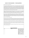
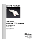
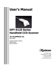
1
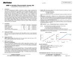
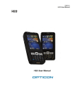
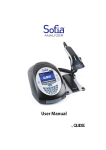
Users Manual Series NLB 9625/9645 Fixed Position Laser Bar Code Scanner Manual No. 25-NLB0045-01 Rev. October 1999 8 Olympic Drive Orangeburg, NY 10962 Tel 845.365.0090 Fax 845.365.1251 www.opticonUSA.com * This page left intentionally blank for repagenation * Contents Section 1 Introduction and Getting Started ..................................... 1 Product Overview ............................................................................. 1 Quick Start-Up Procedure .................................................................. 1 Section 2 Technical Specifications ................................................... 3 Physical Specifications ....................................................................... 3 Optical Specifications ........................................................................ 3 Electrical Specifications ..................................................................... 4 RS232 Communications Specifications ................................................ 5 Environmental Specifications ............................................................. 5 Section 3 Positioning the Scanner ................................................... 7 Getting Optimum Performance ........................................................... 7 Measuring Scanner Performance ...................................................... 10 Application Notes ............................................................................ 11 Section 4 Configuring The Scanner ................................................ 13 Programming Menus & Commands ................................................... 13 Programming via Bar Codes ............................................................. 13 Programming via Computer Commands ............................................ 14 Factory Default Settings .................................................................. 15 Section 5 Application Engineering Support .................................... 17 Technical Assistance and Support ..................................................... 17 Common Causes of Poor Performance .............................................. 17 Modified and/or Customized Scanners .............................................. 17 Section 6 Scanner Labeling ............................................................ 19 CDRH Class II ................................................................................ 19 Appendix A Programming Menus & Commands ............................. 21 Appendix B Dimensional Drawings ................................................ 53 Appendix C Optical Charts .............................................................. 55 * This page left intentionally blank for repagenation * Organization of this Manual This manual provides the necessary instructions for installing and using an Opticon NLB 9625/9645 Series Fixed Position Laser Scanner. The manual is organized as follows: Section 1 Section 2 Section 3 Section 4 Section 5 Introduction and Getting Started Describes the general operation of the NLB 9625/9645 Series scanner. Also provides a Quick Start-Up Procedure that allows you to begin using the scanner immediately. Technical Specifications Provides complete specifications, including mechanical details, optical performance, RS232 communications and other technical data. Positioning Scanner for Optimum Performance Provides detailed instructions and tips for mounting and positioning the scanning to obtain the best scanning performance. Application Notes describe guidelines for maximizing specific characteristics. Configuring Your Scanner Describes how various parameters can be programmed to customize the scanner for your specific application. Application Engineering Support Discusses the most common questions and concerns when adapting the NLB 9625/9645 Series scanner in your application. Appendices Detailed Supporting Information Provides detailed information in specific areas such as the programming commands for configuring various parameters of the NLB 9625/9645 Series scanner. * This page left intentionally blank for repagenation * Manual No. 25-NLB0045-01 Series NLB-9625/9645 Mini Laser Fixed Position Scanner Section 1 Introduction and Getting Started Product Overview The NLB-9625/9645 Series Fixed Position Scanners are miniature, 33 or 200 scans per second, laser bar code readers designed to be easily incorporated into host equipment. Utilizing a solid state laser diode and a brushless motor results in a minimum of wear on parts and high performance. The scanner is encased in a rugged steel enclosure to assure durability and reliability. Advanced 16-bit microprocessor technology coupled with Opticons proven decoding algorithms result in superior accuracy. The scanners are fully programmable allowing the user to customize parameters including changing communication settings, selecting symbologies, adding prefixes and appending suffixes. Programmable settings can be downloaded from the host CPU or computer directly to the scanner. NLB 9625/9645 Series laser scanners are encased in compact, rugged steel enclosures. The compact size permits installation in the tightest areas. Scanners are available in both front and side view configurations allowing great flexibility in mounting and positioning the scanner for optimum performance. Quick Start-Up Procedure This section is for those who wish to start using the scanner before reading the complete manual. In only a few steps the scanner will be operable. 1) Turn off the power to your PC and connect the scanner to an RS232 communications port. Note: You must provide +5 Volt DC power to the scanner. This can be accomplished using the power supply and patch cable available from Opticon. Turn on the power to the PC. 2) Using communications software (e.g., Procom), set the communication parameters: 9600 baud, 1 Start / Stop Bit, 8 Data Bits, No Parity, No Handshaking, No Flow Control. 3) If you are operating in a Microsoft Windows 3.1 environment, skip to Step 5. 4) If you are operating in a Microsoft Windows 95 environment, you can set the communication parameters using Hyper Terminal as follows: ♦ ♦ ♦ ♦ ♦ ♦ Open Hyper Terminal. This can be done from Start→Programs→Accessories Select Hypertrm.exe to create a New Connection. In the Connection Description dialog screen enter a name for the new file. If desired, select an Icon. Click OK. In the Phone Number dialog screen, in the box entitled: Connect using. select the communication port, for example, Direct to Com 1. Click OK. In the Com 1 Properties screen, enter the appropriate Port Settings: Bits per second = 9600 Data bits = 8 Parity = None Stop Character = 1 Handshaking = None Click OK. The HyperTerminal folder you just created will open. From the File pull-down menu, select Properties, then click on the Setting Tab. Page 1 Manual No. 25-NLB0045-01 Series NLB-9625/9645 Mini Laser Fixed Position Scanner ♦ In the Properties Settings dialog screen: ♦ Select Terminal keys for the Function, arrow and control key Select ANSI for Emulation, The Backscroll buffer line can remain at the default 500 Click on the ASCII Setup button. In the ASCII Setup screen, select Echo typed locally so that any keyboard commands you input will appear on your screen. Click OK. This returns you to the Properties Setting. Click OK. Your PC and the scanner should now communicate. Skip to Step 6. 5) In a Microsoft Windows 3.1 environment, set the communication parameters using the Terminal function of Windows. ♦ ♦ ♦ ♦ ♦ ♦ ♦ From Windows Program Manager Main Menu, select Terminal From the Terminal menu, select Settings From the Settings menu, select Terminal Emulation Set the emulation to TTY (generic) From the Settings menu, select Terminal Preferences and select the following: Terminal Modes: Line Wrap / Local Echo / Sound CR /LF: Inbound, Outbound Columns: 80 From the Settings menu, select Communications. Select the COM port and set communication parameters as shown in Step 2, including no flow control. 6) To verify that the scanner and the PC are communicating properly, send the following command from your PC keyboard to activate the scanners buzzer. Send the command: <Escape> V5 <Carriage Return> Note: Be sure to use capital letters (e.g. V5, not v5). The buzzer should sound, indicating that good communications have been established. 7) A red laser light should be visible. Do not stare into the laser light. If the light is not visible, the scanner may be waiting for a Trigger Command from the host to activate it. Send the following computer command to place the scanner into the Triggered Disabled mode: <ESC> S7 <CR> In this Triggered Disabled mode, the red laser light is always illuminated. You are now ready to scan barcodes. 8) Position the red laser light of the scanner over the bar code symbol to be read. When the bar code symbol is decoded, the scanner will beep and transmit the data to the screen of your PC. You may have to move the scanner closer or farther away from the bar code symbol in order to locate the best distance for reading. This Quick Start-Up procedure will get you started reading bar code symbols. However, in order to best understand the full capabilities of this scanner, you should read the complete manual. Page 2 Manual No. 25-NLB0045-01 Series NLB-9625/9645 Mini Laser Fixed Position Scanner Section 2 Technical Specifications Physical Specifications Case Material Weight Cable Length Mounting Steel, painted dark gray 7.7 ounces (220 grams) without cable 6-ft (2.8m) with DB25 pin female connector 6 threaded (M-3) mounting holes. (screws should not extend more than 5 mm into case) Dimensions (LxWxH) 9627/9647 Front View2.9 x 2.7 x 1.0 in (74 x 68 x 26 mm) 9626/9646 Side View4.3 x 2.7 x 1.2 in (110 x 68 x 30 mm) Symbologies Supported Codabar Code 39 Code 93 Code 128 Standard 2 of 5 Interleaved 2 of 5 MSI / Plessey UPC / EAN / JAN Optical Specifications Scan Rate 9626/9627 33 scans per second 9646/9647 200 scans per second Light Source Solid state laser diode (670 nm) Light Beam Distribution Rotating polygon Read Sensor 2048 pixel CCD linear array Focal Distance (nominal) from window 9627 Front View 5.6 inches 9647 Front View 5.2 inches 9626 Side View 3.5 inches 9646 Side View 4.2 inches Min. Bar Code Curvature (Radius) 0.6 inches for 10.4 mil EAN-8 label 0.8 inches for 10.4 mil EAN-13 label Page 3 Manual No. 25-NLB0045-01 Series NLB-9625/9645 Mini Laser Fixed Position Scanner Electrical Specifications Operating Voltage +5VDC + 10% Current Consumption Dynamic Static Surge 170 mA typical / 200 mA max. 20 mA max. 2.5 A for 37.5µS (1.0A/15µS) 2.5 A for 37.5µs 200 mA Motor/Laser Surge 50 mS 170 mA Dynamic Current Current / / Trigger Timeout Power On Delay 450 mS (min) / / 20 mA Static Current Trigger On Time Connector Pin-outs DB25 pin Female connector with screws. Pin No. 1 2 3 4 5 7 16 25 Page 4 Signal Frame Ground RXD TXD CTS RTS Signal Ground Trigger +5V Color Black White Green Blue Gray Purple Brown Red Manual No. 25-NLB0045-01 Series NLB-9625/9645 Mini Laser Fixed Position Scanner RS232 Communications Specifications Parameter Timing No. of Start Bits No. of Stop Bits No of Data Bits Parity Baud Rate Handshaking Default Asynchronous 1 bit 1 bit 8 bit None 9600 baud None Optional Settings 1 or 2 bits 7 or 8 bits Odd / Even / None 150 to 19200 baud Hardware / Software/ None RS232 Transmit / Receive Character Format TXD/ RXD Start Bit Bit LSB 7 or 8 Data Bits MSB Parity Bit Stop Bit RS232 Data Format Transmit Receive Decoded Data ESC Command CR CR RS232 Signal Level Signal Name In / Out TXD RXD Out In RS232C Level Mark/Off Space/On -5 to -15 +5 to +15 -3 to 15 +3 to +15 Environmental Specifications Temperature Operating Storage -10 to +40° C (14 to 104° F) -30 to +60° C (-22 to 140° F) Humidity (non-condensing) Operating 5% to 95% Storage 5% to 95% CDRH Class II This product conforms to 21 CFR 1040.1 and 21 CFR 1040.11 Page 5 Manual No. 25-NLB0045-01 Series NLB-9625/9645 Mini Laser Fixed Position Scanner * This page left intentionally blank for repagenation * Page 6 Manual No. 25-NLB0045-01 Series NLB-9625/9645 Mini Laser Fixed Position Scanner Section 3 Positioning the Scanner Getting Optimum Performance Three items greatly impact scanner performance: 1) Distance from the scan window to the bar code 2) Specular Reflection 3) Quality of bar code labels 1) Distance to the Bar Code The operation of the scanner is similar to a camera. If you photograph an object that is out of focus, the resulting picture will be blurry. The same is true with the scanner. If the bar code label is out of focus, the scanner may have difficulty decoding what appears to be fuzzy bars and spaces. Focal Distance Ideally, the distance from the window of the scanner to the bar code label should be equal to the focal distance of the scanner. For the NLB-9625/9645 Series fixed position laser scanners, the nominal focal distances are: 9626 9627 9646 9647 Side View3.5 in (88.9 mm) Front View5.6 in (142.3 mm) Side View 4.2 in (107 mm) Front View 5.2 in (132 mm) Page 7 Manual No. 25-NLB0045-01 Series NLB-9625/9645 Mini Laser Fixed Position Scanner Depth-of-Field Just as with a camera, the scanner has a depth-of-field. It can read bar codes that are not precisely at the focal distance maybe a little closer, or a little farther away. However, if the bar code label is positioned too far from the focal distance, the scanner may not be able to successfully decode it. The depth-of-field varies based on the density of the bar code, i.e., the thickness of the bars. Very high density bar codes (which have very narrow bars) are readable over a much shorter distance range than low density bar codes with larger bars. The following table shows the typical depth-of-field (closest to farthest reading distances) for the NLB9625/9645 Series scanners. The actual performance may differ slightly from unit to unit. Also, it is important to note that this data was measured under ideal conditions using high quality bar code labels. In a real world environment the conditions will not be as ideal. Therefore, the best practice is to position the scanner at its focal distance rather than at the extremes of its depth-of-field. Typical Reading Distance from Window (Depth-of-Field) Bar Code Density 13.0 mil 10.0 mil 7.5 mil 9626 Side View 9627 Front View 9646 Side View 9647 Front View Min. Max. Min. Max. Min. Max. Min. Max. 0.0 0.5 1.8 7.0 6.0 5.4 1.1 2.4 3.4 8.0 7.4 6.5 0.5 1.9 2.2 7.5 6.5 5.6 2.0 3.5 3.8 9.5 7.0 6.5 Readable Bar Code Width (Field-of-View) The following table shows the field-of-view at various distances from the window. The field-of-view is the max. width that the scanner is capable of reading. A bar code label positioned anywhere within this field-ofview can be decoded. The field-of-view is also a measure of the widest bar code label that can be read. Remember, the width of a bar code label includes not only the bars and spaces but also the required white space (quiet zone) on each end. Field-of-View (Maximum Readable Bar Code Width) Distance 9627 9647 9626 from Window Front View Front View Side View 2 inches 2.6 2.6 3.8 3 inches 3.3 3.3 4.8 4 inches 4.3 4.3 5.7 5 inches 5.1 5.1 6.6 6 inches 5.9 5.9 7.8 7 inches 6.8 6.8 N/A 9646 Side View 3.8 4.8 5.7 6.6 7.8 N/A Good design policy is to position the scanner at its focal distance and at the center of the field-of-view. Do not position it near the extremes of the reading range. Page 8 Manual No. 25-NLB0045-01 Series NLB-9625/9645 Mini Laser Fixed Position Scanner 2) Avoiding Specular Reflection Do not position the scanner at an angle that causes the laser scan line to be reflected directly back into the scanner. This is called specular reflection. Too much reflected light can blind the scanner preventing a good decode. If the bar code label is located on a flat surface, specular reflectivity occurs between +3 degrees off perpendicular (See diagram in Section 2). If the bar code label is located on a cylindrical surface, such as a test tube, the angle of specular reflection is measured tangent to the curve. If the curved surface is also moving, there may be more than one position causing specular reflection. Bar Code Avoid +3° Region Scan Line NLB-964x NLB-964x Specular Reflection Area: Avoid +3° around X axis (see diagram above). Preferred angle is +10° Skew Z Axis Skew Angle Rotation Tilt Angle +60° around Y axis +60° around Z axis +55°, -50° around X axis Page 9 Manual No. 25-NLB0045-01 Series NLB-9625/9645 Mini Laser Fixed Position Scanner 3) Quality of Bar Code Labels The quality of the bar code label can affect the scanning performance. Poor quality labels are more difficult to decode and may result in non-reads or potential misreads. The bar code label should be printed to specifications. This means that the bars are printed within spec, with the correct widths, no ink spread, crisps edges and no voids. There should be a sufficient quiet zone on both end of the bar code label. For best results the paper or label stock should have a matte finish to diffuse light. The print contrast signal (which is a comparison of the reflectance of the bars and the background stock) should be as high as practical. Measuring Scanner Performance Two methods are helpful in determining the optimum position of the scanner. The first method is to program the scanner for Trigger Disable and Continuous Read modes. The scanner will be ON continuously and will continuously read the same bar code. Since the buzzer sounds each time the bar code is read, the sound of the buzzer can be used like a Geiger counter. As the position of the scanner changes the sound of the buzzer will change. The buzzer sound will be loudest and most continuous at the best reading positions. The Read Rate Test The second method, the Read Rate Test, provides a mathematical calculation of scanning performance. In this test the scanner scans a bar code 100 times and then calculates the number of those scans that resulted in a good decode. That number, expressed as a percentage, will be transmitted to the host. For example, 93% means that the scanner decoded the bar code symbol 93 times out of the 100 scan attempts. By performing the Read Rate Test with the scanner mounted in various positions you can determine which of those locations results in the best performance. Heres how to perform the Read Rate Test: 1) Program the scanner for Continuous Read (S2) and Trigger Enabled (S8). 2) Instruct the scanner to enter the Read Rate Test mode (ZA). 3) Locate the scanner in the desired position relative to a test bar code then enter a Z command. The scanner will read the bar code once and store it in memory. 4) Enter another Z command. The scanner will scan the bar code 100 times and then transmit the Read Rate Percentage to the host. 5) Steps 3 and 4 can be repeated as often as desired, moving the scanner to new locations before each test. 6) Exit the Read Rate Test mode (ZG). Page 10 Manual No. 25-NLB0045-01 Series NLB-9625/9645 Mini Laser Fixed Position Scanner Application Notes Tips for Achieving High Throughput In some applications your primary objective may be to achieve the highest possible throughput rate. The following list identifies the parameters and scanner settings that can maximize scanning and decode throughput speed. Note, by emphasizing max. throughput, other areas of performance may be affected. For example, the number of non-reads could increase. If high throughput is critical, consider some or all of these settings. ♦ ♦ ♦ ♦ ♦ ♦ ♦ Operate in the Trigger Disabled mode. Operation of the trigger can require as much as 200 msec before decoding begins, slowing down throughput rate. Only enable those symbologies that you will be decoding. Eliminate all suffixes and prefixes. Minimize the number of redundant reads required before transmitting data. Transmit the decoded data at the highest baud rate, 19200 baud. Disable both the hardware and software buzzer functions. If you need a buzzer, use the hardware buzzer rather than the software buzzer. Tips for Insuring Highest Data Integrity There are several parameters that can enhance your confidence that the correct bar code data is transmitted. Note that by emphasizing the accuracy and security of the data other areas of the scanner operation may be affected, for example, you may not achieve the highest throughput. If accuracy and data integrity are critical, consider some or all of these settings. ♦ ♦ ♦ ♦ ♦ ♦ ♦ ♦ Program the scanner to require a high number of redundant decodes prior to transmitting. For example, program the scanner to decode a bar code exactly the same way three consecutive times before transmitting the data. Then decoding the bar code the same way 2 out of 3 times or any 3 out of 4 times is not sufficient. It must obtain three consecutive and identical decodes. Utilize a predetermined, fixed-length of bar code. Program the scanner to only decode a bar code of that length. Bar codes of any other length will be ignored. The quality of the printed bar code must be excellent. Use a bar code symbology that contains an internal check digit and program the scanner to calculate that check digit for validity prior to transmitting. Do not use a symbology with poor internal verification, or subject to partial decodes, such as 2 of 5 or MSI/Plessey. Only enable those symbologies that you will be decoding. Transmit data at low baud rates to minimize communication errors. Enable the Number of Characters Transmitted. The scanner will calculate and transmit a number indicating the total number of characters it is transmitting. Your host application program can compare this number with the actual number of characters received to verify that the correct amount of data is received. Page 11 Manual No. 25-NLB0045-01 Series NLB-9625/9645 Mini Laser Fixed Position Scanner Tips for Verifying the Presence of a Bar Code If the scanner is operated in the trigger enabled mode and the trigger is activated, one of three conditions may occur: Decoded data is A bar code is scanned and decoded transmitted A bar code is scanned but is not No data is transmitted decoded (e.g., print quality was poor) No data is transmitted No bar code is present In some applications, when no data is transmitted, it may be important to know why. Was there a bar code present that could not be decoded, or was no bar code present at all? This requirement is common in applications such as automated blood analysis equipment. Test tubes containing blood samples from many different people are loaded into a rack for automatic analysis. The bar code on each tube ties that sample and the results back to a specific individual. If no bar code data is transmitted it is critical to understand the reason. Your Opticon scanner, when operated in the Trigger Enabled mode, can be programmed to transmit an error message that indicates whether or not a bar code was present. The following table shows the message that will be transmitted for each condition. Presence/Absence of Bar Code Bar code was present and correctly decoded No bar code was present Bar code was present but could not be decoded Page 12 Scanner Transmits Decoded Data <STX> ? <ETX> <STX> > <ETX> Manual No. 25-NLB0045-01 Series NLB-9625/9645 Mini Laser Fixed Position Scanner Section 4 Configuring The Scanner Since operation of the NLB 9625/9645 Series laser scanner is microprocessor controlled, it is possible to modify or program its operation to match your specific application. Changes in parameter settings can be changed or programmed in two ways. The first method employs specially designed programming bar codes, which instruct the scanner to modify specific parameters. The second is that the scanner can also be programmed by sending software instructions from the host PC to the scanner via the RS232 connection. Programming Menus & Commands Two different methods can be used to program parameters to configure the scanner: a. Programming via Bar Codes from a menu page; or b. Programming via Computer Commands Most parameters can be programmed using either of these two methods. However, there are certain parameters that are only programmable via the bar code menu. Programming via Bar Codes Use the following steps to program parameters via the bar code menu: 1) Scan the START bar code. This instructs the scanner to enter the Programming Mode. While in this mode the scanner will beep intermittently. 2) Scan the bar code(s) associated with the desired parameter(s). The scanner will beep when the bar code is scanned. Note: Because of the close proximity of bar codes on the menu, approaching the desired bar codes from the side of the page will ensure that the only correct bar code is scanned. 3) Scan the STOP bar code. This instructs the scanner to exit the Programming Mode. All the parameters that are programmed via bar codes are retained in non-volatile memory and stored permanently (even if the scanner is powered down) or until they are changed again. Page 13 Manual No. 25-NLB0045-01 Series NLB-9625/9645 Mini Laser Fixed Position Scanner Programming via Computer Commands Various parameters can be programmed by sending software commands or keyboard strokes from the host computer to the scanner in the following format: <ESC> Computer Command <CR> Note: 1) Only upper case letters are recognized, e.g. AB , not ab 2) Each Command normally consists of two characters 3) Downloading of software commands cannot be grouped together. Each command must be preceded by <ESC> and followed by a <CR> Parameters changed by downloading software commands remain in effect only while power is supplied to the scanner. If power is interrupted or terminated, the parameters return to their original settings. However, parameters programmed by downloaded commands can be stored permanently by transmitting a Z2 Computer Command to the scanner after the commands are sent. This instructs the scanner to store the changed parameter in non-volatile memory. The scanner will then retain the setting permanently or until it is changed. It is not necessary to send a Z2 command after each parameter is changed. One Z2 command will save all changes. If you want to program the scanner so that it will only decode a Code 128 bar code, you would send the following command: <ESC> A6 <CR> The scanner will now only decode Code 128 bar codes. It will ignore any other type of bar code. The scanner will retain this setting until power is shut off. Then it will revert to its original setting. If you want to retain this setting permanently, you would send the following commands: <ESC> A6 <CR> then <ESC> Z2 <CR> The Z2 command stores the changed parameter in non-volatile memory. The scanner will now retain that setting even after power is terminated. Appendix A contains full instructions on how to configure the scanner as well as a complete listing of the computer commands and programming bar codes that are available to customize the scanner for your application. Page 14 Manual No. 25-NLB0045-01 Series NLB-9625/9645 Mini Laser Fixed Position Scanner Factory Default Settings Factory default settings are indicated by the word (Default) throughout the Programming menus located in Appendix A. When you modify or change any parameters, the scanner can be programmed to retain the new parameter in memory, even if power interrupted or terminated. If for any reason, however, the scanner is instructed to return all parameters to default settings, it will return to the factory default settings shown in the following table. Parameter RS 232 Communications Trigger Function Read Mode No. of Redundant Decodes Bar Code Symbologies UPC-A (13 digits) UPC-E (7 digits) Code 39 Codabar 2 of 5 Fixed length of bar code only Software buzzer Positive bar codes only Error indications Print quality adjustment Factory Default Setting 9600 baud 8 data bits 1 stop bit No parity No handshaking Disabled Multiple Read Mode Two All Symbologies enabled Add leading zero Enable check digit Add leading zero Enable check digit Do not calculate check digit Enable start/stop characters (*.....*) Disable character length of one Enable start/stop characters as abcd/abcd Do not calculate check digit Disable character length of one Do not calculate check digit Disable characters length of two Disabled Disabled Enabled Do not transmit error code Output from Low or High analog gain 1 MHz sampling rate Page 15 Manual No. 25-NLB0045-01 Series NLB-9625/9645 Mini Laser Fixed Position Scanner * This page left intentionally blank for repagenation * Page 16 Manual No. 25-NLB0045-01 Series NLB-9625/9645 Mini Laser Fixed Position Scanner Section 5 Application Engineering Support Technical Assistance and Support Opticon is eager to help you integrate the NLB 9625/9645 Series laser scanner into your application. We have a proven track record of successful applications. Our technical support staff is available to answer any questions or work with you to adapt the scanner to your specific situation. We are happy to answer your questions, assist in configuring and positioning the scanner for optimum operation, and help resolve any problems you encounter. Call us at 1 (800) 636-0090. Common Causes of Poor Performance The most common reasons for poor scanning performance are listed below. ♦ Bar codes are not positioned at the focal distance of the scanner. ♦ Specular reflection is impacting the scanner. Change the angle/position of the scanner or the bar code. ♦ Poor quality of printed bar codes. Bar codes are out of specification. ♦ The paper on which the bar code is printed is highly reflective or has a glossy finish causing light to be reflected into the scanner. ♦ The distance from the scanner to the bar code is not suitable for the density of the bar code. Or the density of the bar code beyond the scanners capability. ♦ If the red illuminating light of the scanner is not on, the scanner may be in the Trigger Enable mode expecting a trigger signal. Modified and/or Customized Scanners Opticon will work with you to modify or customize scanners to match your requirements. Scanners can be modified in terms of connectors type, pin-outs, cable length, default settings, custom software and many other areas. Opticon will modify scanners in our factory and ship you scanners that match your specific requirements. By incorporating your modifications directly into production scanners, you receive scanners tailored for your need. They can be used immediately without the need for further modification or rework. Page 17 Manual No. 25-NLB0045-01 Series NLB-9625/9645 Mini Laser Fixed Position Scanner * This page left intentionally blank for repagenation * Page 18 Manual No. 25-NLB0045-01 Series NLB-9625/9645 Mini Laser Fixed Position Scanner Section 6 Scanner Labeling CDRH Class II The NLB 9625/9645 Series scanner complies with Center for Devices and Radiological Health (CDRH) regulation 21, CFR Subchapter J. A NLB 9625/9645 Series scanner uses a low-power, visible laser. As with any very bright light source, such as the sun, the user should light beam. Momentary exposure to a CDRH Class II laser is not known to be harmful. C A U T IO N LASER PRECAUTION: DO NOT STARE INTO BEAM ID/ Certification Label Laser Caution Label Required safety label as it appears on the scanner. Note: Do not open the scanner. The scanner contains no user adjustable or serviceable parts in the interior of the scanner. All product service must be performed by the Opticon Service Department in Orangeburg, NY. Opening the scanner will void the warranty and could expose you to laser energy. Laser diode power of up to 2 mWatt average could be accessible in the interior of the scanner. If a NLB 9625/9645 Series scanner is incorporated or interfaced to other equipment, that equipment should include an indicator that is illuminated whenever laser energy is being emitted from the scanner. This indicator may remain illuminated when the scanner is powered but the laser is not emitting energy. CAUTION: Use of controls, adjustments or performance of procedures others than those specified herein may result in hazardous visible light exposure. Page 19 Manual No. 25-NLB0045-01 Series NLB-9625/9645 Mini Laser Fixed Position Scanner * This page left intentionally blank for repagenation * Page 20 Manual No. 25-NLB0045-01 Series NLB-9625/9645 Mini Laser Fixed Position Scanner Appendix A Programming Menus & Commands Index Introduction ................................................................................... 22 Programming via Bar Codes ............................................................. 22 Programming via Computer Commands ............................................ 22 Global Default & Scanner Configuration ............................................ 24 Symbology Selections ..................................................................... 25 Adding/Activating Specific Symbologies ............................................ 26 Options for UPC .............................................................................. 27 Options for Code 39 ........................................................................ 28 Options for Codabar ........................................................................ 29 Options for 2 of 5 ........................................................................... 30 Fixing the Number of Digits ............................................................. 31 Creating a Prefix and/or Suffix ......................................................... 32 Setting Prefixes (Identifying the Symbology) ..................................... 32 Setting Suffixes (Identifying the Symbology) ..................................... 34 Direct Input of Numeric Characters .................................................. 36 Direct Input of Alpha Characters ...................................................... 37 Direct Input of Control Characters .................................................... 38 Enable Number of Characters/Digits Transmitted ............................ 39 Disable Number of Characters/Digits Transmitted ........................... 41 Baud Rate Settings ......................................................................... 43 Communication Parameters ............................................................. 44 Handshaking .................................................................................. 45 Buzzer Operation ............................................................................ 46 Positive & Negative Bar Codes ......................................................... 47 Setting the Trigger Function ............................................................ 47 Selecting the Read Mode ................................................................. 48 Scanner Timeout (Trigger Enable Mode only) .................................... 49 Number of Redundant Decodes ....................................................... 50 Transmitting Error Indications (Trigger Enabled only) ......................... 51 Print Quality Adjustments ................................................................ 52 Page 21 Manual No. 25-NLB0045-01 Series NLB-9625/9645 Mini Laser Fixed Position Scanner Introduction Two different methods can be used to program parameters to configure the scanner: a) Programming via bar codes from a menu page; or b) Programming via computer commands Programming via Bar Codes Use the following steps to program parameters via the bar code menu: 1) Scan the START/END Programming Menu bar code. This instructs the scanner to enter the Programming Mode. The scanner will beep intermittently while in this mode. 2) Scan the bar code(s) associated with the desire parameter(s). The scanner will beep when the bar code is scanned. Note: Because of the close proximity of bar codes on the menu, approaching the desired bar codes from the side of the page will ensure that only the desired bar code is scanned. 3) Scan the START/END Programming Menu bar code. This instructs the scanner to exit the Programming Mode. All the parameters that are programmed via bar codes are retained in non-volatile memory and stored permanently (even if the scanner is powered down) or until they are changed. Programming via Computer Commands Various parameters can be programmed by sending software commands or keyboard strokes from the host computer to the scanner in the following format: <ESC> Computer Command <CR> Note: Only upper case letters are recognized, e.g. AB, not ab. Each command typically consists of two characters. Downloading of software commands cannot be grouped together. Each command must be preceded by <ESC> (Escape) and followed by <CR> (Carriage Return). B). Factory default settings are indicated throughout the following menus by the pointing hand icon ( NOTE: Where computer commands appear in parenthesis, bar code commands must be used to program the scanner. Page 22 Manual No. 25-NLB0045-01 Series NLB-9625/9645 Mini Laser Fixed Position Scanner Parameters modified by downloading software commands remain in effect only while power is supplied to the scanner. If power is interrupted or terminated, the parameters return to their original settings. However, parameters programmed by downloaded commands can be stored permanently by transmitting a Z2 computer command to the scanner after the commands are sent. this instructs the scanner to store the changed parameter(s) in non-volatile memory. The scanner will then retain the setting(s) permanently or until changed. It is not necessary to send a Z2 command after each parameter is changed. One Z2 command will save all changes. Example: If programming the scanner to decode only Code 128 bar code were desired, the following command would be used: <ESC> A6 <CR> The scanner will now only decode Code 128 bar codes and will ignore other types of bar code. The scanner will retain this setting until power is interrupted or terminated, and will then revert to its original setting. If retaining this setting permanently is desired, the following command would be used: <ESC> A6 <CR> <ESC> Z2 <CR> The Z2 command stores the modified parameter in non-volatile memory. The scanner will not retain this setting even after power is terminated. Page 23 Manual No. 25-NLB0045-01 Series NLB-9625/9645 Mini Laser Fixed Position Scanner Global Defaults & Scanner Configuration Page 24 Computer Command Function /Description Bar Code Command (Z7) START/END Programming Menu ,Z7, U4 Return all parameters to Default Settings 1Y Clear all prefixes ,1Y, 1Z Clear all suffixes ,1Z, Z3 Display software settings and version number ,Z3, Z4 Display prefix/suffix value length (expressed in hexadecimal format) ,Z4, ,U4, B Manual No. 25-NLB0045-01 Series NLB-9625/9645 Mini Laser Fixed Position Scanner Symbology Selection Computer Command Function /Description Bar Code Command (Z7) START/END Programming Menu ,Z7, A0 Read all symbologies ,A0, J1 UPC Only ,J1, J2 UPC +2 Only ,J2, J3 UPC +5 Only ,J3, J4 EAN Only ,J4, J5 EAN +2 Only ,J5, J6 EAN +5 Only ,J6, A2 Code 39 Only ,A2, A3 Codabar Only ,A3, J7 Standard 2 of 5 Only ,J7, J8 Interleaved 2 of 5 Only ,J8, A5 Code 93 Only ,A5, A6 Code 128 Only ,A6, A7 MSI/Plessey Only ,A7, Page 25 Manual No. 25-NLB0045-01 Series NLB-9625/9645 Mini Laser Fixed Position Scanner Adding/Activating Specific Symbologies Page 26 Computer Command Function /Description Bar Code Command (Z7) START/END Programming Menu ,Z7, B2 Enable Code 39 ,B2, B3 Enable Codabar ,B3, R7 Enable Standard 2 of 5 ,R7, R8 Enable Interleaved 2 of 5 ,R8, B5 Enable Code 93 ,B5, B6 Enable Code 128 ,B6, B7 Enable MSI/Plessey ,B7, R1 Enable UPC ,R1, R2 Enable UPC +2 ,R2, R3 Enable UPC +5 ,R3, R4 Enable EAN ,R4, R5 Enable EAN +2 ,R5, R6 Enable EAN +5 ,R6, Manual No. 25-NLB0045-01 Series NLB-9625/9645 Mini Laser Fixed Position Scanner Options for UPC Computer Command Function /Description Bar Code Command (Z7) START/END Programming Menu ,Z7, E2 UPC-A (13 Digits) Add leading zero Enable Check Digit ,E2, B E3 UPC-A (12 Digits) Do not add leading zero Enable Check Digit ,E3, E4 UPC-A (12 Digits) Add leading zero Enable Check Digit ,E4, E5 UPC-A (11 Digits) Do not add leading zero Disable Check Digit ,E5, E6 UPC-E (8 Digits) Add leading zero Enable Check Digit ,E6, E7 UPC-E (7 Digits) Do not add leading zero Enable Check Digit E8 UPC-E (7 Digits) Add leading zero Disable Check Digit ,E8, E9 UPC-A (6 Digits) Do not add leading zero Disable Check Digit ,E9, ,E7, B Page 27 Manual No. 25-NLB0045-01 Series NLB-9625/9645 Mini Laser Fixed Position Scanner Options for Code 39 Computer Command Function /Description Bar Code Command (Z7) START/END Programming Menu ,Z7, C0 Do not calculate Check Digit C1 Calculate Check Digit ,C1, C2 Transmit Check Digit ,C2, C3 Do not transmit Check Digit ,C3, D0 Disable start/stop characters (*.......*) ,D0, D1 Enable start/stop characters (*.......*) ,D1, B ,C0, B ♦ 43 Data digits are available: 0 to 9, A to Z (caps only) plus . - $ / + % and space. If a check digit is present, it will appear as part of the data. ♦ If the scanner is programmed to calculate the check digit, and the bar code is not printed with a check digit, the bar code will not read. ♦ Another option available for Code 39 is to enable the reading of a single character bar code. See the section on Fixing the Digit for this option. Page 28 Manual No. 25-NLB0045-01 Series NLB-9625/9645 Mini Laser Fixed Position Scanner Options for Codabar Computer Command Function /Description Bar Code Command (Z7) START/END Programming Menu ,Z7, F0 Disable start/stop characters ,F0, F1 Enable start/stop characters as ABCD/TN*E ,F1, F2 Enable start/stop characters as abcd/tn*e ,F2, F3 Enable start/stop characters as ABCD/ABCD ,F3, F4 Enable start/stop characters as abcd/abcd F5 Transmit Check Digit ,F5, F6 Do not transmit Check Digit ,F6, F7 Do not calculate Check Digit ,F7, B F8 Calculate Check Digit (Modulo 10) ,F8, F9 Calculate Check Digit (Modulo 16) ,F9, ,F4, B Codabar Format Start Character 1 to 42 Data Digits Check Digit Stop Character A.... ....T a.... ....t A.... ....A a.... ....a Codabar has four different start/stop character schemes as shown. The check digit is optional and, if present, would be the last character. ♦ If the scanner is programmed to calculate the check digit, and the bar code is not printed with a check digit, the bar code will not be read Page 29 Manual No. 25-NLB0045-01 Series NLB-9625/9645 Mini Laser Fixed Position Scanner Options for 2 of 5 Computer Command Function /Description Bar Code Command (Z7) START/END Programming Menu ,Z7, G0 Do not calculate Check Digit G1 Calculate Check Digit ,G1, G2 Transmit Check Digit ,G2, G3 Do not transmit Check Digit ,G3, ,G0, B 2 of 5 Format (Standard & Interleaved) 1 to 44 Data Digits numbers only (0 to 9) Check Digit Check Digit Opticon recommends strongly that the Fixing the Number of Digits feature on the next page be employed whenever 2 of 5 bar codes are used. Page 30 Manual No. 25-NLB0045-01 Series NLB-9625/9645 Mini Laser Fixed Position Scanner Fixing the Number of Digits Computer Command Function /Description Bar Code Command (Z7) START/END Programming Menu ,Z7, H0 Disable Fixation ,H0, B H1 Enable Fixation ,H1, H2 Disable 1 character Code 39 Disable 1 character Codabar Disable 2 character 2 of 5 H3 Enable 1 character Code 39 Enable 1 character Codabar Enable 2 character 2 of 5 ,H2, B ,H3, To avoid truncation errors, the scanner can be programmed to only decode bar codes of one specific length, i.e., containing a specific number of digits. It is also possible to program the scanner to only decode bar codes of either of two specific lengths. To fix one (1) length (or number of digits) of bar code: To fix two (2) different lengths of bar codes: 1. Scan START to enter programming mode 2. Scan Enable fixation bar code 3. Scan a sample bar code of desired length 4. Repeat Step #3, re-scanning the sample bar code 5. Scan STOP to exit programming mode 1. Scan START to enter programming mode 2. Scan Enable fixation bar code 3. Scan a sample bar code of desired length #1 4. Scan a sample bar code of desired length #2 5. Scan STOP to exit programming mode Fixing the Number of Digits can only be applied to Code 39, Codabar, 2 or 5 and MSI/Plessey (UPC, Code 93 and Code 128 are not affected). Page 31 Manual No. 25-NLB0045-01 Series NLB-9625/9645 Mini Laser Fixed Position Scanner Creating a Prefix and/or Suffix The scanner can be programmed to transmit a prefix and/or suffix with the decoded data. A Prefix (or a Suffix) is composed of up to 4 characters. The following steps are used to establish a Prefix that will be transmitted with the bar code data: 1. Scan START to enter the Programming Mode. 2. Scan the bar code representing the symbology to which you wish to add a Prefix. 3. Scan the character(s) that will comprise the Prefix. Up to 4 numeric, alpha or control character(s) may be used. 4. Scan STOP to exit the Programming Mode. The same steps are used to establish a Suffix. Example: To add the alpha character A as a Prefix and B as a Suffix to UPC-A bar code data: 1) 2) 3) 4) 5) 6) Scan START/END Programming Mode Scan N1, representing a Prefix for UPC-A Scan 0A, representing the alpha character A Scan N6, representing a Suffix for UPC-A Scan 0B, representing the alpha character B Scan START/END Programming Mode Setting Prefixes (Identifying the Symbology) Computer Command Function /Description Bar Code Command (Z7) START/END Programming Menu ,Z7, 1Y Clear all Prefixes ,1Y, M0 UPC-A +2 or UPC-A +5 ,M0, M1 UPC-E +2 or UPC-E +5 ,M1, M2 EAN-13 +2 or EAN-13 +5 ,M2, M3 EAN-8 +2 or EAN-8 +5 ,M3, CONTINUED ON NEXT PAGE Page 32 Manual No. 25-NLB0045-01 Series NLB-9625/9645 Mini Laser Fixed Position Scanner Setting Prefixes (Identifying the Symbology) (continued) Computer Command Function /Description Bar Code Command (Z7) START/END Programming Menu ,Z7, M4 Code 39 ,M4, M5 Codabar ,M5, M6 Standard 2 of 5 ,M6, M7 Interleaved 2 of 5 ,M7, M8 Code 93 ,M8, M9 Code 128 ,M9, N0 MSI/Plessey ,N0, N1 UPC-A ,N1, N2 UPC-E ,N2, N3 EAN-13 ,N3, N4 EAN+8 ,N4, Z4 Display Prefix value and length ,Z4, NOTE: U4, the global default, also clears all Prefixes. Page 33 Manual No. 25-NLB0045-01 Series NLB-9625/9645 Mini Laser Fixed Position Scanner Setting Suffixes (Identifying the Symbology) Computer Command Function /Description Bar Code Command (Z7) START/END Programming Menu ,Z7, 1Z Clear all Suffixes ,1Z, N5 MSI/Plessey ,N5, N6 UPC-A ,N6, N7 UPC-E ,N7, N8 EAN-13 ,N8, N9 EAN +8 ,N9, O0 UPC-A +2 or +5 ,O0, O1 UPC-E +2 or +5 ,O1, O2 EAN-13 +2 or +5 ,O2, O3 EAN-8 +2 or +5 ,O3, O4 Code 39 ,O4, O5 Codabar ,O5, O6 Standard 2 of 5 ,O6, O7 Interleaved 2 of 5 ,O7, CONTINUED ON NEXT PAGE Page 34 Manual No. 25-NLB0045-01 Series NLB-9625/9645 Mini Laser Fixed Position Scanner Setting Suffixes (Identifying the Symbology) (continued) Computer Command Function /Description Bar Code Command (Z7) START/END Programming Menu ,Z7, O8 Code 93 ,O8, O9 Code 128 ,O9, Z4 Display Suffix value and length ,Z4, NOTE: U4, the global default, also clears all Prefixes. Page 35 Manual No. 25-NLB0045-01 Series NLB-9625/9645 Mini Laser Fixed Position Scanner Direct Input of Numeric Characters Page 36 Computer Command Function /Description Bar Code Command (Z7) START/END Programming Menu ,Z7, Q0 0 ,Q0, Q1 1 ,Q1, Q2 2 ,Q2, Q3 3 ,Q3, Q4 4 ,Q4, Q5 5 ,Q5, Q6 6 ,Q6, Q7 7 ,Q7, Q8 8 ,Q8, Q9 9 ,Q9, Manual No. 25-NLB0045-01 Series NLB-9625/9645 Mini Laser Fixed Position Scanner Direct Input of Alpha Characters (Z7) START Program Menu ,Z7, 0N N ,0N, 0A A ,0A, 0O O ,0O, 0B B ,0B, 0P P ,0P, 0C C ,0C, 0Q Q ,0Q, 0D D ,0D, 0R R ,0R, 0E E ,0E, 0S S ,0S, 0F F ,0F, 0T T ,0T, 0G G ,0G, 0U U ,0U, 0H H ,0H, 0V V ,0V, 0I I ,0I, 0W W ,0W, 0J J ,0J, 0X X ,0X, 0K K ,0K, 0Y Y ,0Y, 0L L ,0L, 0Z Z ,0Z, 0M M ,0M, (Z7) END Program Menu ,Z7, Page 37 Manual No. 25-NLB0045-01 Series NLB-9625/9645 Mini Laser Fixed Position Scanner Direct Input of Control Characters Page 38 Computer Command Function /Description Bar Code Command (Z7) START/END Programming Menu ,Z7, 1A STX ,1A, 1B ETX ,1B, 1C CR ,1C, 1D LF ,1D, Manual No. 25-NLB0045-01 Series NLB-9625/9645 Mini Laser Fixed Position Scanner Enable Number of Characters/Digits Transmitted This feature instructs the scanner to calculate and transmit a number indicating the total number of characters that are being transmitted to the host. This feature allows the host to verify that the correct amount of data was received. Computer Command Function /Description Bar Code Command (Z7) START/END Programming Menu ,Z7, 3A UPC-A ,3A, 3B UPC-A +2 or UPC-A +5 ,3B, 3C UPC-E ,3C, 3D UPC-E +2 or UPC-E +5 ,3D, 3E EAN-13 ,3E, 3F EAN-13 +2 or EAN-13 +5 ,3F, 3G EAN-8 ,3G, 3H EAN-8 +2 or EAN-8 +5 ,3H, 3I Code 39 ,3I, 3J Codabar ,3J, CONTINUED ON NEXT PAGE Page 39 Manual No. 25-NLB0045-01 Series NLB-9625/9645 Mini Laser Fixed Position Scanner Enable Number of Characters/Digits Transmitted (continued) Page 40 Computer Command Function /Description Bar Code Command (Z7) START/END Programming Menu ,Z7, 3K Standard 2 of 5 ,3K, 3L Interleaved 2 of 5 ,3L, 3M Code 93 ,3M, 3N Code 128 ,3N, 3O MSI/Plessey ,3O, Manual No. 25-NLB0045-01 Series NLB-9625/9645 Mini Laser Fixed Position Scanner Disable Number of Characters/Digits Transmitted Computer Command Function /Description Bar Code Command (Z7) START/END Programming Menu ,Z7, 2A UPC-A ,2A, 2B UPC-A +2 or UPC-A +5 ,2B, 2C UPC-E ,2C, 2D UPC-E +2 or UPC-E +5 ,2D, 2E EAN-13 ,2E, 2F EAN-13 +2 or EAN-13 +5 ,2F, 2G EAN-8 ,2G, 2H EAN-8 +2 or EAN-8 +5 ,2H, 2I Code 39 ,2I, 2J Codabar ,2J, 2K Standard 2 of 5 ,2K, CONTINUED ON NEXT PAGE Page 41 Manual No. 25-NLB0045-01 Series NLB-9625/9645 Mini Laser Fixed Position Scanner Disable Number of Characters/Digits Transmitted (continued) Page 42 Computer Command Function /Description Bar Code Command (Z7) START/END Programming Menu ,Z7, 2L Interleaved 2 of 5 ,2L, 2M Code 93 ,2M, 2N Code 128 ,2N, 2O MSI/Plessey ,2O, Manual No. 25-NLB0045-01 Series NLB-9625/9645 Mini Laser Fixed Position Scanner Baud Rate Settings Computer Command Function /Description Bar Code Command (Z7) START/END Programming Menu ,Z7, (H0) 150 baud ,H0, (K1) 300 baud ,K1, (K2) 600 baud ,K2, (K3) 1200 baud ,K3, (K4) 2400 baud ,K4, (K5) 4800 baud ,K5, (K6) 9600 baud ,K6, (K7) 19200 baud ,K7, Page 43 Manual No. 25-NLB0045-01 Series NLB-9625/9645 Mini Laser Fixed Position Scanner Communication Parameters Page 44 Computer Command Function /Description Bar Code Command (Z7) START/END Programming Menu ,Z7, (L0) 7 Data Bits ,L0, (L1) 8 Data Bits (L2) No Parity (L3) Even Parity ,L3, (L4) Odd Parity ,L4, (L5) 1 Stop Bit ,L5, B (L6) 2 Stop Bits ,L6, ,L1, B ,L2, B Manual No. 25-NLB0045-01 Series NLB-9625/9645 Mini Laser Fixed Position Scanner Handshaking Computer Command Function /Description Bar Code Command (Z7) START/END Programming Menu ,Z7, (P0) No Handshaking (P1) Busy / Ready ,P1, (P2) Modem ,P2, (P3) ACK / NAK ,P3, (P4) ACK or No Response NAK ,P4, (I0) Wait for CTS from terminal: Unlimited ,I0, (I1) Wait for CTS from terminal: 100 mS ,I1, (I2) Wait for CTS from terminal: 200 mS ,I2, (I3) Wait for CTS from terminal: 400 mS ,I3, (I4) ACK / NAK Delay: unlimited ,I4, (I5) ACK / NAK Delay: 100 mS ,I5, (I6) ACK / NAK Delay: 500 mS ,I6, (I7) ACK / NAK Delay: 1000mS ,I7, ,P0, B Page 45 Manual No. 25-NLB0045-01 Series NLB-9625/9645 Mini Laser Fixed Position Scanner Buzzer Operation The buzzer can be activated either by a hardware or software command. The hardware buzzer is faster, allowing greater scanning throughput. But, it is fixed and can not be adjusted. The sound and duration of the software buzzer can be programmed. These commands are useful in verifying that proper communication exists between the scanner and the host. They can only be invoked via computer command. Computer Command Function /Description Bar Code Command (Z7) START/END Programming Menu ,Z7, T4 Disable hardware buzzer ,T4, W0 Disable software buzzer ,W0, B W1 Enable software buzzer of 3kHz ,W1, W2 Enable software buzzer 3kHz with 2.5kHz interval ,W2, W3 Enable software buzzer 3kHz with 4kHz interval ,W3, W7 Duration of software buzzer for 0.05 sec ,W7, W4 Duration of software buzzer for 0.10 sec ,W4, W5 Duration of software buzzer for 0.20 sec ,W5, W6 Duration of software buzzer for 0.40 sec ,W6, V5 Ring software buzzer once at 3kHz for 200 mS. Use computer command V6 Ring software buzzer once at 3kHz, 2.5kHz interval for 200 mS. Use computer command V7 Ring software buzzer once at 3kHz, 4kHz for 200 mS. Use computer command B * These commands are useful in verifying that proper communication exists between the scanner and the host. They can be invoked only via computer commands. Page 46 Manual No. 25-NLB0045-01 Series NLB-9625/9645 Mini Laser Fixed Position Scanner Positive & Negative Bar Codes Computer Command Function /Description Bar Code Command (Z7) START/END Programming Menu ,Z7, V2 Positive bar code only (black bars/white spaces) V4 Both positive & negative bar code ,V2, B ,V4, Setting the Trigger Function Computer Command Function /Description Bar Code Command (Z7) START/END Programming Menu ,Z7, S7 Disable the trigger function / Red scanning light is ON continuously S8 Enable the trigger function /Red scanning light is OFF until trigger is activated or pulled Z Activate the trigger; turns on the red scanning light ,S7, B ,S8, The Trigger function is disabled in the default setting. This means that the red scanning light is ON continuously and the scanner is always ready to read. For some applications, you may wish to activate the scanner only at a specific time. this can be done by enabling the Trigger function. Once in the Trigger Enabled mode, the red scanning light if OFF until the trigger is activated or pulled. Either a hardware trigger or a software trigger pulse may be used to activate the scanner. The hardware trigger is actuated by pulling Pin #16 (on the standard DB25 female connector) LOW. The software trigger is actuated by downloading and <ESC> Z <CR> computer command from the host. Page 47 Manual No. 25-NLB0045-01 Series NLB-9625/9645 Mini Laser Fixed Position Scanner Selecting the Read Mode Computer Command Function /Description Bar Code Command (Z7) START/END Programming Menu ,Z7, S1 Multiple Read Mode ,S1, B S2 Continuous Read Mode ,S2, S0 Single Read Mode (Trigger enabled mode only) ,S0, Operation of the scanner in the various read modes is described in the table below. The Continuous Read mode is helpful in positioning the scanner for optimum reading. In Continuous Read, the scanners buzzer functions like a Geiger counter, sounding the most active at the position achieving the greatest number of good reads. Mode Trigger Function Enabled After receiving a trigger pulse, scanner will read multiple, different bar codes in succession Multiple until it times out. Read Scanner will not read the same bar code twice if they are consecutive. Scanner will read the same bar Continuous code continuously after receiving a trigger pulse until scanner Read times out. Scanner will read only one bar Single code after receiving a trigger Read pulse. Page 48 Trigger Function Disabled Scanner will read different bar codes in succession if they are presented to the read window. Scanner will not read the same bar code twice if they are consecutive. Scanner will read the same bar code continuously. Same as Multiple Read mode, above. Manual No. 25-NLB0045-01 Series NLB-9625/9645 Mini Laser Fixed Position Scanner Scanner Timeout (Trigger Enable Mode only) Computer Command Function /Description Bar Code Command (Z7) START/END Programming Menu ,Z7, Y0 Infinite ,Y0, Y1 1 Second ,Y1, Y2 2 Seconds ,Y2, B Y3 3 Seconds ,Y3, Y4 4 Seconds ,Y4, Y5 6 Seconds ,Y5, Y6 8 Seconds ,Y6, Y7 10 Seconds ,Y7, These commands, which are only applicable in the Trigger Enabled mode, establish the time-out period after the trigger pulse is received. The Time-out period is the same whether the scanner is operating in Single, Multiple or Continuous Read mode. Page 49 Manual No. 25-NLB0045-01 Series NLB-9625/9645 Mini Laser Fixed Position Scanner Number of Redundant Decodes Computer Command Function /Description Bar Code Command (Z7) START/END Programming Menu ,Z7, X0 Read bar code once ,X0, X1 Read bar code twice ,X1, B X2 Read bar code three times ,X2, X3 Read bar code four times ,X3, The Number of Redundant Decodes determines how many times the scanner must decode a bar code and obtain the same value before it will transmit the data. For example, if the redundancy is set at three times, the scanner will not transmit data until it has decoded the bar code and obtained the same values three times in succession. If it obtains the same value twice in a row, but a different value on the third read attempt, it will not transmit. If it gets the same value three out of four times, it will not transmit. It must receive three consecutive, identical reads. Page 50 Manual No. 25-NLB0045-01 Series NLB-9625/9645 Mini Laser Fixed Position Scanner Transmitting Error Indications (Trigger Enabled only) Computer Command Function /Description Bar Code Command (Z7) START/END Programming Menu ,Z7, 5E Do not transmit error code 5F Transmit BR <CR> for bad read or no read ,5F, 5G Transmit <STX>, >, ETX for bad read; <STX>, ?, ETX for no read ,5G, 5A Wait 30 mS after trigger pulse before sending error code ,5A, 5B Wait 80 mS after trigger pulse before sending error code ,5B, 5C Wait 130 mS after trigger pulse before sending error code ,5C, 5D Wait 220 mS after trigger pulse before sending error code ,5D, ,5E, B Page 51 Manual No. 25-NLB0045-01 Series NLB-9625/9645 Mini Laser Fixed Position Scanner Print Quality Adjustments Page 52 Computer Command Function /Description Bar Code Command (Z7) START/END Programming Menu ,Z7, X4 For lower density, poor print quality bar code, e.g., dot matrix with voids (low analog gain) ,X4, X5 For high density, good print quality bar code without voids (high analog gain) ,X5, X6 Output data obtained from Low or High analog gain ,X6, B X7 Output data obtained from Low and High analog gain G5 Enables alternate decode algorithms. May improve performance on certain I 2 of 5, Code 39, Codabar or MSI/Plessey bar codes ,X7, G4 Disables alternate decoding algorithms SB 1 mHz sampling rate for average bar codes SC For high density bar code (activates 8 mHz sampling rate) ,G5, ,G4, ,SB, B ,SC, Manual No. 25-NLB0045-01 Series NLB-9625/9645 Mini Laser Fixed Position Scanner Appendix B Dimensional Drawings NLB-9627/9647 Side View 10 mm 30 mm 14.5 mm 50 mm 6 mm 100 mm 10 mm 12 mm View Line 30 mm 68 mm Page 53 Manual No. 25-NLB0045-01 Series NLB-9625/9645 Mini Laser Fixed Position Scanner NLB-9626/46 Front View 20 mm 38 mm ca ble 15 mm 20 mm 74 mm 26 mm 9.1 mm 5.5 mm 3 Mounting Holes (M-3) Screw length into case 4 mm min./8 mm max. View Line 60 mm Page 54 10 mm 10.3 mm 10.3 mm 20 mm 20 mm 63.5 mm 5.5 mm Manual No. 25-NLB0045-01 Series NLB-9625/9645 Mini Laser Fixed Position Scanner Appendix C Optical Charts NLB 9625 Front View 4 10. 2 13. 0 1 2 3 4 5 6 D istance (inches) 7 8 0 NLB 9645 Front View 10 5. 8 6. 6 10.4 4 13. 2 Field of V iew (inches) 6 7.5 Bar C ode D ensity (m ils) B ar C ode D ensity (m ils) 8 6. F ield of View (inches) 10 5. 15.6 0 NLB 9625 Side View 1 2 3 4 10. 2 13. 0 0 1 2 3 4 5 6 D istance (inches) 7 8 9 10 11 NLB 9645 Side View 10 5. 8 6. 6 10.4 4 13. 2 15.6 F ield of View (inches) 6 7.5 Bar C ode Density (m ils) 8 6. Field of View (inches) Bar C ode Density (m ils) 10 5. 4 5 6 7 8 D istance (inches) 0 0 1 2 3 4 5 6 7 D istance (inches) 8 9 Page 55