1
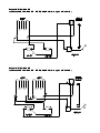
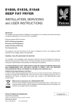
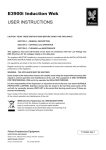
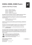
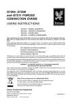
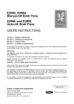
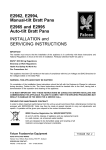
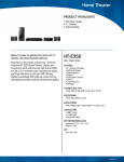
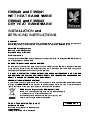
E350/40 and E350/41
WET HEAT BAINS MARIE
E350/42 and E350/43
DRY HEAT BAINS MARIE
INSTALLATION and
SERVICING INSTRUCTIONS
IMPORTANT
The installer must ensure that the installation of the appliance is in conformity with these instructions and
National Regulations in force at the time of installation. Particular attention MUST be paid to -
BS7671 IEE Wiring Regulations
Electricity at Work Regulations
Health And Safety At Work Act
Fire Precautions Act
This appliance has been CE-marked on the basis of compliance with the Low Voltage and EMC Directives for
the voltages stated on the Data Plate
WARNING -THIS APPLIANCE MUST BE EARTHED
On completion of the installation these instructions should be left with the Engineer-in-Charge for reference
during servicing. Further to this, The Users Instructions should be handed over to the User, having had a
demonstration of the operation and cleaning of the appliance.
IT IS MOST IMPORTANT THAT THESE INSTRUCTIONS BE CONSULTED BEFORE INSTALLING AND
COMMISSIONING THIS APPLIANCE. FAILURE TO COMPLY WITH THE SPECIFIED PROCEDURES MAY
RESULT IN DAMAGE OR THE NEED FOR A SERVICE CALL.
PREVENTATIVE MAINTENANCE CONTRACT
In order to obtain maximum performance from this unit we would recommend that a Maintenance Contract be
arranged with SERVICELINE. Visits may then be made at agreed intervals to carry out adjustments and
repairs. A quotation will be given upon request to the contact numbers below.
WEEE Directive Registration No. WEE/DC0059TT/PRO
At end of unit life, dispose of appliance and any replacement parts
in a safe manner, via a licenced waste handler.
Units are designed to be dismantled easily and recycling of all
material is encouraged whenever practicable.
Falcon Foodservice Equipment
HEAD OFFICE AND WORKS
Wallace View, Hillfoots Road, Stirling. FK9 5PY. Scotland.
SERVICE CONTACT -
PHONE - 01438 363 000 FAX - 01438 369 900
T100666 Ref. 2
Warranty Policy Shortlist
Warranty does not cover :Correcting faults caused by incorrect installation of a product.
Where an engineer cannot gain access to a site or a product.
Repeat commission visits.
Replacement of any parts where damage has been caused by misuse.
Engineer waiting time will be chargeable.
Routine maintenance and cleaning.
Gas conversions i.e. Natural to Propane gas.
Descaling of water products and cleaning of water sensors where softeners/conditioners are not fitted, or are
fitted and not maintained.
Blocked drains.
Independent steam generation systems.
Gas, water and electrical supply external to unit.
Light bulbs.
Re-installing vacuum in kettle jackets.
Replacement of grill burner ceramics when damage has been clearly caused by misuse.
Where an engineer finds no fault with a product that has been reported faulty.
Re-setting or adjustment of thermostats when unit is operating to specification.
Cleaning and unblocking of fryer filter systems due to customer misuse.
Lubrication and adjustment of door catches.
Cleaning and Maintenance
Cleaning of burner jets
Poor combustion caused by lack of cleaning
Lubrication of moving parts
Lubrication of gas cocks
Cleaning/adjustment of pilots
Correction of gas pressure to appliance.
Renewing of electric cable ends.
Replacement of fuses
Corrosion caused by use of chemical cleaners.
SECTION 1 - INSTALLATION
UNLESS OTHERWISE STATED, PARTS WHICH HAVE BEEN PROTECTED BY THE MANUFACTURER
ARE NOT TO BE ADJUSTED BY THE INSTALLER
SECTION 2 - ASSEMBLY
1.1 MODEL NUMBER, NETT WEIGHTS
and DIMENSIONS
MODEL
WIDTH DEPTH HEIGHT WEIGHT WEIGHT
mm
mm
mm
kg
lbs
E350/40
350
650
305
20
44
E350/41
700
650
305
33
73
E350/42
350
650
305
18
39
E350/43
700
650
305
30
67
All Weights are nett, exclusive of containers.
1.2 SITING
The unit should be installed on a table or similar
surface. Alternatively it may be installed upon the
purpose designed floor-stand, supplied by Falcon. If it
is to be positioned in close proximity to a wall,
partition etc., a clearance of 25mm at the rear and
sides should be observed. A vertical clearance of
600mm between the top of the appliance and any
overlying combustible surface must also be provided.
1.3 ELECTRICAL SUPPLY
These appliance are for use on single phase AC
supplies only.
1.4 SUPPLY CONNECTION
The cable entry is located at rear of appliance and is
suitable for 20mm conduit. The connection to mains
electric supply must be made through a suitable
isolating switch with a contact separation of at least
3mm in all poles. Wiring should conform to I.E.E.
regulations and the installation should satisfy local
supply authority.
Warning
THESE APPLIANCES MUST BE EARTHED.
A suitable terminal is provided for this purpose and
must be used.
Note
Precautions regarding earth leakage must be taken
during installation.
1.5 ELECTRICAL RATINGS
Electrical ratings are as stated on appliance data
plate.
1.6 CONTROLS
All models are controlled by a single thermostat.
2.1 E350/40 and E350/41 Wet Bains Marie
a) Remove feet from bag and screw into locations on
unit base prior to positioning.
b) Place unit in position and carefully level it, using
feet adjusters if it is to be mounted on a counter or
table. If it is to be installed a stand, please refer to
instructions supplied with accessory.
c) The appliance is supplied complete and ready to
be connected to supply mains.
d) To gain access to terminals, the front facia panel
has to be removed. Remove two fixings in upper
flange of panel, below overhanging hob. Ease top
of panel forward then lift it upward to release lower
fixings.
e) Terminal block is now accessible and supply
cables can be fed to it through inbuilt conduit tube.
f) After connecting unit, replace facia panel and
ensure that bottom location is properly assembled.
g) Do not install water well at this stage and switch on
unit to check that elements, thermostat and pilot
lamps are functioning correctly. The RED neon is lit
when power is available i.e. isolating switch is
closed. The AMBER neon is lit when elements are
ON, it will go out whenever thermostat opens.
h) After satisfactory completion of installation,
demonstrate the method of operation to kitchen
staff and point out location of isolating switch for
use in an emergency or during routine cleaning etc.
2.2 E350/42 and E350/43 Dry Bains Marie
a) Position unit and carefully level it using feet
adjusters on a counter or table. If it is to be
installed upon a stand, please refer to instructions
supplied with stand.
b) The appliance is supplied complete and ready to
connect to mains supply.
c) To gain access to terminals, proceed as follows:
Lift out container supports at top of unit and also
perforated spreader plate which covers element.
Remove drip shield which covers terminal box at rear
of appliance.
Remove terminal box cover.
d) Terminal block is now accessible and supply
cables can be connected.
e) After connections have been made, replace all
components, noting that large holes in spreader
plate must face toward rear.
f) Switch unit ON. Check that elements are heating
and that pilot lamps are functioning. The RED neon
is lit when power is available, i.e. isolating switch is
closed. The AMBER neon is lit when elements are
ON, and will go out whenever thermostat opens.
g) After satisfactory completion of installation,
demonstrate method of operation to kitchen staff.
Point out location of isolating switch for use in an
emergency or during routine cleaning.
SECTION 3 - SERVICING
BEFORE ATTEMPTING ANY MAINTENANCE,
SWITCH OFF AT THE MAINS ISOLATING SWITCH
AND TAKE STEPS TO ENSURE THAT IT IS NOT
INADVERTENTLY SWITCHED ON.
When ordering spares, please quote model number,
serial number and voltage as stamped on data plate
at rear of appliance.
3.1 CONTROL PANEL - To Remove
3.1.1 Wet Heat Models
a) Remove two screws in upper flange of panel. i.e.
below front hob overhang.
b) Ease panel forward at top, then lift it slightly to
release lower locations.
c) Move panel forward.
3.1.2 Dry Heat Models
a) Remove drip tray located below control panel.
b) Remove two screws in upper flange of control
panel.
c) Allow panel to drop down slightly to release lower
fixings and remove panel.
3.2 THERMOSTAT - To Remove
3.2.1 Wet Heat Models
a) Remove control panel. (See Section 3.1.1)
b) Remove well complete with containers etc. by
grasping handles and lifting vertically.
c) Remove thermostat phial from fixing clips.
d) Pull off thermostat connections, noting locations.
e) Pull off knob and remove two screws.
f) From inside controls compartment, undo gland nut
which secures thermostat tube to boss. Push phial
down into comparment and remove thermostat.
g) Upon re-fitting, ensure insulating sleeving covers
capillary tube. Neatly coil excess length over a
suitable object of approximately 50mm diameter.
Ensure that earth-bonding terminal is re-fitted
underneath thermostat fixing lug.
3.2.2 Dry Heat Models
a) Remove control panel. (See Section 3.1.2)
b) Remove any containers etc.
c) Remove thermostat phial from fixing clips.
d) Pull off thermostat connections, noting locations.
e) Pull off thermostat knob and remove two fixing
screws.
f) From inside controls compartment, undo gland nut
which secures capillary tube to boss. Push phial
downward into compartment and remove
thermostat.
g) When refitting, ensure that insulating sleeving is
fitted to capillary tube. Neatly coil excess length
over a suitable round object of approximately
50mm diameter.
Ensure that earth-bonding terminal is re-fitted below
thermostat fixing lug.
3.3 PILOT LAMPS - To Remove
All Models
a) Remove control panel. (See Section 3.1)
b) Pull off lamp connections.
c) Undo nut that secures lamp at rear to remove.
Fit replacement in reverse order.
3.4 HEATING ELEMENTS - To Remove
3.4.1 Wet Heat Models
a) Remove control panel (See Section 3.1.1)
b) Remove water well etc. (See Section 3.2.1)
c) From inside of controls compartment, remove
element connections.
d) Remove fixings that secure element and remove it.
e) When replacing element, ensure that earth
bonding wires are reconnected to element flanges
using shakeproof washers below nuts.
3.4.2 Dry Heat Models
a) Remove control panel. (See Section 3.1.2)
b) Remove all containers, supporting components
and perforated spreader panel which covers
element.
c) Remove element connections from inside controls
compartment.
d) Undo fixings that secure element and remove it.
Replace all parts in reverse order. Take care to refit
serrated washers below element fixing nuts.
Reposition spreader plate with large holes facing
toward rear.
E350/40 WET BAIN MARIE
and E350/42 DRY BAIN MARIE - WIRING DIAGRAM (Drawing No. AW32477/B)
E350/41 WET BAIN MARIE
and E350/43 DRY BAIN MARIE - WIRING DIAGRAM (Drawing No. AW32476/B)