1
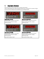
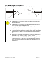
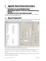
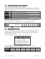
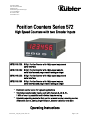
Fritz Kübler GmbH
Zähl- und Sensortechnik
Postfach 34 40
D-78023 Villingen-Schwenningen
Tel.: 07720-3903-0
Fax: 07720-21564
www.kuebler.com
Position Counters Series 572
High Speed Counters with two Encoder Inputs
6.572.0116.D05: 6 Digit Position Counter with 4 high-speed outputs and
serial interface
6.572.0116.D95: 6 Digit Position Counter with 4 high-speed outputs,
serial interface and programmable analogue output
6.572.0118.D05: 8 Digit Position Counter with 4 high-speed outputs and
serial interface
6.572.0118.D95
8 Digit Position Counter with 4 high-speed outputs,
serial interface and programmable analogue output
• Electronic counter series for high-end applications
• Two independent encoder inputs, each with channels A, /A, B, /B ,
1 MHz of counting capability and individual impulse scaling
• Selectable operating modes for fast position or event counter, summing counter,
differential counter, cutting length indicator, diameter calculator and more
Operating Instructions
6.572.116_118_07a_e.doc / Dez-10
Page 1 / 43
Safety Instructions
• This manual is an essential part of the unit and contains important hints about
function, correct handling and commissioning. Non-observance can result in
damage to the unit or the machine or even in injury to persons using the
equipment!
• The unit must only be installed, connected and activated by a qualified electrician
• It is a must to observe all general and also all country-specific and applicationspecific safety standards
• When this unit is used with applications where failure or maloperation could cause
damage to a machine or hazard to the operating staff, it is indispensable to meet
effective precautions in order to avoid such consequences
• Regarding installation, wiring, environmental conditions, screening of cables and
earthing, you must follow the general standards of industrial automation industry
• - Errors and omissions excepted –
Version:
Description:
6.572._03c/wb/wb_05/07
6.572._03d/wb/wb_02/08
First edition
Corrections: Brightness control, parameters F04.30-31,
Clarification “Hysteresis”
Dual counter mode (mode 10), small corrections
Dual counter mode (mode 10), small corrections
Several amendments, additional clarifications
Parameter "Display Update Time", correction of default values,
amendments, serial codes added to parameter lists
6.572._03d/wb/wb_09/08
6.572._05a/wb/wb_09/08
6.572._05b/wb/wb_12/08
6.572._07a/wb/wb_12/10
6.572.116_118_07a_e.doc / Dez-10
Page 2 / 43
Table of Contents
1.
2.
3.
Available Models............................................................................................................ 4
Introduction..................................................................................................................... 5
Electrical Connections..................................................................................................... 6
3.1.
3.2.
3.3.
3.4.
3.5.
3.6.
3.7.
4.
Operating Modes of the Counter ...................................................................................10
4.1.
4.2.
4.3.
4.4.
4.5.
4.6.
4.7.
4.8.
4.9.
5.
Summary of the Menu ...................................................................................................24
Description of the Parameters.......................................................................................27
Clarification of the Counter Setting Functions ..............................................................36
Appendix: Serial Communication Details.......................................................................37
7.1.
7.2.
7.3.
7.4.
8.
9.
Normal Operation ..........................................................................................................20
General Setup Procedure...............................................................................................20
Direct Fast Access to Preselections ..............................................................................21
Change of Parameter Values on the Numeric Level .....................................................22
Code Protection against Unauthorized Keypad Access ................................................23
Return from the Programming Levels and Time-Out Function ......................................23
Reset all Parameters to Factory Default Values ...........................................................23
Menu Structure and Description of Parameters.............................................................24
6.1.
6.2.
6.3.
7.
“Single Mode” (Encoder 1 only): F07.062 = 0................................................................11
“Sum Mode” (Encoder 1 + Encoder 2): F07.062 = 1 ......................................................12
Differential Mode (Encoder 1 – Encoder 2): F07.062 = 2 ..............................................13
Master Counter and Integrated Batch Counter: F07.062 = 3 ........................................14
Evaluation of the Real Cutting Length: F07.062 = 4 ......................................................15
Diameter Calculation with Winding Rolls: F07.062 = 5 ................................................16
Radius Calculation with Winding Rolls: F07.062 = 6 ....................................................17
Monitor for Slip, Torsion, Skew Position, Shaft Fracture: F07.062 = 9.........................18
Dual Counter, Two Independent Counters for Encoders 1 and 2: F07.062 = 10 ..........19
Keypad Operation ..........................................................................................................20
5.1.
5.2.
5.3.
5.4.
5.5.
5.6.
5.7.
6.
Power Supply ...................................................................................................................8
Auxiliary Outputs for Encoder Supply..............................................................................8
Impulse Inputs for Incremental Encoders ........................................................................8
Control Inputs Cont.1 – Cont.4 ........................................................................................8
Switching Outputs K1 – K4..............................................................................................9
Serial Interface ................................................................................................................9
Fast Analogue Output (models xxx.D95 only)..................................................................9
Setup of the Counter by PC............................................................................................37
Automatic and Cyclic Data Transmission......................................................................38
Communication Protocol................................................................................................38
Serial Register Codes ....................................................................................................40
Specifications ................................................................................................................42
Dimensions ....................................................................................................................43
6.572.116_118_07a_e.doc / Dez-10
Page 3 / 43
1.
Available Models
The 6.572 counter series includes the four models shown below.
These models provide fully similar properties and functions, except with the number of digits,
the size of the LED display and the availability of an analogue output.
P
L1
L2
K1
K2
K3
K4
Model 6.572.0116.D05:
6-decade display, 14,22 mm size (0.56’’),
4 fast-switching transistor outputs,
RS232 serial link
P
L1
L2
K1
K2
K3
K4
Model 6.572.0116.D95
6-decade display, 14,22 mm size (0.56’’),
4 fast-switching transistor outputs,
RS232 serial link,
high-speed analogue output
6.572.116_118_07a_e.doc / Dez-10
P
L1
L2
K1
K2
K3
K4
Model 6.572.0118.D05:
8-decade display, 14,22 mm size (0.56’’),
4 fast-switching transistor outputs,
RS232 serial link
P
L1
L2
K1
K2
K3
K4
Model 6.572.0118.D95
8-decade display, 14,22 mm size (0.56’’),
4 fast-switching transistor outputs,
RS232 serial link,
high-speed analogue output
Page 4 / 43
2.
Introduction
The counters of series 6.572 have been designed to close a gap with multiple counting
applications, which cannot be accomplished by the normal industrial electronic counters
available on the market.
A continual demand for increasing production speeds and higher precision at the same time
results in counting frequencies exceeding the conventional frequency range.
Particularly with fast running procedures it is most important to also have fast response of the
switching outputs or the analogue output.
Many applications require to evaluate the signals of two incremental measuring systems, and
to compare the results with respect to the sum or the difference or the ratio of the two
positions. This is e.g. necessary for calculation of diameters of winding rolls etc.
These are some of the reasons why the new counter series 6.572 have been designed.
• This manual provides all necessary instructions for operation of the
counter models presented in the previous chapter. All statements are
valid for any of the four models, except where especially remarked.
• For full serial access to the unit by PLC or IPC or by a remote operator
terminal, supplementary instructions are available upon request.
6.572.116_118_07a_e.doc / Dez-10
Page 5 / 43
7
Ana .ou t 20 mA
Ana .ou t +/-10V
8 9 10 11 12 13 14 15 16
Enco der1 *
*) Exam ple s hows wiring
for enco ders with 5 volts
power s upply and RS422
line dri ver output
E ncoder 2*
Digita l
Contro l
Inputs
RS2 32
+24
19
+5 18
A 24
/A 8
B 23
/B 7
- 20
+24
3
+5
2
A 22
/A
6
B 21
29 Com+ (K1 - K4)
26 K1 out
25 K2 out
10 K3 out
Fast
transistor
outputs
9 K4 out
16 +/-10V
/B 5
- 4
Cont1
28
Cont2 27
Cont3
12
Cont4
11
15 20 mA
32 0V, GND
Fast
analogue
outputs
(mod els xxx.D95 only)
RxD
14
TxD 30
GND 31
17
1
+ Power sup ply ∼
∼
6.572.116_118_07a_e.doc / Dez-10
GND
Encoder1 B
Encoder1 A
K2 out
K1 out
Cont. 2
Cont. 1
Com+ (K1-K4 )
TxD (RS2 32)
GND
17 18 19 20 21 2 2 23 24 25 26 27 28 29 30 31 32
+Vin
+5,2V au x.out
+24 V au x.out
X2
3 4 5 6
GND
Enco der2 B
Encod er2 A
X1
1 2
GND
Enco der2 /B
Enco der2 /A
Encoder1 /B
Encoder1 /A
K4 out
K3 out
Con t. 4
Cont. 3
PROG
RxD (RS232)
Electrical Connections
GND
+5,2V aux. out
+24V a u x. out
3.
13
24 V DC
24 V AC
PROG
Page 6 / 43
Terminal
01
02
03
04
05
06
07
08
09
10
11
12
13
14
15
16
17
18
19
20
21
22
23
24
25
26
27
28
29
30
31
32
Name
GND
+5,2V out
+24V out
GND
Encoder2, /B
Encoder2, /A
Encoder1, /B
Encoder1, /A
K4 out
K3 out
Cont.4
Cont.3
(PROG)
RxD
Ana.out 20 mA
Ana.out +/-10V
+Vin
+5,2V out
+24V out
GND
Encoder2, B
Encoder2, A
Encoder1, B
Encoder1, A
K2 out
K1 out
Cont.2
Cont.1
Com+ (K1-K4)
TxD
GND
GND
Function
Common Ground Potential (0V)
Aux. output 5.2V/150 mA for encoder supply
Aux. output 24V/120 mA for encoder supply
Common Ground Potential (0V)
Encoder 2, channel /B (B inverted)
Encoder 2, channel /A (A inverted)
Encoder 1, channel /B (B inverted)
Encoder 1, channel /A (A inverted)
Output K4, transistor PNP 30 volts, 350 mA
Output K3, transistor PNP 30 volts, 350 mA
Digital control input
Digital control input
(for download of new firmware only, not for general use)
Serial RS232 interface, input (Receive Data)
Analogue current output 0 – 20 mA or 4 – 20 mA (xxx.D95)
Analogue voltage output -10V … 0 … +10V (xxx.D95)
Power supply input, +17 – 40 VDC or 24 VAC
Aux. output 5,2V/150 mA for encoder supply
Aux. output 24V/120 mA for encoder supply
Common Ground Potential (0V)
Encoder 2, channel B (non-inverted)
Encoder 2, channel A (non-inverted)
Encoder 1, channel B (non-inverted)
Encoder 1, channel A (non-inverted)
Output K2, transistor PNP 30 volts, 350 mA
Output K1, transistor PNP 30 volts, 350 mA
Digital control input
Digital control input
Common positive input for transistor outputs K1-K4
Serial RS232 interface, output (Transmit Data)
Common Ground Potential (0V)
Common Ground Potential (0V) for DC or AC power supply
*) 120 mA and 150 mA are per encoder, i.e. total maximum currents are 240 mA and 300 mA
6.572.116_118_07a_e.doc / Dez-10
Page 7 / 43
3.1. Power Supply
The counter accepts both, a 17 – 40 volts DC power or a 24 volts AC power for supply via
terminals 17 and 1. The current consumption depends on the level of the input voltage and
some internal conditions; therefore it can vary in a range from 100 – 200 mA
(aux. currents taken from the unit for encoder supply not included).
3.2. Auxiliary Outputs for Encoder Supply
Terminals 2 and 18 provide an auxiliary output with approx. +5.2 volts DC (300 mA totally).
Terminals 3 and 19 provide an auxiliary output with approx. +24 volts DC (240 mA totally)
3.3. Impulse Inputs for Incremental Encoders
All input characteristics of the impulse inputs can be set by the parameter menu, for each of
the encoders separately. Depending on the application the unit can accept single channel
information (input A only) or quadrature information (A / B, 90°). The following settings are
possible:
• Symmetric input (differential) according to RS422 standard
(min. differential voltage 1 V)
• TTL inputs at a level of 3.0 to 5 volts (differential, with inverted signal)
• TTL inputs at a level of 3.0 to 5 volts (single-ended) *)
• HTL signals at a 10 – 30 volts level
(alternatively differential with inverted signals A, /A, B, /B, or single-ended A, B only)
• Impulses from photocells or proximity switches etc. providing a HTL level (10 – 30 volts)
• Proximity switches according to NAMUR (2-wire) standard
(may need additional remote resistor)
All encoder input lines are internally terminated by pull-down resistors ( 8,5 kΩ ).
Where encoders with pure NPN outputs are used, corresponding pull-up resistors must be
available inside the encoder or externally to ensure proper function (1 kΩ ... 3,3 kΩ).
3.4. Control Inputs Cont.1 – Cont.4
These inputs can be configured for various remote functions like Reset, Set, Latch, and Inhibit
or switch-over purpose.
All control inputs require HTL level. They can be individually set to either NPN (switch to -) or
PNP (switch to +) characteristics. For applications where edge-triggered action is needed, the
menu allows to set the active edge (rising or falling). Control inputs also accept signals with
Namur (2-wire) standard. For reliable operation the minimum pulse width on the control inputs
should be 50 μsec.
*) requires special settings of the threshold parameters, see “Special parameters F04”
6.572.116_118_07a_e.doc / Dez-10
Page 8 / 43
3.5. Switching Outputs K1 – K4
All units provide four preselections and outputs with programmable switching characteristics.
K1 – K4 are fast-switching and short-circuit-proof transistor outputs with a switching capability
of 5 – 30 volts / 350 mA each. The switching voltage of the outputs must be applied remotely
to the common input (Com+, terminal 29)
3.6. Serial Interface
The serial RS232 interface can be used for the following purposes:
• Set-up of the unit by PC (if desirable), by means of the OS32 PC software
• Change of parameters during operation
• Readout of actual counter or other values by PLC or PC
The figure below explains the connection between the series 6.572 counters and a PC using the
standard Sub-D-9 serial connector
screen
Counter
14
30
31
RxD
TxD
RxD
TxD
GND
2
3
PC
5
(Sub-D-9)
For more details about serial communication, please refer to the appendix of section 7.
3.7. Fast Analogue Output (models xxx.D95 only)
The analogue output provides a voltage output of +/- 10 volts (load = 3 mA), and a current
output of 0 – 20 mA or 4 – 20 mA (load = 0 – 270 Ohms). All output characteristics like
beginning of conversion range, output swing etc. are freely programmable via menu. The
response time of the analogue output is less than 1 msec. (time from encoder event to
analogue out). The resolution is 14 bits.
Please note that extensive serial communication with the unit may temporary increase the
analogue response time.
6.572.116_118_07a_e.doc / Dez-10
Page 9 / 43
4.
Operating Modes of the Counter
For best survey, all parameters of the unit are arranged in 13 expedient groups, named
“F01” - “F13”. Depending on the application, only a few of these groups may be important,
while all other groups may be irrelevant for your specific application.
This section describes possible applications and operating modes of the counter.
The operation mode can be set under parameter group F07, parameter # F07.062.
The following counting functions are available:
Operating Mode
F07.062
0
1
2
3
4
5
6
7
8
9
10
Counter Function
Single counter mode, encoder 1 only
Summing counter mode (encoder 1 + encoder 2)
Differential counter mode (encoder 1 - encoder 2)
Master counter and batch counter
Display of the actual cutting length with cutting "on the fly" applications
Roll diameter calculation with winding rolls
Roll radius calculation with winding rolls
n.a.
n.a.
Control of slip, torsion, skew position, shaft fracture etc.
Dual counter, two independent counters for encoder 1 and encoder 2
•
It is possible to cycle the display between the five reading modes shown in
the following function tables, by pressing one of the front keys or by using
one of the control inputs (you must have assigned the display scroll function
to one of the keys or the inputs under menu F06, to activate the scrolling of
the display). LEDs L1 and L2 indicate which of the values is actually displayed.
•
Scrolling of the display from one reading mode to another will not affect the
function of the preselection outputs K1 – K4
•
The analogue output (models xxxD95) can be assigned to any of the readings
accessible in the display, by a special parameter. Scrolling of the display from
one reading mode to another will not affect the analogue output.
•
As far as the selected counter mode also allows reading out the minimum and
maximum values or the positions of the last change of direction, please note
that the unit latches these extreme values in time periods of 1 msec. only.
Therefore the display of memorized extreme positions may include some
inaccuracy with high counting frequencies (real extreme value may lie
between two records)
Full details about parameter arrangement and function can be found under section 6.
6.572.116_118_07a_e.doc / Dez-10
Page 10 / 43
4.1. “Single Mode” (Encoder 1 only): F07.062 = 0
Only the inputs of encoder 1 are active, signals on the encoder 2 inputs will not be evaluated.
Besides the actual counter value, the unit also records minimum and maximum values as well
as the last positions of change of direction.
All 4 preselections are related to the actual counter value.
1
2
3
4
5
Display
Actual counter value
Minimum value since last reset
Maximum value since last reset
Position of last change of direction (up and low)
Only lower point of change of direction (F04.030 = 0)
Only upper point of change of direction (F04.030 = 1)
L1 (red)
-blinking fast
-blinking slow
--
L2 (yellow)
--blinking fast
-blinking slow
1 23 4 56
or
Encode r 1
Cont.1
Typica l applications:
- fast preset counter
- position counter with m emorized
points of change of direction
- event counter, incrementing or dec rementing
6.572.116_118_07a_e.doc / Dez-10
Cont.4
Res et, Preset, Inhibit etc.
Page 11 / 43
4.2. “Sum Mode” (Encoder 1 + Encoder 2): F07.062 = 1
Both inputs encoder 1 and encoder 2 are active. From both values the unit forms the sum, with
consideration of the individual encoder scaling factors. Where the encoder signal also provides
direction information, this information will be considered by a corresponding sign of the count.
Without direction information (channel A only) both encoder values will be added up. The final
result can once more be scaled into user-friendly engineering units by means of the special
scaling parameters in parameter group F07.
Besides the actual counter value and the sum, the unit also records minimum and maximum
values of the sum.
Preselections K1 and K2 are related to the actual counter value of encoder 1 only.
Preselections K3 and K4 are related to the actual sum result (encoder 1 + encoder 2)
Display
Actual sum encoder 1 + encoder 2
Minimum value of the sum (since last reset)
Maximum value of the sum (since last reset)
Actual counter value of encoder 1 alone
Actual counter value of encoder 2 alone
1
2
3
4
5
Sum of two
event counts
L1 (red)
-blinking fast
-blinking slow
-s = s0 + s1 + s2
s0
s2
s1
L2 (yellow)
--blinking fast
-blinking slow
Sum of two
positions
Two-stage
hydraulic c ylinder
+
123456
Encode r 1
Cont.1
Enco der 2
Cont.4
Reset, Pres et, Inhibit etc.
6.572.116_118_07a_e.doc / Dez-10
+
123 456
Encoder 1
Cont.1
Encode r 2
Cont.4
Reset, Preset, Inhibit etc.
Page 12 / 43
4.3. Differential Mode (Encoder 1 – Encoder 2): F07.062 = 2
Both inputs encoder 1 and encoder 2 are active. From both values the unit forms the difference,
with consideration of the individual encoder scaling factors.
Where the encoder signal also provides direction information, this information will be
considered by a corresponding sign of the count. Without direction information (channel A only)
encoder 1 will increment and encoder 2 will decrement the counter. The final result can once
more be scaled into user-friendly engineering units by means of the special scaling parameters
in parameter group F07.
Besides the actual counter value and the difference, the unit also records minimum and
maximum values of the difference.
Preselections K1 and K2 are related to the actual counter value of encoder 1 only.
Preselections K3 and K4 are related to the actual differential result (encoder 1 - encoder 2)
Display
Actual difference encoder 1 - encoder 2
Minimum value of the difference (since last reset)
Maximum value of the difference (since last reset)
Actual counter value of encoder 1 alone
Actual counter value of encoder 2 alone
1
2
3
4
5
Difference of
two event counts
L1 (red)
-blinking fast
-blinking slow
--
Gap w idth d = s1 - s2
s2
d
L2 (yellow)
--blinking fast
-blinking slow
Difference of
two positions
s1
123456
+
Encoder 1
Cont.1
Encoder 2
Cont.4
Reset, Pres et, Inhibit etc.
6.572.116_118_07a_e.doc / Dez-10
123 456
-
Encoder 1
Cont.1
Encode r 2
C ont.4
Reset, Preset, Inhibit etc.
Page 13 / 43
4.4. Master Counter and Integrated Batch Counter: F07.062 = 3
This counter mode can be used for cut-to lengths applications, cyclic production flows, packing
procedures etc. While the master counter takes care of the correct number of impulses per
product, the background batch counter counts the number of products produced.
This mode assumes that the automatic reset function has been activated for the master
counter, providing restart from zero every time the preset value has been reached.*)
Only the inputs of encoder 1 are active (master counter).
Every time the master counter reaches its preset value, it restarts from zero and the batch
counter increments by 1. ***)
The batch counter can be decremented by separate external signal, when one of the keys or
control inputs has been defined correspondingly. **)
Besides the master counter and the batch counter, the unit also records minimum and
maximum values of the batch count.
Presets K1 and K2 are related to the actual counter value of encoder 1.
Presets K3 and K4 are related to the actual value of the batch counter.
1
2
3
4
5
Display
Actual counter value of batch counter
Minimum value of batch counter (since last reset)
Maximum value of batch counter (since last reset)
Actual counter value of master counter (encoder 1)
Actual counter value of batch counter
L1 (red)
-blinking fast
-blinking slow
--
L2 (yellow)
--blinking fast
-blinking slow
*)
Example: If 500 impulses on encoder 1 are necessary for 1 product:
a. Set F01.000 to 500 (preset level 1)
b. Set F10.089 = 1.00 sec. (output pulse time K1)
c. Set F10.097 = 2 or 4 (automatic restart from 0)
**)
Select parameter group F06 and assign the special command “13” to any of the keys or
control inputs for remote decrementing of the batch counter
***)
As a matter of course the counting sense can also be reversed, i.e. the main counter
loads a preset value, counts down towards zero, increments the batch counter when
reaching zero and sets to the preset value again
6.572.116_118_07a_e.doc / Dez-10
Page 14 / 43
4.5. Evaluation of the Real Cutting Length: F07.062 = 4
This mode uses encoder 1 as a length counter and encoder 2 is not active. All counting occurs
in the background and is not visible in the display. The counter gets started and stopped by
remote control signals, and the final counting result appears in the display (frozen) whilst the
counter already executes the next cycle in the background.
For remote start and stop signals the inputs Cont.1 and Cont.2 must be used, therefore these
inputs are no more available for other purpose. All assignments of the signals and the active
edges (rising or falling) can individually be set to match with the actual measuring situation.
Examples:
use the rising edge of the Cont1 input to latch and reset, This will display your cutting
length as shown in the picture below.
Use Cont1 to start the measuring cycle and Cont2 to stop and latch. This will display the
differential length between the two remote signals
Use the same signal in parallel to Cont1 and Cont2. This e.g. allows to measure a gap or
distance between two products, while the remote signal is high (or low)
This mode is useful to get information about the actual cutting length with applications like
Rotary Cutters, Flying Shears and similar procedures. The automatic reset function is
automatically on in order to ensure that the next measuring cycle will restart at zero.
Besides the actual cutting length the unit also records the extreme length values (minimum and
maximum) of all cuts.
Preselections K1 and K2 are related to the actual counter value of encoder 1 (live background
counter). Preselections K3 and K4 are related to the real cutting lengths shown in the frozen
display. Therefore K3 and K4 can be used for quality sorting purpose (e.g. too short – good –
too long)
1
2
3
4
5
Display
Last actual cutting length (frozen)
Minimum length (since last reset)
Maximum length (since last reset)
Actual background counter (live)
Last actual cutting length (frozen)
Meas uring whee l
L1 (red)
-blinking fast
-blinking slow
-Cutting pulse
L2 (yellow)
--blinking fast
-blinking slow
Measuring of the
real cutting length
123456
Encoder 1
6.572.116_118_07a_e.doc / Dez-10
Cont.1
Page 15 / 43
4.6. Diameter Calculation with Winding Rolls: F07.062 = 5
With this mode encoder 1 receives line impulses from a measuring wheel or a feed roll of a
winder or unwinder application. Furthermore the counter needs one trigger impulse from the
rotation of the winding roll. From both signals the counter can calculate and display the actual
roll diameter. All counting occurs in the background and only updated diameter readings appear
in the display. Encoder 2 is not in use with this application.
The scaling parameters F07.066 and F07.067 are automatically set to the appropriate values
with this application. Parameter F07.068 allows setting a core diameter.
When set to zero, the display will show the full roll diameter.
When set to a core diameter, the display will show the remaining material diameter
(full diameter – core diameter).
Besides the total material length and the actual diameter the unit also records the extreme
diameter values (minimum and maximum) coming up during the process.
Preselections K1 and K2 are related to the actual line counter of encoder 1 (total material
length under the measuring roll).
Preselections K3 and K4 are related to the actual diameter value of the winding roll.
1
2
3
4
5
Display
Actual roll diameter
Minimum diameter (since last reset)
Maximum diameter (since last reset)
Actual value of the line counter
Last counting result of the line counter
feed roll
123456
Enco der 1
6.572.116_118_07a_e.doc / Dez-10
L1 (red)
roll impulse
L2 (yellow)
--
--
blinking fast
-blinking slow
--
-blinking fast
-blinking slow
Calculation of the
diameter of a
winding roll
Display =
co unt / rev.
0.31416
Cont. 1
Page 16 / 43
4.7. Radius Calculation with Winding Rolls: F07.062 = 6
With this mode encoder 1 receives line impulses from a measuring wheel or a feed roll of a
winder or unwinder application. Furthermore the counter needs one trigger impulse from the
rotation of the winding roll. From both signals the counter can calculate and display the actual
radius of the roll. All counting occurs in the background and only updated diameter readings
appear in the display. Encoder 2 is not in use with this application.
The scaling parameters F07.066 and F07.067 are automatically set to the appropriate values
with this application. Parameter F07.068 allows setting a core radius.
When set to zero, the display will show the full radius of the roll.
When set to a core radius, the display will show the remaining radius of the material
(full radius – core radius).
Besides the total material length and the actual radius the unit also records the extreme radius
values (minimum and maximum) coming up during the process.
Preselections K1 and K2 are related to the actual line counter of encoder 1 (total material
length under the measuring roll).
Preselections K3 and K4 are related to the actual radius value of the winding roll.
1
2
3
4
5
Display
Actual roll radius
Minimum radius (since last reset)
Maximum radius (since last reset)
Actual value of the line counter
Last counting result of the line counter
feed roll
123456
Encod er 1
6.572.116_118_07a_e.doc / Dez-10
L1 (red)
roll impulse
L2 (yellow)
--
--
blinking fast
-blinking slow
--
-blinking fast
-blinking slow
Calculation of the
radius of a
winding roll
Display = co unt / rev.
0.62832
Cont.1
Page 17 / 43
4.8.
Monitor for Slip, Torsion, Skew Position, Shaft Fracture:
F07.062 = 9
This counter mode is a special version of the Differential Counter described previously. As a
major difference, in this mode all four preselections and outputs (K1 – K4) refer exclusively to
the differential count, and also a programmable slip function has been added.
Before forming the difference, each of the two encoder inputs is scaled individually according
to the setting of the impulse scaling factor. If applicable, the differential result can once more
be scaled to engineering units with use of the final scaling operands.
Since preselections and outputs can be set to positive and negative values as well, it is also
possible to use the unit for simple synchronous control purpose of two drives, by temporary
accelerating or breaking one of the drives when lagging or leading the other. Typical examples
are large rolling gates or lifting ramps or gantry cranes, driven by several independent motors.
Some applications (e.g. with couplings) can accept (or even may require) a certain slip.
For slip control with adjustable slip parameters, an automatic timer function can be
programmed to reset the counters periodically.
Multi-purpose parameter F04.030 is used to set the reset cycle in seconds (00.0 = no automatic
reset, 99.9 = reset every 99.9 seconds)
Since with slip applications, where the automatic reset function is switched on, the real time
display of the counter may be very confusing, multi-purpose parameter F04.031 works to reduce
the update rate of the display
(0 = real-time display, 1 = 8 msec., 2 = 16 msec., 3 = 32 msec., 4 = 64 msec. etc.)
Besides the differential count, the display can be scrolled to indicate also the following values:
Display
L1 (red)
L2 (yellow)
1 Differential count (encoder1 – encoder2)
--2 Minimum difference (since last reset)
blinking fast
-3 Maximum difference (since last reset)
-blinking fast
4 Encoder 1 only
blinking slow
-5 Encoder 2 only
-blinking slow
Encoder
123456
Encoder 1
Encoder 2
Encoder
Motor
6.572.116_118_07a_e.doc / Dez-10
Alert 1
Alert 4
Control of Shaft and Gearbox Fracture
Page 18 / 43
4.9. Dual Counter, Two Independent Counters for Encoders 1 and 2:
F07.062 = 10
Both encoder inputs operate fully independent one from the other, with individual scaling,
evaluation and display. Also each counter can be set or reset individually.
Both counters are treated equally, except with recording of minimum and maximum values.
With regard to this function one of the two counters has to be declared as the "main counter".
The unit will record the min/max values of the main counter only and no min/max values will be
available of the other counter.
Attribution of the main counter uses the Multi-Purpose Parameter 1 (F04.030)
F04.030 = 0
F04.030 = 1
:
:
Encoder 1 represents the main counter (default)
Encoder 2 represents the main counter
Presets K1 and K2 are always related to the main counter.
Presets K3 and K4 refer to the other of the two counters
With many applications it may be desirable to toggle the display only between encoder 1 and
encoder 2, without needing to pass over all the other values every time. Therefore the MultiPurpose Parameter 2 (F04.031) can be used to choose between one of the following two display
sequences:
F04.031 = 0
1
2
3
4
5
:
Standard display sequence with all display values* (default)
Display
Main counter (encoder 1 or encoder 2)
Minimum value of main counter (since last reset)
Maximum value of main counter (since last reset)
Counter of encoder 1
Counter of encoder 2
L1 (red)
-blinking fast
-blinking slow
--
L2 (yellow)
--blinking fast
-blinking slow
F04.031 = 1 :
Short display sequence to toggle between encoders 1 and 2 only
Display
L1 (red)
L2 (yellow)
1 Counter of encoder 1
blinking slow
-2 Counter of encoder 2
-blinking slow
*) Units with analogue output (xxxD95 series) will always generate the analogue
signal from one of the lines 1 to 5, according to assignment by parameter F08.079.
This is also valid when the short display sequence is used.
6.572.116_118_07a_e.doc / Dez-10
Page 19 / 43
5.
Keypad Operation
An overview of all parameters and explanations can be found under section 6.
The menu of the unit uses four keys, hereinafter named as follows:
P
PROG
UP
DOWN
ENTER
Key functions depend on the actual operating state of the unit. Essentially we have to describe
three basic states:
• Normal operation
• General setup procedure
• Direct fast access to preselections and set values
5.1. Normal Operation
In this mode the unit operates as a counter according to the settings defined upon setup. All
front keys may have customer-defined functions according to the specifications met in the
keypad definition menu F06 (e.g. scrolling of the display, Reset, Inhibit etc.)
5.2. General Setup Procedure
The unit changes over from normal operation to setup level when keeping the PROG key down
for at least 2 seconds. Thereafter you can select one of the parameter groups F01 to F13.
Inside the group you can now select the desired parameter and set the value according to need.
After this you can either set more parameters or return to the normal operation.
The following sequence of key operations explains how to change
Parameter number 052 of group F06 from the original value of 0 to 8
6.572.116_118_07a_e.doc / Dez-10
Page 20 / 43
Step
00
State
Key action
Normal operation
01
02
P
Level:
Parameter group
Display
Counting
> 2 sec.
F01
Display of the
Parameter group
5x
F02 … F06
Select group # F06
F06.050
Confirmation of F06.
The first parameter of this
group is F06.050
Select parameter 052
03
04
Level:
Parameter numbers
2x
05
06
09
10
F06.051…
F06.052
0
Level:
Parameter values
07
08
Comment
Level:
Parameter numbers
Level:
Parameter groups
Normal operation
8x
P
P
P
1 …. 8
F06.052
F06
Counting
Parameter 052 appears in
display, actual setting is 0
Setting has been modified
from 0 to 8
Save the new setting (8)
Return to level parameter
groups
Return to normal operation
During the general setup procedure all counter activities remain
disabled. New parameter settings become active after return to
normal operation only.
5.3. Direct Fast Access to Preselections
To get to the fast access routine, please press both
P
and
at the same time
This will access the parameter group F01 right away. To change the settings follow the same
procedure as already described above. Besides the advantage of direct access, the fundamental
difference to general setup is the following:
During the fast access procedure all counter functions remain fully active.
Access is limited to preselections; no other parameters can be changed.
6.572.116_118_07a_e.doc / Dez-10
Page 21 / 43
5.4. Change of Parameter Values on the Numeric Level
The numeric range of the parameters is up to 6 digits with 6-decade models and up to 8 digits
with 8 decade models. Some of the parameters may also include a sign. For fast and easy
setting or these values the menu uses an algorithm as shown subsequently. During this
operation the front keys have the following functions:
P
PROG
Saves the actual value
shown in the display and
returns to the parameter
selection level
UP
Increments the
highlighted
(blinking) digit
DOWN
Decrements the
highlighted
(blinking) digit
ENTER
Shifts the cursor (blinking
digit) one position to the
left, or from utmost left
to right
With signed parameters the left digit scrolls from 0 to 9 and then shows “–„ (negative) and
“-1“ (minus one). The example below shows how to change a parameter from the setting 1024
to the new setting 250 000 (using a 6 decade model).
This example assumes that you have already selected the parameter group and the parameter
number, and that you actually read the parameter value in the display.
Highlighted digits appear on colored background.
Step
Display
00
001024
Key action
4x
01
02
03
04
05
06
07
08
09
10
001020
001020
001000
001000
000000
000000
050000
050000
250000
6.572.116_118_07a_e.doc / Dez-10
Comment
Display of actual parameter setting, last
digit is highlighted
Scroll last digit down to 0
Shift cursor to left
2x
Scroll highlighted digit down to 0
2x
Shift curser 2 positions left
Scroll highlighted digit down to 0
Shift cursor left
5x
Scroll highlighted digit up to 5
Shift cursor left
2x
P
Scroll highlighted digit up to 2
Save new setting and return to the
parameter number level
Page 22 / 43
5.5. Code Protection against Unauthorized Keypad Access
Parameter group F05 allows to define an own locking code for each of the parameter menus.
This permits to limit access to certain parameter groups to specific persons only.
When accessing a protected parameter group, the display will first show “CODE” and wait for
your entry. To continue keypad operations you must now enter the code which you have stored
before, otherwise the unit will return to normal operation again.
After entering your code, press the ENTER key and keep it down until the unit responds.
When your code was correct, the response will be “YES” and the menu will work normally.
With incorrect code the response will be “NO” and the menu remains locked.
5.6. Return from the Programming Levels and Time-Out Function
At any time the PROG key sets the menu one level up and finally returns to normal operation.
The same step occurs automatically via the time-out function, when during a period of 10
seconds no key has been touched.
Termination of the menu by automatic time-out will not store new settings, unless they have
already been stored by the PROG key after editing.
5.7. Reset all Parameters to Factory Default Values
Upon special need it may be desirable to set all parameters back to their original factory
settings (e.g. because you have forgotten your access code, or by too many change of settings
you have achieved a complex parameter state). Default values are indicated in the parameter
tables shown later.
To reset the unit to default, please take the following steps:
•
Switch power off
•
Press
•
Switch power on while you keep down both keys
and
simultaneously
Where you decide to take this action, please note that all parameters and settings
will be lost, and that you will need to run a new setup procedure again.
6.572.116_118_07a_e.doc / Dez-10
Page 23 / 43
6.
Menu Structure and Description of Parameters
All parameters are arranged in a reasonable order of functional groups (F01 to F13)
You must only set those parameters which are really relevant for your specific application.
Unused parameters can remain as they actually are.
6.1. Summary of the Menu
This section shows a summary of the parameter groups, with an assignment to the functional
parts of the unit.
Group
Function
Group
Function
F01
000
001
002
003
004
005
Preselection values
Preselection K1
Preselection K2
Preselection K3
Preselection K4
Preset value encoder 1
Preset value encoder 2
F02
010
011
012
013
014
015
Definitions for encoder 1
Encoder properties
Edge count select x1, x2, x4
Counting direction up/down
Impulse scaling Factor
Multiple count factor
Round-loop cycle definition
F03
018
019
020
021
022
023
Definitions for encoder 2
Encoder properties
Edge count select x1, x2, x4
Counting direction up/down
Impulse scaling Factor
Multiple count factor
Round-loop cycle definition
F04
026
027
028
029
030
031
Special functions
Digital input filters
Power down memory
Input threshold 1
Input threshold 2
Multi-purpose parameter
Display cycle time for Slip control
F05
033
034
035
036
037
038
039
040
041
042
043
044
045
Keypad protection codes
F01
F02
F03
F04
F05
F06
F07
F08
F09
F10
F11
F12
F13
F06
050
051
052
053
054
055
056
057
058
059
060
Key commands and control inputs
Key UP
Key DOWN
Key ENTER
Input Cont.1, switching characteristics
Input Cont.1, assignment of function
Input Cont.2, switching characteristics
Input Cont.2, assignment of function
Input Cont.3, switching characteristics
Input Cont.3, assignment of function
Input Cont.4, switching characteristics
Input Cont.4, assignment of function
6.572.116_118_07a_e.doc / Dez-10
Page 24 / 43
Group Function
Group
Function
F07
062
063
064
065
066
067
068
069
070
Basic settings
Mode of operation
Decimal point encoder 1
Decimal point encoder 2
Decimal point combined <1,2>
Multiplication factor <1,2>
Division factor <1,2>
Display offset <1,2>
Brightness of LED display %
Display Update Time
F08
074
075
076
077
078
079
Analogue output definitions (xxx.D95)
Output current or voltage
Start value of conversion
End value of conversion
Output swing
Zero offset
Assignment of the analogue output
F09
081
082
083
084
085
086
Serial communication
Serial device address
Baud rate
Data format
Serial protocol selection
Timer for auto-transmission
Serial code of transmit data
F10
089
090
091
092
093
094
095
096
097
098
099
100
101
102
103
104
105
106
Switching features and preselections
K1 (static or pulse)
K2 (static or pulse)
K3 (static or pulse)
K4 (static or pulse)
Hysteresis K1
Hysteresis K2
Hysteresis K3
Hysteresis K4
Preselection mode K1
Preselection mode K2
Preselection mode K3
Preselection mode K4
Preset mode
Output polarity (N.O. or N.C.)
n.a.
n.a.
Start-up Inhibit of Outputs
Calculation of trailing preselections
6.572.116_118_07a_e.doc / Dez-10
Page 25 / 43
F11
Mode of Linearisation
F11.108 Linearisation mode counter 1
F11.109 Linearisation mode counter 2
F12
F12.114
F12.115
F12.144
F12.145
F13
F13.146
F13.147
F13.176
F13.177
Table of Linearisation Counter 1
First interpolation point (x1 value)
First interpolation point (y1 value)
etc. -------->
Last interpolation point (x16 value)
Last interpolation point (y16 value)
Table of Linearisation Counter 2
First interpolation point (x1 value)
First interpolation point (y1 value)
etc. -------->
Last interpolation point (x16 value)
Last interpolation point (y16 value)
The following schematics shows how in principle the parameter blocks are assigned to the
various elements and functions of the counter.
E ncoder 1
Encoder 2
Cont1
Cont2
Cont3
Cont4
Digita l
Contro l
Inputs
RS232
F02
F03
F07F11F12F13
123456
P
up
dn
K1 out
F01 K2 out
K3 out
F10 K4 out
ENT
F05 F06
F06
Fast
An a log ue
20 mA
Ou tputs
(mod els x xx.D95)
+/-10V
F08
F09
Fast
Switch ing
Outputs
Where you find highlighted indications in the following parameter listings,
this indicates that the setting range depends on the model and is 6 digits
with 6 decade models and 8 digits with 8 decade models
6.572.116_118_07a_e.doc / Dez-10
Page 26 / 43
6.2. Description of the Parameters
6.2.1.
F01
000
001
002
003
004
005
Preselections and presets
Preselection K1
Preselection K2
Preselection K3
Preselection K4
Preset value encoder 1
Upon internal or external command the encoder 1
counter will set to this value
Preset value encoder 2
Upon internal or external command the encoder 2
counter will set to this value
6.2.2. Definitions for encoder 1
F02
010 Encoder properties
0= Differential signals A, /A, B, /B (2 x 90°)
*)
1= HTL signals A, B (2 x 90°) single-ended
2= Differential signals A, /A for count
*)
Differential signals B, /B to indicate static
direction (if available)
3= HTL signal A (single-ended) for count
HTL signal B (single-ended) to indicate static
direction (if available)
011 Edge counting
0= Simple (x1)
1= Double (x2)
2= Full quadrature (x4)
012 Counting direction
0= Up when A leads B
1= Down when A leads B
013 Impulse scaling factor
Multiplier for input impulses
014 Impulse multiplier
Multiple count of every impulse
015 Round-loop cycle
0= Unlimited counting range
xxx Round-loop operation in a range 0 - xxx
Range
-199 999 - 999 999
-199 999 - 999 999
-199 999 - 999 999
-199 999 - 999 999
-199 999 - 999 999
Default Ser.
1 000
00
2 000
01
3 000
02
4 000
03
000 000 04
-199 999 - 999 999
000 000
05
Range
0…3
Default
1
Ser.
A0
0…2
0
A1
0…1
0
A2
0.00001 - 9.99999
1.00000
A3
001 - 99
001
A4
0 - 999 999
0
A5
*) Applies for any kind of differential signals, no matter if RS422 or TTL level or HTL level
6.572.116_118_07a_e.doc / Dez-10
Page 27 / 43
6.2.3. Definitions for encoder 2
F03
Range
Default
018 Encoder properties
0…3
1
0= Differential signals A, /A, B, /B (2 x 90°)
*)
1= HTL signals A, B (2 x 90°) single-ended
2= Differential signals A, /A for count
*)
Differential signals B, /B to indicate static
direction (if available)
3= HTL signal A (single-ended) for count
HTL signal B (single-ended) to indicate static
direction (if available)
019 Edge counting
0…2
0
0= Simple (x1)
1= Double (x2)
2= Full quadrature (x4)
020 Counting direction
0…1
0
0= Up when A leads B
1= Down when A leads B
0.00001 - 9.99999 1.00000
021 Impulse scaling factor
Multiplier for input impulses
022 Impulse multiplier
001 - 99
001
Multiple count of every impulse
023 Round-loop cycle
0 - 999 999
0
0= Unlimited counting range
xxx Round-loop operation in a range 0 - xxx
Ser.
A8
A9
B0
B1
B2
B3
*) Applies for any kind of differential signals, no matter if RS422 or TTL level or HTL level
6.2.4. Special functions
F04
026 Digital input filter
027 Power-down memory
0= Off. Counter resets to zero after power down
1= On. Counter stores last counting result
028 Trigger threshold for encoder1 inputs **)
029 Trigger threshold for encoder2 inputs **)
030 Multi-purpose parameter, function depending on
application as shown under 4.1, 4.8 and 6.3
031 Display cycle time with slip measuring applications
(see 4.8)
**)
Range
0…3
0-1
Default
0
0
Ser.
B6
B7
30 … 250
30 … 250
0 … 999
166
166
0
B8
B9
C0
0 … 999
0
C1
Must be set to the default value (166) with any kind of input signals, except if exceptionally singleended TTL signals should be used. Only in this case setting 35 is required.
6.572.116_118_07a_e.doc / Dez-10
Page 28 / 43
6.2.5.
F05
033
034
035
036
037
038
039
040
041
042
043
044
045
Keypad protection codes
Range
Protected group F01
Protected group F02
Protected group F03
Protected group F04
Protected group F05
Protected group F06
Protected group F07
Protected group F08
Protected group F09
Protected group F10
Protected group F11
Protected group F12
Protected group F13
6.2.6. Key commands and control input definitions
F06
050 Function assignment to key „UP“
0= No function
1= Reset counter 1 (encoder 1)
1 – 999 999 =
Protection code
for the actual
group
Default
0
0
0
6079
0
0
0
0
0
0
0
0
0
Ser.
C3
C4
C5
C6
C7
C8
C9
D0
D1
D2
D3
D4
D5
Range
0 … 14
Default
0
Ser.
E0
0 … 14
0
E1
0 … 14
0
E2
0 = no protection
(Clears also points of change of direction)
051
052
*)
2= Reset counter 2 (encoder 2)
3= Reset counter 1 and counter 2
4= Set counter 1 to Set Value 1 *)
5= Set counter 2 to Set Value 2 *)
6= Set both counters to Set Value *)
7= Inhibit counter 1
8= Inhibit counter 2
9= n.a.
10= Start serial transmission
11= Reset minimum/maximum records
12= Scroll actual display
13= Special command (depends on counter mode)
14= n.a.
Function assignment to key „DOWN“
See key „UP“
Function assignment to key „ENTER“
See key „UP“
Parameter F10.101 defines the source of the Set Value (see 6.3)
6.572.116_118_07a_e.doc / Dez-10
Page 29 / 43
F06
053
(continued)
Switching characteristics of input „Cont.1“
0=
1=
2=
3=
4=
5=
6=
7=
054
2=
3=
4=
5=
6=
7=
8=
9=
10=
11=
12=
13=
14=
055
Default
0
Ser.
E3
0 … 14
0
E4
0…7
0
E5
0 … 14
0
E6
0…7
0
E7
0 … 14
0
E8
0 ... 3
0
E9
0
F0
NPN (switch to -) function active LOW
NPN (switch to -) function active HIGH
NPN (switch to -) rising edge
NPN (switch to -) falling edge
PNP (switch to +), function active LOW
PNP (switch to +), function active HIGH
PNP (switch to +), rising edge
PNP (switch to +), falling edge
Function assignment to input „Cont.1“
0=
1=
Range
0…7
No function
Reset counter 1 (encoder 1)
(Clears also points of change of direction)
Reset counter 2 (encoder 2)
Reset counter 1 and counter 2
Set counter 1 to Set Value 1 *)
Set counter 2 to Set Value 2 *)
Set both counters to Set Value *)
Inhibit counter 1
Inhibit counter 2
n.a.
Start serial transmission
Reset minimum/maximum records
Scroll actual display
Special command (depends on counter mode)
Hardware keypad interlock
Switching characteristics of input „Cont.2“
See „Cont.1“ (F06.053)
056
Function assignment to input „Cont.2“
See „Cont.1“ (F06.054)
057
Switching characteristics of input „Cont.3“
See „Cont.1“ (F06.053)
058
Function assignment to input „Cont.3“
See „Cont.1“ (F06.054)
059
Switching characteristics of input „Cont.4“
0=
1=
2=
3=
060
= NPN (switch to -), active LOW
= NPN (switch to -), active HIGH
= PNP (switch to +), active LOW
= PNP (switch to +), active HIGH
Function assignment to input „Cont.4“
static switching
functions only
0 … 14
See „Cont.1“ (F06.054)
Unconnected NPN inputs are always HIGH (internal pull-up resistor)
Unconnected PNP inputs are always LOW (internal pull-down resistor)
*) Parameter F10.101 defines the source of the Set Value (see 6.3)
6.572.116_118_07a_e.doc / Dez-10
Page 30 / 43
6.2.7. Basic settings
F07
062 Operation mode of the counter
0=
1=
2=
3=
4=
5=
6=
7=
8=
9=
10=
063
064
065
066
067
068
069
070
6.2.8. Analogue output definitions (models xxx.D95 only)
F08
074 Output format
075
076
077
078
079
Ser.
F2
0…5
0…5
0…5
0.0001 – 9.9999
0.0000 – 9.9999
-199999 - 999999
0…4
0
0
0
1.0000
0
0
0
F3
F4
F5
F6
F7
F8
F9
0.005 - 9.999
0.005
G0
Range
0…3
Default
0
Ser.
G4
-199999 - 999999
0
G5
-199999 - 999999
10 000
G6
0 … 1000
-10000 - 10000
0…4
1000
0
G7
G8
G9
100% of maximum brightness
80% of maximum brightness
60% of maximum brightness
40% of maximum brightness
20% of maximum brightness
Display Update Time (sec.)
0=
1=
2=
3=
Default
0
„Single“, encoder 1 only
„Sum“, encoder 1 + encoder 2
„Differential“, encoder 1 – encoder 2
Master counter and batch counter
Measuring of real cutting length
Calculation of roll diameters
Calculation of roll radius
n.a.
n.a.
Slip-, torsion- skew position monitor
Dual counter, independent counters 1 and 2
Decimal point position of encoder 1
Decimal point position of encoder 2
Decimal point position combined <1&2>
Scaling factor for combined values <1&2>
Divider for combined values *)
Offset value for combined values
Brightness of the 7-segment LED display
0=
1=
2=
3=
4=
Range
0 … 10
Voltage – 10 V… + 10 V
Voltage 0 ….. +10 V
Current 4 – 20 mA
Current 0 – 20 mA
Beginning of the conversion range
Display value to generate 0 volts or 0/4 mA
End of the conversion range
Display value to generate 10 volts or 20 mA
Analogue output swing (1000 = 10 V or 20 mA)
Analogue zero offset (mV, zero displacement)
Analogue output assignment
(according to lines 1 – 5 of the display scrolling function)
(Line1) … (Line5)
*) Setting 0,0000 will skip the whole recalculation and therefore speed up the cycle time
6.572.116_118_07a_e.doc / Dez-10
Page 31 / 43
6.2.9. Serial communication parameters
F09
081 Serial device address (unit number)
082 Serial baud rate
0=
9600 Baud
1=
4800 Baud
2=
2400 Baud
3=
1200 Baud
4=
600 Baud
5= 19200 Baud
6= 38400 Baud
083 Serial data format
0= 7 Data, Parity even, 1 Stop
1= 7 Data, Parity even, 2 Stop
2= 7 Data, Parity odd, 1 Stop
3= 7 Data, Parity odd, 2 Stop
4= 7 Data, no Parity, 1 Stop
5= 7 Data, no Parity, 2 Stop
6= 8 Data, Parity even, 1 Stop
7= 8 Data, Parity odd, 1 Stop
8= 8 Data, no Parity, 1 Stop
9= 8 Data, no Parity, 2 Stop
084 Serial protocol select *)
0= Transmission = Unit Nr. – Data, LF, CR
1= Transmission = Data, LF, CR
085 Serial timer (sec.) for timer transmissions *)
086 Serial register code of the transmit parameter *)
Range
11 … 99
0…6
Default
11
0
Ser.
90
91
0…9
0
92
0…1
1
H1
0.000 … 99.999
0 … 19
0
14
H2
H3
Range
0.00 … 9.99
Default
0.00
0 … 9999
0
Ser.
H6
H7
H8
H9
I0
I1
I2
I3
*) for more details please see appendix in section 7
6.2.10. Switching characteristics and presets
F10
089 Pulse time (sec.) output K1 (0 = static output)
090 Pulse time (sec.) output K2 (0 = static output)
091 Pulse time (sec.) output K3 (0 = static output)
092 Pulse time (sec.) output K4 (0 = static output)
093 Switching hysteresis K1 (display units) *)
094 Switching hysteresis K2 (display units) *)
095 Switching hysteresis K3 (display units) *)
096 Switching hysteresis K4 (display units) *)
*) The switching point equals to the preset value and the return point is displaced by the hysteresis setting
6.572.116_118_07a_e.doc / Dez-10
Page 32 / 43
F10
097
098
099
100
101
102
103
104
105
106
Switching characteristics K1
0= active with display ≥ preselection
1= active with display ≤ preselection
2= active with display ≥ preselection, 0→counter.
Remaining errors are cancelled
3= active with display ≤ preselection,
Set→counter. Remaining errors are cancelled
4= active with display ≥ preselection, 0→counter
Remaining errors added to following cycle
5= active with display ≤ preselection,
Set→counter
Remaining errors added to following cycle
Switching characteristics K2 (see K1, F10.097)
Switching characteristics K3 (see K1, F10.097)
Switching characteristics K4 (see K1, F10.097)
Set value of the counter
0= Set value = Preset (1 or. 2)
1= Set value = Preselection K1 or K2
K1 – K4 outputs N.C or N.O *)
K1= binary value 1
K2= binary value 2
K3= binary value 4
K4= binary value 8
Bit = 0: Output switches ON when active (N.O.) *)
Bit = 1: Output switches OFF when active (N.C.) *)
n.a.
n.a.
Start-up Inhibit of timed K1-K4 outputs
after power-up
Switch point calculation with trailing preselections
0:
1:
2:
3:
K1=>K1,
K2=>K2,
K1=>K1, K1-K2=>K2,
K1=>K1,
K2=>K2,
K1=>K1, K1-K2=>K2,
Range
0…5
Default
0
Ser.
I4
0…5
0
0…1
0
I5
I6
I7
I8
0 … 15
0
I9
0
0
Q1
Q2
0
Q3
Remark:
≥ and ≤ refer to
positive values
and are inversely
with negative
values
Example: Setting
9 means that K1
and K4 operate
N.O. and K2 and
K3 operate N.C *)
0 = pulses enabled
1 = pulses disabled
0…3
K3=>K3,
K4=>K4
K3=>K3,
K4=>K4
K3=>K3, K3-K4=>K4
K3=>K3, K3-K4=>K4
Example: if set to “1” the K2 switching point would be
substituted by the difference K1 - K2 (i.e. F00.000 - F00.001)
*) N.O. means “normally open”, saying that the corresponding output is normally switched
OFF and will switch on when the assigned event happens.
*) N.C. means “normally closed”, saying that the corresponding output is normally switched
ON and will switch off when the assigned event happens
6.572.116_118_07a_e.doc / Dez-10
Page 33 / 43
6.2.11. Parameters for Linearization
F11 Modes of Linearization
Range
0–2
108 Mode of linearization for counter 1 (encoder 1)
0 = Linearisation off
(see drawings on
1 = Linearisation is defined for the numeric range
next page)
from 0 to +999 999 only and negative values
will appear as a mirror of the positive values
2 = Linearisation is defined over the full range from 199 999 to +999 999
0–2
109 Mode of linearization for counter 2 (encoder 2)
0 = Linearisation off
(see drawings on
1 = Linearisation is defined for the numeric range
next page)
from 0 to +999 999 only and negative values
will appear as a mirror of the positive values
2 = Linearisation is defined over the full range from 199 999 to +999 999
F12
114
115
116
117
144
145
F13
146
147
148
149
176
177
Table of linearization for counter 1 (encoder 1)
First interpolation point, (x0, original value)
First interpolation point, (y0, replacement value)
Second interpolation point (x1, original value)
Second interpolation point (y1, replacement value)
etc. ---->
Last interpolation point, (x15, original value)
First interpolation point, (y15, replacement value)
Table of linearization for counter 2 (encoder 2)
First interpolation point, (x0, original value)
First interpolation point, (y0, replacement value)
Second interpolation point (x1, original value)
Second interpolation point (y1, replacement value)
etc. ---->
Last interpolation point, (x15, original value)
Last interpolation point, (y15, replacement value)
6.572.116_118_07a_e.doc / Dez-10
Default
0
Ser.
J1
0
J2
Range
Default
-199999 - 999999
0
Ser.
J7
J8
J9
K0
M7
M8
Range
Default
-199999 - 999999
0
Ser.
M9
N0
N1
N2
P9
Q0
Page 34 / 43
6.2.12. Hints for using the linearization function
The subsequent drawing explains the difference between the modes of linearisation.
y
y
(x0)= -1000
(y0)= 900
Linearisation Mode = 2
Linearisation Mode = 1
(x15)= 1000
(y15)= 800
x
(x8)= 0
(y8)= 750
x
(x0)= 0
(y0)= 0
(x15)= +1000
(y15)= - 600
(Mirror)
•
x-registers are to set the numeric counter value that the unit would display
without linearisation
•
y-registers are to set the numeric value that should be displayed instead (i.e.
the y3 setting will replace the display value x3
•
between the interpolation points the unit automatically uses linear
interpolation
•
x- registers have to use continuously increasing values, e.g. the lowest display
value must be set to register x0, and the highest display value must be set to
x16
•
Independent of the selected linearisation mode, the possible setting range of
all registers x0, y0, … x16, y16 is always -199999 … 999999.
•
For measuring values outside of the defined linearisation range, please note:
If the measuring value is lower than x0, the linearisation result will always
be y0. If the measuring value is higher than x16, the linearisation result will
always be y16.
6.572.116_118_07a_e.doc / Dez-10
Page 35 / 43
6.3. Clarification of the Counter Setting Functions
This section is only important if you intend to preset the counter to values different from zero.
The menu provides several options to reset one or both of counters to zero, or to set the
counters to programmable preset values.
Whilst with a reset command the data loaded into the counter is always zero, the setting
procedure may load data from different locations, depending on the operating mode and some
parameter settings.
The tables below are to clarify which source the counters are using under which conditions.
It would not make any sense to use the Set functions with other counter modes than those
shown below; therefore the tables indicate the reasonable possibilities only.
The triggering event to activate a setting action depends on your parameters and can be
manual (front key or control input) or automatic (when the counter reaches one of the four
preselection thresholds K1 to K4).
The source of the loading data can be one of the two counter preset values set to parameters
F01.004 and F01.005, or any of the four preselection thresholds K1 to K4 adjusted by keypad.
The target for loading data can be either counter1 or counter2
The following abbreviations are used:
P1 = Preset value encoder 1 (F01.004)
C1 = Counter 1
K1 … K4 = Preselections (F01.000 to F01.003)
P2 = Preset value encoder 2 (F01.005)
C2 = Counter 2
Man. = remote set command (key or input)
K1auto etc. = automatic set command triggered by K1
Single mode
Parameter F10.101 = 0
Parameter F10.101 = 1
Trigger event Man. K1auto K2auto K3auto K4auto Man. K1auto K2auto K3auto K4auto
Counter1:
P1xC1 P1xC1 P1xC1 P2xC1 P2xC1 K1xC1 K1xC1 K2xC1 K3xC1 K4xC1
Sum mode
(F07.062 = 2)
Trigger event
Counter 1:
Counter 2:
Diff. mode
(F07.062 = 2)
Trigger event
Counter 1:
Counter 2:
Parameter F10.101 = 0
Man. K1auto
P1xC1 P1xC1
P2xC2
---
K2auto K3auto K4auto Man. K1auto K2auto K3auto K4auto
P1xC1 P1xC1 P1xC1 K1xC1 K1xC1 K2xC1 K1xC1 K2xC1
--P2xC2 P2xC2 K3xC2
----K3xC2 K4xC2
Parameter F10.101 = 0
Man.
P1xC1
P2xC2
K1auto
P1xC1
---
Parameter F10.101 = 1
Parameter F10.101 = 1
K2auto K3auto K4auto Man. K1auto K2auto K3auto K4auto
P1xC1 P1xC1 P1xC1 K1xC1 K1xC1 K2xC1 K1xC1 K2xC1
--P2xC2 P2xC2 K3xC2
----K3xC2 K4xC2
Batch mode
Parameter F10.101 = 0
Parameter F10.101 = 1
(F07.062 = 3)
Trigger event Man. K1auto K2auto K3auto K4auto Man. K1auto K2auto K3auto K4auto
Counter 1:
P1xC1 P1xC1 P1xC1 P1xC1 P1xC1 K1xC1 K1xC1 K2xC1 *xC1 *xC1
Counter 2:
P2xC2
----P2xC2 P2xC2 K3xC2
----K3xC2 K4xC2
*) no change if multi-purpose parameter F04.030 = 0, otherwise C1 cleared to zero
6.572.116_118_07a_e.doc / Dez-10
Page 36 / 43
7.
Appendix: Serial Communication Details
Serial communication with the counter can be used for the following purposes:
• PC setup of the counter, using the OS32 Operator software
• Automatic and cyclic transmission of counter data to remote devices like PC, PLC or
Data Logger
• Communication via PC or PLC, using the communication protocol
This section describes the essential and basic communication features only. Full details are
available from the special SERPRO manual.
7.1. Setup of the Counter by PC
Connect the counter to your PC as shown in section 3.6 of this manual. Start the OS32 Operator
software. After a short initializing time you will see the following screen:
If your screen remains empty and the headline of your PC says „OFFLINE“, select „Comms“ of
the menu bar and check your serial communication settings.
The edit field on the left shows all actual parameters and provides full editing function. The
„File“ menu allows to store complete sets of parameters for printout or for download to a
counter.
When editing parameters, please use the ENTER key of your PC after each entry, to ensure
storage of your data to the counter.
6.572.116_118_07a_e.doc / Dez-10
Page 37 / 43
7.2. Automatic and Cyclic Data Transmission
Set any cycle time unequal to zero to parameter F09.085.
Set the serial access code of the register you would like to transmit to parameter F09.086. In
theory you could transmit any of the internal registers by serial link, however only the following
registers make really sense:
F09.086 = 6
F09.086 = 7
F09.086 = 8
F09.086 = 9
F09.086 = 10
F09.086 = 14
:
:
:
:
:
:
Actual count value of counter 1 (encoder 1)
Actual count value of counter 2 (encoder 2)
Actual analogue output voltage (models xxx.E95)
Latest minimum value from the minimum record register
Latest maximum value from the maximum record register
Actual display value as shown on the LED display
Dependent on the setting of parameter F09.084 the unit transmits one of the following data
strings, under cycle control of the timer:
(xxxx = counter data*, LF = Line Feed <hex. 0A>, CR = Carriage Return <hex 0D>)
F09.084 = 0 :
F09.084 = 1 :
(Unit No.)
1
1
+/+/-
X
X
X
X
X
X
X
X
X
X
X
X
LF
LF
CR
CR
*) Leading zeros will not be transmitted
7.3. Communication Protocol
When communicating with the unit via protocol, you have full read/write access to all internal
parameters, states and actual counter values. The protocol uses the DRIVECOM standard
according to DIN ISO 1745. A list with the most frequently used serial access codes can be
found in the subsequent section.
To request data from the counter, the following request string must be sent:
EOT
AD1 AD2 C1 C2 ENQ
EOT = Control character (Hex 04)
AD1 = Unit address, High Byte
AD2 = Unit address, Low Byte
C1 = Register code to read, High Byte
C2 = Register code to read, Low Byte
ENQ = Control character (Hex 05)
The example shows how to request for transmission of the actual count of counter 1
(register code :6), from a unit with unit address 11:
ASCII-Code:
EOT
Hexadezimal:
04
Binär:
0000 0100
6.572.116_118_07a_e.doc / Dez-10
1
31
0011 0001
1
31
0011 0001
:
3A
0011 1010
6
36
0011 0110
ENQ
05
0000 0101
Page 38 / 43
Upon correct request, the counter will respond:
STX C1 C2 x x x x x x x ETX BCC
STX = Control character (Hex 02)
C1 = Register code to read, High Byte
C2 = Register code to read, Low Byte
xxxxx = Counter data *)
ETX = Control character (Hex 03)
BCC = Block check character
*) Leading zeros will not be transmitted
The Block-Check-Character represents the EXCLUSIVE-OR function of all characters from
C1 to ETX (both comprised).
To write to a parameter, you have to send the following string:
EOT AD1 AD2 STX C1 C2 x x x x x x x ETX BCC
EOT = Control character (Hex 04)
AD1 = Unit address, High Byte
AD2 = Unit address, Low Byte
STX = Control character (Hex 02)
C1 = Register code to write, High Byte
C2 = Register code to write, Low Byte
xxxxx = Value of the parameter
ETX = Control character (Hex 03)
BCC = Block check character
Upon correct receipt the unit will respond by ACK, otherwise by NAK.
Every new parameter sent will first go to a buffer memory, without affecting the actual
counting process. This function enables the user, during normal counting operation, to prepare
a complete new parameter set in the background.
To activate transmitted parameters, you must write the numeric value “1” to the “
Activate Data“ register. This immediately activates all changed settings at the same time.
Where you like the new parameters to remain valid also after the next power up of the unit,
you still have to write the numeric value “1” to the „Store EEProm“ register. This will store all
new data to the EEProm of the counter. Otherwise, after power down the unit would return
with the previous parameter set.
6.572.116_118_07a_e.doc / Dez-10
Page 39 / 43
7.4. Serial Register Codes
7.4.1. Communication Commands
Function
Activate Data
Store EEProm
Code
67
68
These commands have to be sent to the unit every time after one or several new parameters
have been transmitted, in order to activate or to store the new values. Both commands are
"dynamic", i.e. it is sufficient to just send the data value "1" to the corresponding code position.
Example: send the command "Activate Date" to the counter with Unit No. 11:
ASCII
Hex
EOT
04
1
31
1
31
STX
02
6
36
7
37
1
31
ETX
03
BCC
33
7.4.2. Control Commands
To activate control commands (e.g. Reset) by serial link, the following steps are required:
a) the desired command has first to be assigned to one of the front keys or control inputs
(any), as described in chapter 6.2.6.
b) after this the corresponding key or input can be virtually activated by serial command (same
as if you would push the key or activate the hardware input). This kind of command provides
static operation. Sending "1" to the corresponding location will switch the command ON, it
will remain on until you send "0" to the same location to switch the command OFF again.
Control Input / Front Key
Input "Cont1"
Input "Cont2"
Input "Cont3"
Input "Cont4"
Key "UP"
Key "DN"
Key "Enter"
Code
59
60
61
62
63
64
65
Example: Parameter F06.054 = 1, i.e. input "Cont1" has been configured for "Reset Counter1"
(see 6.2.6).
Switch the Reset ON (unit number 11):
ASCII
Hex
EOT
04
1
31
1
31
STX
02
5
35
9
39
1
31
ETX
03
BCC
3E
9
39
0
30
ETX
03
BCC
3F
Switch the Reset OFF again (unit number 11):
ASCII
Hex
EOT
04
1
31
1
31
6.572.116_118_07a_e.doc / Dez-10
STX
02
5
35
Page 40 / 43
Function code "10" (Start Serial Transmission) is incompatible with the serial
handling of control commands and will cause communication conflicts
7.4.3. Actual counter data
Nr.
6
7
8
9
10
14
Name
Actual count value of counter 1 (encoder 1)
Actual count value of counter 2 (encoder 2)
Actual analogue output voltage (models xxx.E95)
Latest minimum value from the minimum record register
Latest maximum value from the maximum record register
Actual display value as shown on the LED display
6.572.116_118_07a_e.doc / Dez-10
Code
:6
:7
:8
:9
;0
;4
Page 41 / 43
8.
Specifications
AC power supply
DC power supply
Aux. encoder supply outputs:
:
:
Inputs
:
24 V~ +/-10%, 15 VA
24V- (17 – 40V), approx. 100 mA (+ encoders)
2 x 5,2 VDC, 150 mA each
2 x 24V DC, 120 mA each
2 universal encoder inputs
(internal pull-down resistor, Ri = 8.5 kΩ each channel)
4 digital control inputs HTL (Ri = 3.3 kΩ)
Low < 2.5 V, High > 10 V, min. pulse width 50 μsec.
Counting frequency (per encoder) :
RS422 and TTL differential:
1 MHz
(min. differential voltage 1 V)
Switching outputs (all models)
:
Serial link
Analogue outputs
(models xxx.D95 only)
:
:
Ambient temperature
:
Housing
Display
:
:
Protection class (front side only) :
Protection class rear side
:
Screw terminals
:
Conformity and standards:
HTL single ended:
200 kHz
TTL single-ended:
200 kHz
4 fast power transistors 5 - 30V, 350 mA (b)
Response time < 1 msec. (a),
RS232, 2400 – 38400 Bauds
0/4...20mA (load max.270 Ohm)
0…+/- 10V (load max. 2 mA)
Resolution 14 bits, Accuracy 0.1%
Response time < 1 msec. (a)
Operation:
0 - 45°C ( 32 – 113°F)
Storage:
-25 - +70°C (-13 – 158°F)
Norly UL94 – V-0
6 Digit, LED, high-efficiency red, 14.22 mm (0.56'') or
8 Digit, LED, high-efficiency red 9.15 mm ((0.36'')
IP65
IP20
Cross section max. 1.5 mm²,
EMC 2004/108/EC: EN 61000-6-2
EN 61000-6-3
LV2006/95/EC:
EN 61010-1
(a) Continuous serial communication may temporary increase response times
(b) Diode filtering is mandatory when switching inductive loads
6.572.116_118_07a_e.doc / Dez-10
Page 42 / 43
9.
Dimensions
110,0 (4.331’’)
91,0 (3.583)
48,0 (1.890)
10,0
(.394)
44,0 (1.732)
8,0
(.315)
96,0 (3.780’’)
9,0 (.345)
129,0 (5.079)
140,5 (5.531)
Panel cut out: 91 x 44 mm (3.583 x 1.732’’)
6.572.116_118_07a_e.doc / Dez-10
Page 43 / 43