1
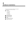
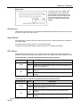
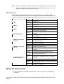
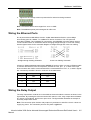
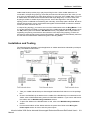
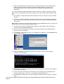
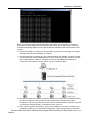
Korenix JetNet 3500 Series Industrial Unmanaged Redundant Ethernet Rail Switch User’s Manual First Edition, July 2005 www.korenix.com Korenix JetNet 3500 Series Industrial Unmanaged Redundant Ethernet Rail Switch User’s Manual Copyright Notice Copyright © 2005 Korenix Technology Co., Ltd. All rights reserved. Reproduction in any form or by any means without permission is prohibited. Table of Contents Chapter 1 Introduction .............................................................................................1-1 Overview........................................................................................................... 1-2 Product Features .............................................................................................. 1-2 Package Checklist ............................................................................................ 1-2 Chapter 2 Hardware Installation ..............................................................................2-1 Introduction....................................................................................................... 2-2 Panel Layouts ..................................................................................................... 2-2 Dimensions ......................................................................................................... 2-3 Reset Button ....................................................................................................... 2-3 DIP Switch........................................................................................................... 2-3 LED Indicators..................................................................................................... 2-4 Wiring the Power Inputs ................................................................................... 2-4 Wiring the Ethernet Ports ................................................................................. 2-5 Wiring the Relay Output ................................................................................... 2-5 Cabling ............................................................................................................. 2-6 DIN-Rail Mounting Installation .......................................................................... 2-6 Wall-Mounting Installation................................................................................. 2-7 Setting Up Super Ring...................................................................................... 2-8 Installation and Testing ..................................................................................... 2-9 Upgrading Firmware ....................................................................................... 2-12 Chapter 3 Troubleshooting ......................................................................................3-1 Appendix A Specifications......................................................................................... A-1 1 Chapter 1 Introduction Welcome to Korenix JetNet 3500 Series Industrial Unmanaged Redundant Ethernet Rail Switch. JetNet 3500 Series includes 2 models: JetNet 3505, and JetNet 3508. JetNet 3500 Series is an unmanaged redundant rail switch that is specially designed for industrial applications. The following topics are covered in this chapter: Overview Product Features Package Checklist Overview Industrial environments are usually more demanding than office environments. Harsh temperature conditions, vibration, dust, etc. all put a test on the quality and reliability of your switches. To survive harsh industrial environments, Korenix provides you with JetNet 3500 Series, an Industrial 5-/8-port Unmanaged Redundant Ethernet Rail Switch. In addition to robust design for coping with demanding industrial environments, JetNet 3500 Series also provides Super Ring technology for network redundancy, and relay output alarm for port breakdown and power failures. JetNet 3500 Series is a cost-effective solution ideal for your industrial applications. JetNet 3500 Series not only gives you high speed data transmission over an Ethernet network, but also provides redundant power inputs and reverse polarity protection. In addition, JetNet 3500 uses an IP30 aluminum case, and has passed several safety certifications, ensuring customers safe and reliable industrial applications. Product Features Korenix JetNet 3500 Series products have the following features: 5-port/8-port 10/100T(X) industrial switch Supports IEEE 802.3 10Base-T, 802.3u 100Base-TX Supports Store-and-Forward switching architecture Supports auto MDI/MDI-X function Supports Super Ring Technology Relay output alarm for port break and power failure Supports IEEE 802.3x flow control ¾ Flow control for full-duplex mode ¾ Back pressure for half-duplex mode Provides redundant dual power inputs Aluminum case with IP30 protection 2K MAC address table DIN-Rail and wall mountable design Package Checklist Korenix JetNet 3500 Series products are shipped with the following items: JetNet 3500 Industrial 5-port/8-port Unmanaged Redundant Ethernet Rail Switch One DIN-Rail clip (attached with the JetNet) One wall mounting plate and six screws User’s manual CD-ROM Quick Installation Guide If any of the above items is missing or damaged, please contact your local sales representative. 1-2 Korenix JetNet 3500 Series Industrial Unmanaged Redundant Ethernet Rail Switch User’s Manual 2 Chapter 2 Hardware Installation This chapter includes information of installation and configuration. The following topics are covered in this chapter: Introduction ¾ Panel Layouts ¾ Dimensions ¾ Reset Button ¾ DIP Switches ¾ LED Indicators Wiring the Power Inputs Wiring the Ethernet Ports Wiring the Relay Output Cabling DIN-Rail Mounting Installation Wall-Mounting Installation Introduction Panel Layouts JetNet 3505 Front View 1 LED indicators 2 RJ45 Ethernet ports 3 DIP Switch JetNet 3508 Front View 1 LED indicators 2 RJ45 Ethernet ports 3 DIP Switch 2-2 Korenix JetNet 3500 Series Industrial Unmanaged Redundant Ethernet Rail Switch User’s Manual Hardware Installation Bottom View The bottom view of the JetNet 3500 Industrial Entry-Level 5-port/8-port Ethernet Rail Switch consists of one terminal block connector with two DC power inputs and one DC IN power jack for an additional AC/DC power adapter. Dimensions JetNet 3500 Industrial 5/8-port Unmanaged Redundant Ethernet Rail Switch dimensions are 54 mm (W) x 135 mm (H) x 105 mm (D). Reset Button The reset button provides users with a quick and easy way to restart and restore the settings to the default values. To restart, press the reset button for 2 seconds and release. To restore to factory default settings, press the button for 5 seconds and release. DIP Switch JetNet 3500 Series provides the 1 set of DIP Switches for configuring the relay output alarm operation modes and the master ring operation mode. The default value of DIP Switches is OFF. JetNet 3505 5-port 10/100TX Unmanaged Redundant Industrial Switch DIP Switch No Status Description OFF Disable the corresponding port Alarm. ON Enable the corresponding port Alarm. If the port’s link fails, the FAULT LED will light up. OFF Disable the switch to be the ring master in the Super Ring topology. ON Enable the switch to be the ring master in the Super Ring topology. P1-P5 P6 JetNet 3508 8-port 10/100TX Unmanaged Redundant Industrial Switch DIP Switch No Status Description OFF Disable the corresponding port Alarm. ON Enable the corresponding port Alarm. If the port’s link fails, the FAULT LED will light up. OFF Disable the switch to be the ring master in the Super Ring topology. ON Enable the switch to be the ring master in the Super Ring topology. P1-P8 P9 Korenix JetNet 3500 Series Industrial Unmanaged Redundant Ethernet Rail Switch User’s 2-3 Manual Note: 1. When the port alarm is enabled, the FAULT LED will light up when port failures occur. 2. After you set the switch to be the ring master in a Super Ring topology, you have to restart this switch for the setting to be activated. LED Indicators There are 6/7 diagnostic LEDs and 8/12 port LEDs located on the front panel of JetNet 3505/3508 Industrial Ethernet Rail Switch. These LED indicators provide administrators with real-time system status. The table below gives descriptions of the function of each LED indicator. LED PWR PWR 1 PWR 2 Status Description Green Power is on. Off No power is being supplied. Green Power is on. Off No power is being supplied. Green Power is on. Off No power is being supplied. Green This switch is the ring master in the Super Ring topology Off This switch is not the ring master in the Super Ring topology Green A network device is detected. Blinks The port is transmitting or receiving packets from the TX (FX) device. Off No device is attached. Orange The port is operating in full-duplex mode. Blinks Collision of packets occurs. Off The port is in half-duplex mode or no device is attached. Orange The port is operating in full-duplex mode. Blinking orange Collision of packets occurs. Off The port is in half-duplex mode or no device is attached. Green A network device is detected. Blinking green The port is transmitting or receiving packets from the TX device. Off No device is attached. R.M. (Ring Master) LNK/ACT of Port 5 or Port 7/8 FDX/COL of Port 5 or Port 7/8 Port Status (Port 1 to 4 or Port 1 to Port 6) Wiring the Power Inputs 1. Insert the positive and negative wires into the V+ and V- contact on the terminal block connector. 2-4 Korenix JetNet 3500 Series Industrial Unmanaged Redundant Ethernet Rail Switch User’s Manual Hardware Installation 2. Tighten the wire-clamp screws to prevent the DC wires from being loosened. Note: The suitable electric wire ranges from 12 to 24 AWG. Note: The additional power jack is designed for office use. Wiring the Ethernet Ports RJ-45 ports with auto MDI-MDI-X function: JetNet 3505/3508 has five/four 10/100 Mbps auto-sensing ports for 10Base-T or 100Base-TX device connection. The UTP ports will auto-detect 10Base-T and 100Base-TX connections. Auto MDI/MDI-X function allows users to connect another switch or workstation without changing straight-through or cross-over cabling. See the figures below for the schematic diagram of straight-through and cross-over cabling. Straight-through Cabling Schematic Cross-over Cabling Schematic All ports of JetNet 3505/3508 support auto-MDI/MDI-X function. When you use an Ethernet cable to connect other devices, such as computers, switches or hubs, pin 1, 2, 3, and 6 of the 8-pin RJ45 connector are used to communicate with the connected devices. Pin1, 2, 3, and 6’s signals are converted by the MDI-X function, as shown in the table below. Pin MDI-X Signals MDI Signals 1 RD+ TD+ 2 RD- TD- 3 TD+ RD+ 6 TD- RD- Wiring the Relay Output The relay output alarm contacts are in the middle of the terminal block connector as shown in the figure below. By inserting the wires and set the DIP switch to “ON”, relay output alarm will detect any power or port failures, and form an open circuit. The figure below illustrates an example of how relay output alarm works. Note: The connection point of alarm relay output only switches on and off the circuit. It does not supply any power. The connection point can only bear 1A@DC24V. Korenix JetNet 3500 Series Industrial Unmanaged Redundant Ethernet Rail Switch User’s 2-5 Manual Fault Alarm Contact The open circuit will form when the power failure or port link failure. 24V DC Buzzer 24V Battery The fault alarm device will send a warning signal to warn the user, ex: alarm sound or flash light. 1. Insert the alarm device’s negative wire into assigned position of the terminal block connector. 2. Tighten the wire-clamp screws to prevent the wires from being loosened. Cabling The cable connection between the JetNet 3505/3508 and the attached devices (switches, hubs, workstations, etc.) must be less than 100 meters (328 ft.) long. DIN-Rail Mounting Installation The DIN-Rail clip is already attached to the JetNet 3500 Series products when packaged. If the DIN-Rail clip is not screwed on the JetNet, follow the instructions and the figure below to attach the DIN-Rail clip to the JetNet. 1. Use the screws to attach the DIN-Rail clip to the rear panel of the JetNet. 2. To remove the DIN-Rail clip, reverse step 1. 2-6 Korenix JetNet 3500 Series Industrial Unmanaged Redundant Ethernet Rail Switch User’s Manual Hardware Installation Follow the steps below to mount the JetNet to the DIN-Rail track. 1. First, insert the upper end of the DIN-Rail clip into the back of the DIN-Rail track from its upper side. 2. Lightly push the bottom of the DIN-Rail clip into the track. 3. Check if the DIN-Rail clip is tightly attached on the track. 4. To remove the JetNet from the track, reverse the steps above. Wall-Mounting Installation Follow the steps below to install the JetNet with the wall mounting plate. 1. To remove the DIN-Rail clip from the JetNet, loosen the screws from the DIN-Rail clip. 2. Place the wall mounting plate on the rear panel of the JetNet. 3. Use the screws to tighten the wall mounting plate onto the JetNet. 4. Use the hook holes at the corners of the wall mounting plate to hang the JetNet onto the wall. 5. To remove the wall mounting plate, reverse the steps above. Korenix JetNet 3500 Series Industrial Unmanaged Redundant Ethernet Rail Switch User’s 2-7 Manual Setting Up Super Ring JetNet 3500 Series supports the Super Ring technology that can help your network system recovery from any of network connection failure within less than 300ms, making your network system more reliable. The Super Ring algorithm is like Spanning Tree Protocol (STP) algorithm, but it has faster recovery time than STP. The following figure is an example of Super Ring application. Super Ring is using the last two UTP ports of JetNet 3505/3508 for setting a Super Ring topology. For JetNet 3505, port 4 and 5 will be used to set up a Super Ring topology, and for JetNet 3508, port 7 and 8 will be used to set up s Super Ring topology. 2-8 Korenix JetNet 3500 Series Industrial Unmanaged Redundant Ethernet Rail Switch User’s Manual Hardware Installation JetNet 3500 Series provides plug-n-play Super Ring function. When JetNet 3500s are not connected in a Super Ring topology, these 5/8 ports serve as Ethernet ports. But, when you set up a group of JetNet 3500s in a Super Ring topology by using port 4/5 of JetNet 3505 or port 7/8 of JetNet 3508, the JetNet 3500s will auto-detect the Super Ring setup. You don’t have to do anything to enable or disable Super Ring function. One of the segments in the Super Ring topology will be considered as the backup path. Normally, this backup path is blocked. But when network disconnection occurs, the blocked backup path will be activated to restore the network connection within less than 300 ms. In a Super Ring topology, you need to set one of the JetNet 3500s to be the Ring Master. To do so, set the DIP Switch located on the front panel of the JetNet 3500 that has R.M. written next to it to ON position (See more details in DIP Switch section). Ring Master will be responsible for negotiating and placing commands to other switches in the Super Ring topology. If there are more than 2 switches that are set to be the Ring Master, JetNet 3500 will automatically select the one that has the smallest MAC address range to be the Ring Master. Installation and Testing The following figure illustrates a typical application of JetNet 3500 Series Industrial 5-port/8-port Entry-Level Ethernet Rail Switch. 1. Take your JetNet Industrial 5/8-port Unmanaged Redundant Rail Switch out of the package box. 2. Check if the DIN-Rail clip is attached to the JetNet. If the DIN-Rail clip is not attached to the JetNet, refer to DIN-Rail Mounting section for DIN-Rail installation. If you want to wall-mount the JetNet, refer to Wall-Mounting Installation section. 3. To place the JetNet on the DIN-Rail track or wall, refer to the Wall-Mounting Installation section. 4. Pull the terminal block off the JetNet and wire the power lines. Refer to the Wiring the Power Inputs section for how to wire the power inputs. Korenix JetNet 3500 Series Industrial Unmanaged Redundant Ethernet Rail Switch User’s 2-9 Manual 5. PWR1 and PWR2 dual power inputs can be connected to power sources simultaneously. When the primary power source fails (the default setting is PWR1), the system will automatically switch to the secondary power source (PWR2), preventing any power interruption. 6. Check the LED for PWR1 and PWR2 to make sure that your JetNet is operating normally. Note: If you are using DC IN power jack to supply power to the JetNet, please check the PWR LED. 7. Use Category 5 straight through Ethernet cables with RJ45 connectors to connect network devices. 8. Connect one side of an Ethernet cable with a RJ45 connector to the JetNet’s Ethernet port (RJ-45 port), and the other side of the Ethernet cable to the network device’s Ethernet port (RJ-45 port). Note: Make sure that the connected network switches support MDI/MDI-X function. If they do not support this function, use a crossover Ethernet cable. 9. Check the port status LED indicator (blinking green) on the JetNet to see if the network connection is successfully established. 10. Power on the host, activate the Command Line mode, and ping the connected Ethernet device to see if it will respond. 11. To enable the “Command Line mode”, click on Run in the Start menu, type Command, and click on OK to continue. 12. Type ping 192.168.1.1 command to check the connection. Here we use IP address 192.168.1.1 as an example. 13. Repeat step 10 to make sure that the connection of each device connected to the JetNet is successfully established. 14. Power on the host, activate the Command Line mode, and ping the connected Ethernet device by typing “ping –t 192.168.1.1” command to see if it will respond. 15. The parameter ”t” allows you to continue to ping the network device, as shown in the figure below. 2-10 Korenix JetNet 3500 Series Industrial Unmanaged Redundant Ethernet Rail Switch User’s Manual Hardware Installation Before you continue, make sure that both PWR1 and PWR2 are successfully connected to power sources. When PWR1 fails, the LED for PWR1 will go out. At that moment, if the ping command is still being replied to, then it proves that the redundant power input function works normally. 16. Exit the Command Line mode, and connect PWR1 power input. At this stage, your JetNet has been tested and the installation is complete. 17. See the figure below for setting up your industrial network with JetNets. Computer A needs to connect several modems simultaneously in order to let a big number of users to access this industrial network. However, Computer A does not have additional COM ports to connect all of the modems. For this reason, we use a network solution. 18. We network enable the modems via serial-to-Ethernet converters, and use Ethernet cables to connect Computer A and converters to the JetNet. Enter Command Line mode in Computer A, and use ping command to see if the connections between Computer A and the converters are working properly, as described in step 10 and 11. 19. Enter Telnet program in Computer A, type in the IP address of one of the converters, and configure the serial port’s communication parameters. Follow this procedure to set up the Korenix JetNet 3500 Series Industrial Unmanaged Redundant Ethernet Rail Switch User’s 2-11 Manual other converters. 20. Install the virtual com port driver, and enter converters’ IP addresses. 21. Click on Computer A’s Control PanelÆDevice Manager, and make sure the system each converter’s IP address is mapped to the corresponding com port. 22. Click on Computer A’s Dialer, and install modem driver. Configure the modem’s corresponding com port as a virtual com port, enter a set of telephone number, and start dialing. Verify that the modem did dial up, and the serial port’s communication parameters are correct. Follow this procedure to verify each converter’s parameters are correct. 23. Click on Computer A’s dial out manager, and change the modem’s setting from dial up to dial in. Follow this procedure to finish each modem’s setting. The industrial network is now established successfully. Computer A is able to connect several converters over the Ethernet via JetNet Series Industrial Ethernet Rail Converter, providing a reliable network environment. Upgrading Firmware 1. Disconnect the JetNet from the network, but keep the JetNet connected with the TFTP server. 2. Set the DIP Switches to the settings as follows: For JetNet 3505: RM = On, P4 = On, P2 =On, P5 = OFF, P3 = OFF, P1 = OFF. For JetNet 3508: RM = On, P8 = Off, P7 = Off, P5 = Off, P4 =On, P3 = OFF, P2 = On, P1 = OFF. 3. Set your TFTP server IP as 192.168.10.250, which is the dedicated TFTP server IP set up in the JetNet. 4. Press the reset button for 5 seconds, and then the PWR1 and PWR2 LEDs will start to flash, showing that TFTP firmware is being upgraded. The JetNet will automatically search for the TFTP server, and update the firmware. Make sure the connection between the JetNet and the TFTP server is intact when the firmware is being upgraded. 5. If any error occurs during the upgrading process, the FAULT LED will flash. Note: Firmware-upgrading process must be performed under the situation that the JetNet is disconnected from the network. 2-12 Korenix JetNet 3500 Series Industrial Unmanaged Redundant Ethernet Rail Switch User’s Manual 3 Chapter 3 Troubleshooting This chapter includes the information on general troubleshooting. Make sure you are using the correct VDC power suppliers (12 to 48 VDC) or power adapters. Do not use power adapters with DC output over 48V. It will damage devices. Select Ethernet cables with specifications suitable for your applications to set up your systems. Ethernet cables are categorized into unshielded twisted-pair (UTP) and shielded twisted-pair (STP) cables. Category 3, 4, 5 Ethernet cables are suitable for systems with 10 Mbps transmission speed. For systems with 100 Mbps transmission speed, Category 5 Ethernet cables are the only suitable specifications for this environment. You also need to make sure that the distance between each node cannot be longer than 100 meters (328 feet). IF the power indicator does not turn on when the power cord is plugged in, you may have a problem with power cord. Than check for loose power connections, power losses or surges at power outlet. IF you still cannot resolve the problem, contact your local dealer for assistance. A Appendix A Specifications Standards IEEE 802.3 10BaseT Ethernet IEEE 802.3u 100BaseT(X)/100BaseF(x) Fast Ethernet IEEE802.3x Flow Control and Back pressure Protocols CSMA/CD Technology Store and Forward switching architecture Transmission Rate 14,880 pps for Ethernet port 148,800 pps for Fast Ethernet port MAC address table size 2K MAC address table Transfer packet size 64 bytes to 1522 bytes (with VLAN tag) Memory Buffer 1Mbits LED Per port: Link/Activity (Green) Full duplex/Collision (Orange) Per unit: Power, Power 1,Power 2(Green), Fault (Yellow), Master (Green) Network Cables 10BaseT: twisted-pair UTP/STP Cat. 3, 4, 5 cable EIA/TIA-568 100-ohm (100m) 100BaseT(X): twisted-pair UTP/STP Cat. 5 cable EIA/TIA-568 100-ohm (100m) Back plane JetNet 3505: 1.0 Gbps JetNet 3508: 1.6 Gbps Throughput JetNet 3505: 0.74 Mpps @ 64 bytes (5TX) JetNet 3508: 1.19 Mpps @ 64 bytes (8TX) Power Supply 12 to 48 VDC, redundant dual DC power inputs with reverse polarity protection, and a removable terminal block for master and slave VDC power inputs. Power consumption JetNet 3505: 3 Watts JetNet 3508: 4.6 Watts Relay alarm current carry ability 1A @ DC 24V Installation DIN-Rail kit and wall mounting panel Operating Temperature 0°C to 60°C Operating Humidity 5 to 95% (non-condensing) Storage Temperature -40 °C to 85°C Storage Relative Humidity 5 to 95%(non-condensing) Dimensions 54 mm (W) x 135 mm (H) x 105mm (D) EMI FCC Class A EMS CE EN61000-4-2, EN61000-4-3, EN61000-4-4, EN61000-4-5, EN61000-4-6, EN61000-4-8, EN61000-4-11 Safety UL, cUL, CE/EN60950 Stability IEC60068-2-32 (Free fall), IEC60068-2-27 (Shock), IEC60068-2-6 (Vibration) A-2 Korenix JetNet 3500 Series Industrial Unmanaged Redundant Ethernet Rail Switch User’s Manual