1
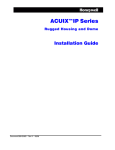
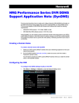
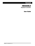
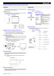
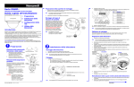
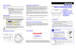
Performance Series 1 THIS SYMBOL INDICATES THAT DANGEROUS VOLTAGE CONSTITUTING A RISK OF ELECTRIC SHOCK IS PRESENT WITHIN THE UNIT. CAUTION RISK OF ELECTRIC SHOCK DO NOT OPEN CAUTION: TO REDUCE THE RISK OF ELECTRIC SHOCK, DO NOT REMOVE THE COVER. NO USER-SERVICEABLE PARTS INSIDE. REFER SERVICING TO QUALIFIED SERVICE PERSONNEL. High Resolution Indoor Fixed Mini-Dome Camera THIS SYMBOL INDICATES THAT IMPORTANT OPERATING AND• MAINTENANCE INSTRUCTIONS ACCOMPANY THIS UNIT. FCC Compliance Statement HD41 Information to the user: This equipment has been tested and found to comply with the limits for a Class A digital device. Pursuant to part 15 of the FCC Rules, these limits are designed to provide reasonable protection against harmful interference when the equipment is operated in a commercial environment. This equipment generates, uses and can radiate radio frequency energy and, if not installed and used in accordance with the instructions, may cause harmful interference to radio communications. Operation of this equipment in a residential area is likely to cause harmful interference in which case the user will be required to correct the interference at his own expense. Quick Installation Guide CAUTION Changes or modifications not expressly approved by the party responsible for compliance could void the user’s authority to operate the equipment. Canadian Compliance Statement This Class A digital apparatus complies with Canadian ICES-003. Cet appareil numérique de la Classe A est conforme à la norme NMB-003 du Canada. Warranty and Service Subject to the terms and conditions listed on the Product warranty, during the warranty period Honeywell will repair or replace, at its sole option, free of charge, any defective product returned prepaid. In the event you have a problem with any Honeywell product, please call Customer Service at 1.800.796.CCTV (North America only) for assistance or to request a Return Merchandise Authorization (RMA) number. Key Features • 1/3” CCD Image sensor. • Day and Night capability (SDN or electronic). • 5th Generation DSP chip. • 0.3 lux minimum illumination. • Sense-Up / DSS. • DC Auto Iris Vari-Focal lens, 2.8 mm - 12 mm. • High Speed Shutter. • 620 TV lines Horizontal Resolution. • High Resolution images. • No Noise or Ghosting effect with DNR. Be sure to have the model number, serial number, and the nature of the problem available for the technical service representative. Prior authorization must be obtained for all returns, exchanges, or credits. Items shipped to Honeywell without a clearly identified Return Merchandise Authorization (RMA) number may be refused. 800-11941 - C - 06/2012 1. Safety Instructions 2. Precautions BEFORE OPERATING OR INSTALLING THE UNIT, READ AND FOLLOW ALL INSTRUCTIONS. AFTER INSTALLATION, retain the safety and operating instructions for future reference Precautions for Use 1. 2. HEED WARNINGS - Adhere to all warnings on the unit and in the operating instructions. INSTALLATION • • • • 3. Install in accordance with the manufacturer’s instructions. Installation and servicing should be performed only by qualified and experienced technicians to conform to all local codes and to maintain your warranty. Do not install the unit in an extremely hot or humid location, or in a place subject to dust or mechanical vibration. The unit is not designed to be waterproof. Exposure to rain or water may damage the unit. Any wall or ceiling mounting of the product should follow the manufacturer’s instructions and use a mounting kit approved or recommended by the manufacturer. POWER SOURCES - This product should be operated only from the type of power source indicated on the marking label. If you are not sure of the type of power supplied to your facility, consult your product dealer or local power company. WARNING This device is configured for 12 VDC operation only, do NOT connect to higher voltage. Use only with NRTL approved 12 VDC power supplies. To prevent potential ground loop issues, a separate PSU should be used for each camera. A multiple output PSU may be used if the multiple output PSU has isolated and protected (2A MAX) outputs. 4. HEAT - Situate away from items that produce heat or are heat sources such as radiators, heat registers, stoves, or other products (including amplifiers). 5. WATER/MOISTURE - This is an indoor-rated camera. Do not use this unit near water or in an unprotected outdoor installation, or any area classified as a wet location. • Read and keep these instructions. • This camera should be installed by qualified personnel only. • There are no user serviceable parts inside. Do not disassemble this camera other than to make initial adjustments. • Do not touch the camera lens, dome or bezel (front glass plate). • Do not drop the camera or subject it to physical shock. • Do not use a strong or abrasive detergent when cleaning the camera. • Use a UL approved regulated 12 VDC power supply. • Use an appropriate low voltage power cable to prevent fire or electrical shock. • Please ensure that your installation area can support the weight of the camera. Operating Conditions • Avoid aiming the camera towards an extreme light source (for example, light fixtures) to prevent damaging the CCD. Do not view direct sunlight with the camera. • This camera is rated for indoor operation; do not expose this camera to rain or moisture. • Avoid operating or storing the unit in the following locations: • Extremely humid, dusty, hot/cold environments; extreme temperature conditions where the operating temperature is outside the recommended range of 14°F to 122°F (-10°C to +50°C). Be especially careful to provide ventilation when operating under high temperatures. • Close to sources of powerful radio or TV transmitters. • Near a cooling or heating device. • Close to fluorescent lamps or objects reflecting light. • Under unstable light sources (may cause flickering). 6. MOUNTING SYSTEM - Use only with a mounting system recommended by the manufacturer, or sold with the product. 7. ATTACHMENTS - Do not use attachments not recommended by the product manufacturer as they may result in the risk of fire, electric shock, or injury to persons. • One Camera • One Quick Install Guide (this document) 8. ACCESSORIES - Only use accessories specified by the manufacturer. • One Configuration Manual • 9. CLEANING - Do not use liquid cleaners or aerosol cleaners. Use a damp cloth for cleaning. • Mounting screws (x2) Local video monitor output and power cable 10. SERVICING - Do not attempt to service this unit yourself as opening or removing covers may expose you to dangerous voltage or other hazards. Refer all servicing to qualified service personnel. 11. REPLACEMENT PARTS - When replacement parts are required, be sure the service technician has used replacement parts specified by the manufacturer or have the same characteristics as the original part. Unauthorized substitutions may result in fire, electric shock or other hazards. 3. Package Includes 4. Cable Connections 800-11941 - C - 06/2012 2 | HD41 Performance Series Indoor High Resolution Dome Camera 5. Camera Installation 6. Camera Positioning, Zoom and Focus Adjustment 1. 1. With the dome removed, you can see that the lens is surrounded by a protective shroud (see the image below). 2. Use two hands to draw back the shroud from the lens by placing both thumbs on the upper front section of the shroud with your fingers bracing the back side of the lens and pushing your thumbs towards your fingers (see the image below). 2. Remove the dome from the housing base by inserting a coin or flathead screwdriver into the slot and twisting. Connect the yellow video output connector to the video input port on your monitor/DVR. Connect the red power connector to your 12 VDC power source. Feed the cables into the hole in the mounting surface (such as a ceiling, see graphic). 3. Install the housing base onto the mounting surface using the two mounting screws provided. 4. Connect the local video output cable to the video output connector on the camera board, located behind the lens and gimbal. Connect the other end of the video connector to the monitor you will use while setting up the camera. Note Mounting surface A Video and power cable (see the Cable Connections diagram). Housing base 2nd video output connector C Camera shroud and lens Place fingers behind the lens to brace it when pushing back the shroud Position the camera lens and gimbal so that the camera is viewing the required video scene. Use the connected monitor to check that the field of view is oriented correctly as you make the adjustments. You can pan the entire camera board and gimbal (360°, labelled A in graphic above). Tilt the camera lens up and down (90°, labelled B), and/or rotate the lens (360°, C). 4. Use the three points of adjustment (A, B, and C) to position the camera correctly. 5. Use the two levers located on the lens to adjust zoom and focus, as needed (see the image for zoom and focus lever locations). 6. When the camera is correctly positioned, zoomed and focused, push the shroud back together with the lens. Dome cover 5. While monitoring the camera picture on the monitor, adjust the camera position (orientation), zoom and focus settings (as described in the Camera Positioning, Zoom and Focus Adjustment section). 6. Using the connected monitor, make camera configuration changes through the OSD menus (see the Configuration Guide included with your camera for more information). 7. Re-install the dome cover to the housing base (as described in the Securing the Dome Cover section). Note 8. Specifications Snap the dome cover back into the housing base by lining up the triangle () on the cover with the red LOCK mark on the housing base. Line up the triangle () and the red LOCK label and snap the dome cover and base together to secure the camera. Video Signal Specifications Video Standard: Scanning System: Zoom adjustment NTSC 525 lines, 2:1 Interlace Image Sensor: 1/3” CCD Number of Pixels (H x V): 768 x 494 Minimum Illumination: Horizontal Resolution: Video Output: Sync System: S/N Ratio: Auto Electronic Shutter: 2nd video output connector Focus adjustment When you push the shroud back together with the lens, this will change the tilt angle that you have set for the lens (adjustment labelled B). When the shroud and lens are snapped back together, tilt both pieces back to the desired lens position. 7. Securing the Dome Cover Line up the triangle () and the red LOCK mark to secure the base to the dome B 3. Mounting screws The video output connector on the camera board is located next to the OSD menu controls that you can use to make configuration changes. Place thumbs here to push back shroud AI/AES Selection: White Balance: BLC Gamma: Sense-Up: D-WDR: Privacy Mask: Motion Detection: 0.3 lux @ F1.4 (AGC on, 50 IRE) 620 TVL 1.0 Vp-p, composite @ 75 Ohms Internal 50 dB (AGC Off, Weight On) 1/60 - 1/100,000 sec Switchable ATW (1,800°K – 10,500°K)/AWC/Manual Low/Mid/High/Off/HBLC/HSBLC 0.20 ~ 1.00, adjustable Auto (x2 ~ x1024) Off/On, selectable level 8 mask zones, configurable 4 motion detection zones, configurable Mirror: Off/On (horizontal mirror), selectable 3DNR: Auto (Motion)/Off/Low/Mid/High, selectable Lens Type: 2.8 mm to 12.0 mm Vari-focal Auto Iris, F1.4 Lens Iris Control: Angle of View (Lens): Direct Drive (DC) Vari-focal Auto Iris Lens Horizontal: 96.7° (wide) to 24.1° (tele) Vertical: 71.2° (wide) to 18.2° (tele) Electrical Specifications Input Voltage: Power Consumption: 12 VDC ± 10% 4.0 W (max) Mechanical Dimensions (L x H x W): Weight: Construction: 5.12” x 4.02” x 5.12” (130.0 mm x 102.0 mm x 130.0 mm) 0.66 lbs (0.3 Kg) Net, 0.99 lbs (0.45 Kg) Shipping Housing: ABS. Dome: Polycarbonate Environmental Temperature: www.honeywellvideo.com +1.800.796.CCTV (North America only) [email protected] Relative Humidity: Operating: 14°F to 122°F (-10°C to 50°C) Storage: -4°F to 140°F (-20°C to 60°C) 0% to 95%, non-condensing Regulatory Document 800-11941 – Rev C – 06/2012 Emissions: FCC, Part 15B, Class A © 2012 Honeywell International Inc. All rights reserved. No part of this publication may be reproduced by any means without written permission from Honeywell. The information in this publication is believed to be accurate in all respects. However, Honeywell cannot assume responsibility for any consequences resulting from the use thereof. The information contained herein is subject to change without notice. Revisions or new editions to this publication may be issued to incorporate such changes. Immunity: EN50130-4 www.honeywellvideo.com