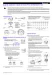
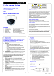
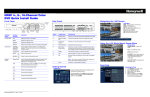
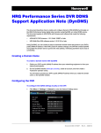
1
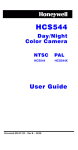
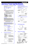
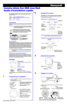
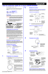
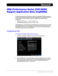
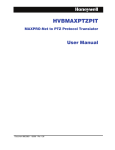
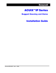
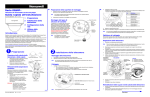
HCS544/HCS544X Camera Quick Install Guide
Installation
Programming
The HCS544/HCS544X camera is designed for general surveillance applications and
is ideally suited for low-light indoor environments.
OSD Menu Controls
Figure 3
Installing the Lens
The HCS544/HCS544X camera is factory configured for a CS-mount lens. Screw the
lens (customer supplied) into the front of the camera body.
Figure 1
Camera OSD control
(4 position plus
center press (ENTER)
Camera Controller
Navigating through the menus
Press this control To do this …
Lens Installation
ENTER (SET)
Press to enter SETUP menu. Press to
enter a screen or select a menu
option.
UP, DOWN
(!, ")
Move vertically between menus and
options.
LEFT, RIGHT
(#, $)
Move horizontally between menus
and options.
ENTER
%
EXIT
Setscrews (x2)
Pin
DC Lens
1
CTRL -
3 4
2
CTRL +
1 2
3
DRV +
4
DRV -
OSD Menu Structure
The HCS544/HCS544X menu system consists of one main SETUP menu (see
Figure 4) for easy camera programming.
Figure 4
1.
Loosen the two setscrews (see Figure 1) with a Phillips screwdrivers.
2.
Adjust the focus ring to focus the picture, then retighten the setscrews.
Menu Structure
Main Menu
The back focus adjustment is accessible at the front end of the camera housing.
1.
Connect the VIDEO connector on the rear of the camera to the video-in connector
on your monitor or video recorder.
2.
Connect the camera to a power supply appropriate for your installation (12 VDC
or 24 VAC).
Plug the power supply into an appropriate power source. The power LED
illuminates to show that the camera is receiving power.
Video Connections
Power LED
Submenu
LENS
Connecting the Camera
Figure 2
Exit the menu.
Note Menu display turns off automatically after 70
seconds of no activity.
Adjusting the Back Focal Length or Picture Focus
3.
Indicates submenus. Select the
menu, then press ENTER.
1
2
3
4
5
6
7
8
9
<<SETUP MENU>>
LENS
DC%
SHUTTER
–––
WHITE BAL.
ATW
BACKLIGHT
OFF
AGC
HIGH%
DNR
MIDDLE
DSS
AUTO
SPECIAL%
EXIT MENU
Menu Options
DC%, MANUAL
SHUTTER
FLK, ESC%, MANUAL
WHITE BAL
ATW, MANUAL%, AWC%
BACKLIGHT
OFF, LOW, MIDDLE, HIGH
AGC
OFF, LOW% , MIDDLE%, HIGH%
DNR
OFF, LOW, MIDDLE, HIGH
DSS
OFF, AUTO%
E
N
T
E
R
See SETUP Menu Functions
for a description of the
submenus and menu options.
+
SPECIAL%
Mounting the Camera
There are mounting points on the top and bottom of the camera to mount the camera
on a bracket or tripod. Use standard sized mounting bolts to install the camera to a
mounting bracket.
Caution Follow local installation codes for proper mounting bracket support
capability.
Top view shown
Mounting point
Making Final Adjustments
Adjust the focus in your field of view until you see a clear image. If necessary, adjust
the brightness using the OSD menu controls (see LENS DC/BRIGHTNESS or AGC).
Confirm the exposure on the monitor screen.
Document 800-01124 – Rev A – 01/08
See SPECIAL Menu.
SPECIAL Menu Functions
SETUP Menu Functions
Menu Item
Option
Description
1
LENS
DC%
MANUAL
Selects lens type.
Press ENTER with DC selected to access the
BRIGHTNESS control for iris level adjustment.
2
SHUTTER
FLK
ESC%
MANUAL
Adjusts shutter settings.
Flickerless mode (FLK) reduces on-screen flickering.
Electronic Shutter Control (ESC) adjusts brightness level
on screen when using a manual lens.
Select Manual mode to adjust the shutter speed from 1/
60-1/120,000 of a second (NTSC), or 1/50-1/120,000
(PAL).
3
4
5
6
Controls color on the screen.
WHITE BAL.
ATW
(White Balance) MANUAL% Select Auto Tracing White Balance (ATW) when the color
AWC%
temp is 1800°K-10500°K (for example when under a
fluorescent light, or outdoors).
Select Manual mode to increase or decrease the red or
blue GAIN on screen.
Select Auto White Balance Control (AWC), then press
ENTER to automatically adjust the white balance to your
specific environment.
BACKLIGHT
OFF
LOW
MIDDLE
HIGH
Provides light level control to overcome severe
backlighting conditions.
AGC
OFF
(Automatic Gain LOW%
MIDDLE%
Control)
HIGH%
Adjusts value of AGC gain.
Increase the GAIN level to brighten the picture in low
light conditions (noise/distortion may develop). The
submenu provides access to the BRIGHTNESS control.
DNR
(Digital Noise
Reduction)
OFF
LOW
MIDDLE
HIGH
Reduces noise/distortion on the screen. Increasing the
DNR level reduces noise but may introduce video
artifacts. DNR is deactivated if AGC is turned off.
OFF
AUTO%
Automatically provides a clear image under low-light
conditions. You can control the maximum low-light
magnification from 2x to 128x (increasing magnification
may cause noise/distortion). DSS is deactivated when
SHUTTER is set to FLK mode.
1
Menu Item
Option
Description
CAMERA ID
OFF
ON
Display a name and/or number on the monitor. To add a
camera title:
CAMERA ID
ABCDEFGHIJKLM
NOPRQSTUVWXYZ
a b c d e f g h i j k l m
n o p q r s t u v w x y z
– . 0 1 2 3 4 5 6 7 8 9
& ( CLR POS END
_______________
2
DAY/NIGHT
AUTO
COLOR
AUTO = Automatically detect color or black/white
COLOR = Full-time color mode.
3
SYNC
INT
L/L
INT = Synchronize the vertical interval sync pulse of
your camera with other equipment to reduce the effect of
picture roll on the monitor.
L/L (Line Lock) = adjust the phase from 0° - 359°.
4
MOTION DET
OFF
ON%
Detect moving objects on screen; displays MOTION
DETECTED when movement is detected. Select the area
on screen you want to observe.
MOTION DETECTION
AREA SEL
AREA STATE
TOP
DOWN
LEFT
RIGHT
AREA 1
ON
|..|................| 10
|........|..........| 25
|...|...............| 20
|........|..........| 40
Press SET to Return
7
DSS
(Digital Slow
Shutter)
8
SPECIAL%
Takes you to the SPECIAL menu (see SPECIAL Menu).
9
EXIT
Exits the SETUP menu and returns to video monitoring.
5
PRIVACY
OFF
ON%
AREA SEL
AREA STATE
AREA TONE
TOP
DOWN
LEFT
RIGHT
SPECIAL Menu
On the SETUP menu, press the menu control UP or DOWN and then select
SPECIAL.
2.
Press the ENTER (SET) control to access the SPECIAL menu.
Figure 5
Press SET to Return
Menu Item Option Description
AREA SEL AREA 1 Select a masking grid (top left, top
AREA 2 right, bottom left, bottom right) to
AREA 3 modify.
AREA 4
AREA
ON
Activate/deactivate the selected grid.
STATE
OFF
Menu Options
CAMERA ID
OFF, ON%
DAY/NIGHT
AUTO, COLOR
SYNC
MOTION DET
PRIVACY
INT (L/L)
OFF, ON%
Press LEFT or RIGHT menu control
left or right to alter the dimensions
of the selected grid.
Mask up to 4 areas of the screen from video monitoring.
AREA
TONE
Submenu
1
2
3
4
5
6
7
8
9
AREA 1
ON
|...............|...| 80
|..|................| 10
|........|..........| 25
|...|...............| 20
|........|..........| 40
SPECIAL Menu
<<SPECIAL MENU>>
CAMERA ID
OFF
DAY/NIGHT
AUTO
SYNC
INT
MOTION DET
OFF
PRIVACY
OFF
MIRROR
OFF
SHARPNESS
ON%
RESET
RETURN%
Menu Item Option Description
AREA SEL AREA 1 Select a motion detection grid (top
AREA 2 left, top right, bottom left, bottom
AREA 3 right) to modify.
AREA 4
AREA
ON
Activate or deactivate the selected
STATE
OFF
grid.
TOP
DOWN
LEFT
RIGHT
PRIVACY
1.
UP, DOWN, LEFT, or RIGHT menu control = select a
character, then press (ENTER) SET to accept it. The
character is saved and the title cursor at the bottom of the
screen moves to the next position.
& ( = go back or forward in the title name to make
changes.
CLR = delete the entire name and start again.
POS = position the camera title on the screen. Press
(ENTER) SET to confirm the position.
END = accept the new name.
TOP
DOWN
LEFT
RIGHT
Press LEFT or RIGHT menu control
to change the shade of the masking
grids.
Press LEFT or RIGHT menu control
to alter the dimensions of the
selected grid.
6
MIRROR
OFF
ON
Produce a horizontal mirror image on screen.
7
SHARPNESS
ON%
OFF
Sharpen the image on screen (image level 0 - 31).
Excessive sharpening may cause picture noise.
8
RESET
Restore all factory default settings.
9
RETURN%
Return to the main SETUP menu.
OFF, ON%
MIRROR
OFF, ON
SHARPNESS
ON%, OFF
RESET
www.honeywellvideo.com
+1.800.796.CCTV (North America only)
[email protected]
Document 800-01124 – Rev A – 01/08
© 2008 Honeywell International Inc. All rights reserved. No part of this publication may be reproduced by any means without written permission from Honeywell Video Systems. The information in this publication is believed to be accurate in
all respects. However, Honeywell Video Systems cannot assume responsibility for any consequences resulting from the use thereof. The information contained herein is subject to change without notice. Revisions or new editions to this
publication may be issued to incorporate such changes.