1
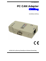
Users Manual for
PC CAN Adapter
CANKey
Installation and Setup
2004-2011 by Dipl.-Ing. Ewald Sperrer Software-Entwicklung
License agreement
By the purchase of the CANKey adapter, the buyer or user of this product does not
obtain any copyrights, patent rights or duplication rights on this product and on any
accompanying accessories (including software and documentation).
Software that is part of this product as well as this documentation may be passed to
others only in its original condition. When passing this product to others, all parts of
it (including this manual) has to be included. All rights (software and documentation)
remains in any case with the author. The sale and commercial use of this software
and documentation without written permission of the author is prohibited.
The use of the software contained or supplied with this product (either stored on data
media or programmed in CPU’s) is only allowed in conjunction with the product
itself.
Note
This manual as well as the hardware module CANKey (also called "adapter") was
produced with great care. Should you have any comments, corrections or suggestions
to the manual or the adapter, please forward them to the address given below.
When operating this unit, please follow the relevant safety rules. No guarrantee or
restitution for damage or subsequent damage caused by this product will be made.
The use of this product is done at one's own risk. Any warranty will be void if this
manual isn’t strictly followed.
We cannot guarrantee that this module works with every hardware and software
combination due to the large number of possibilities. After inspecting this product,
you as end user or licensee respectivly, will accept it „as is“. Nevertheless the manufacturer grants a two years limited warranty for the adapter and the data media for
parts and labour starting with the purchase date. Any deficiencies that do not reduce
the suitability or usability of this product remain out of scope of this warranty. The
manufacturer is liable only for errors due to gross negligence or intent. In any case
the liability is limited to the value of the product itself.
The manufacturer reserves the right to change the product as well as the accompanying software and documentation at any time and to deliver modified products.
Revisions
First edition:
First english version:
First revision:
Second revision:
Third revision:
V1.0, November 2004
V1.0, March 2005
V1.1, November 2006
V1.2, April 2007
V1.3, January 2011
Author
Dipl.-Ing. Ewald Sperrer
Software-Entwicklung
Weißenberg 23
A-4053 HAID / ÖSTERREICH
Trademarks
„WINDOWS“, „MS-WINDOWS“, "Vista" and „MS-DOS“ are brand names of
Microsoft Corp. All other product or company names are brand names or copyright
protected by the respective manufacturer
Copyright
2004-2011 by E. Sperrer. All rights reserved. The copying of this documentation
or the software integrated into or delivered with the product for commercial use
without written permission of the author is prohibited.
Contents
1. General Notes ................................................................................................................................................3
1.1. Safety instructions.................................................................................................................................................... 3
1.2. Functionality of the adapter ..................................................................................................................................... 3
1.3. Areas of usage .......................................................................................................................................................... 4
1.4. Prerequisites ............................................................................................................................................................. 4
1.5. Package contents ...................................................................................................................................................... 5
2. Setup for Operation.......................................................................................................................................7
2.1. Connectors and indicators ........................................................................................................................................ 7
2.2. PC connection via USB............................................................................................................................................ 8
2.3. PC connection via RS-232 ..................................................................................................................................... 12
2.4. First-time operation, test using CANfigurator........................................................................................................ 13
2.5. Integration with STP .............................................................................................................................................. 15
2.6. Problem survival guide .......................................................................................................................................... 16
3. Addendum....................................................................................................................................................19
3.1. Technical specifications ......................................................................................................................................... 19
3.2. Data transmission protocol..................................................................................................................................... 20
3.3. Operating environment........................................................................................................................................... 22
3.4. Limited warranty conditions .................................................................................................................................. 22
4. Index .............................................................................................................................................................23
User manual for PC-CAN adapter CANKey
Contents • i
This page was left blank intentionally.
ii • Contents
User manual for PC-CAN adapter CANKey
1. General Notes
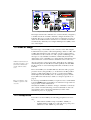
1.1. Safety instructions
For other countries their
respective regulations and
safety guidelines apply.
When working with products that can come in contact with electric voltage, the applicable safety regulations have to be obeyed. For Austria
these are in particular VDE 0100, VDE 0550/0551, VDE 0700, VDE
0711 and VDE 0860 resp.. ÖVE EN-1, ÖVE E 8001, ÖVE EN 60 742.
Please keep this instruction manual in a safe place for future reference. If
you hand over this CANKey (also called "adapter" in the following context) to other persons, make sure to include this manual.
Additionally please note the following safety guidelines:
•
Only use the module for the purpose for which it is intended
and check that it has been installed correctly. If in doubt,
consult a professional, expert or ask the manufacturer of the
adapter.
•
Operation of the adapter is only admissable in the supplied
case. The adapter is not suitable for open-air operation.
•
Examine all external wiring before attaching for breaks or insulation failure. Repair all defects immediately before connecting
to the adaptor.
•
Opening of the adapter is only admissable for trained experts
with appropriate specialized knowledge. Opening the adaptor
by the use will void the waranty.
•
When setting up electronic components, install them according
to the specifications given in the manual supplied with the
equipment.
•
Please note that operation or connection errors are out of our
scope of influence and we cannot take over any liability for
resulting damages.
•
All semiconductors, especially ICs, are susceptible to static discharge. Make sure your body is not electrically charged by touching a metal body first (e.g. a copper water pipe). Wearing a
ground strap or working on a ground mat is highly recommended.
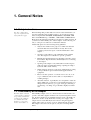
1.2. Functionality of the adapter
The Zimo digital command
control system is equipment
for operating a model railroad. It uses the CAN bus
for communication with
throttles, accessory and
track section modules etc.
The CANKey adapter serves as connection between a PC and the components of the Zimo digital command control system using Zimo's CAN
bus. It can be attached to any usual PC using the serial or the USB port
(USB V1.1, V2.0 or V3.0). In the first case the power supply of the
adapter is done via the PC's keyboard connector using the supplied
splitter cable, in the second case power is obtained directly from USB.
The adapter is the same for both options, only the connecting cables
differ.
User manual for PC-CAN adapter CANKey
General Notes • 3
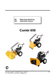
Fig. 1: Context of the CANKey adapter in the Zimo DCC system
The adapter transfers all commands sent over the CAN bus ("telegrams")
to the PC and can also transmit commands coming from the PC to the
CAN bus. The proper operation of the device as well as the reception of
data from the CAN bus and the transmission of commands from the PC
are indicated by differently colored light emmiting diodes (LEDs) on the
case of the adapter.
1.3. Areas of usage
The main usage of the CANKey is the connection of the Zimo Digital
Command Control system to railroad dispatching software on a PC, such
as STP. Although the base unit of the Zimo system is equipped with a
serial interface for the connection to a PC, specific command types and
messages are only available via CAN bus. Additionally the CAN bus
data transfer speed of 125 kBit / sec is faster than the serial interface and
data transmission over the CAN bus is handled in a more secure way.
Additional information for
the CSA-32 modules can be
found in the STP manual
and the CSA-32 instructions.
Also the connection of CSA-32 modules, which allow (in conjunction
with the lamp driver module PLV-32 and the pushbutton module PTP64) the connection of an external dispatcher table, is handled over the
CAN bus.
Before the CANKey was avaialble STP was delivered with a program
protection device ("Program Key"), to be attached to the PCs parallel
printer port. This functionality is now also covered by the CANKey,
which implies that the CANKey has to be attached properly to the PC
before STP can be activated (for details see "Setup for Operation" on
page 7).
Ther serial number of the
CANKey is printed on the
enclosure.
For the usage with STP the CANKey is required to have a serial number
lower than 9500, higher serial numbers are intented for usage with software products of other manufacturers.
Generally the CANKey is suitable to all types of CAN bus connectivity
(also outside of model railroading). A brief documentation of the software interface can be found in the addendum (see under "Data
transmission protocol" on page 20).
1.4. Prerequisites
To be able to use the CANKey, the following prerequisites are necessary:
•
4 • General Notes
A PC with an available serial port (COM1: - COM4:) or
available USB port (USB V1.1 / 2.0 / 3.0, a low-power port is
sufficient, i.e. max. 100mA of power drain)
User manual for PC-CAN adapter CANKey
•
PS/2 keyboard connector (when attaching the CANKey via
serial port)
•
Windows ME, NT1), 2000, XP2), Vista2) or Windows 72)
•
CD-ROM or DVD drive
•
STP release 5.06 or higher or another software product with
CANKey support (for Windows Vista STP V5.11 or higher, for
Windows 7 or any 64 bit operating system STP 5.19 or higher)
•
6-pole Zimo CAN bus interface cable (with Western plugs)
1)
This operating systems need special drivers to be able to connect USB
equipment to the PC which are not part of this delivery. An operation of
the CANKey under Windows 95 and Windows 98 is not intended.
2)
These operating systems are supported in their 32- and 64-bit editions.
Note that 64-bit support is a new feature and has not yet been tested
under all circumstances.
1.5. Package contents
The CANKey adapter is delivered as fully assembled module with the
following accessories (depending on the module type):
Count
Description
Remark
1
CANKey adapter
1
Power supply cable
only for serial version
1
USB connection cable (2 x
plug type "A")
only for USB version
1
STP update CD or driver CD contains the driver software and a
(depending on the order)
test program
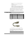
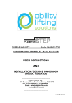
For easier identification of the items here an image of the supplied connection cables:
Fig. 2: Power supply connector for operation via serial PC port (RS-232)
The power supply cable is only necessary if the CANKey is attached to
the serial interface (COMx:) of the PC. It will be inserted between the
keyboard plug and the PS/2 keyboard connector of the PC. If the PC
employs a DIN socket for the keyboard connection, an adapter has to
used (not included).
Note: The USB plug of the power supply cable only serves to provide
electrical power to the module, it furnishes no USB data connection!
User manual for PC-CAN adapter CANKey
General Notes • 5
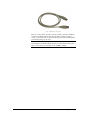
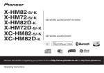
Fig. 3: USB connection cable
Please note also that no specific connection cable to the Zimo CAN bus
is delivered with the adapter. The standard Zimo CAN bus cables as
used to connect the Zimo components among each other (featuring the 6pole Western plug) can be used.
Note: The connection cable for the attachment of the Zimo system to
CAN adapters produced by Peak System (as featured in the Zimo price
list) is not necessary nor suitable for the CANKey adapter.
6 • General Notes
User manual for PC-CAN adapter CANKey
2. Setup for Operation
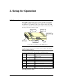
2.1. Connectors and indicators
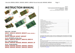
The CANKey adapter features three connectors and three visual indicators (LEDs). On the front side there is the connector for the serial interface (RS-232, 9-pole SUB-D socket), on the sidepiece there is the USB
connector (type A) and on the back side the connector for the Zimo CAN
bus (6-pole Western socket) is located.
Status and
error LED
Data reception
from PC
Zimo CAN bus
RS-232
Data reception
from CAN bus
USB
Fig. 4: Connectors and indicators of the CANKey adapter
Note: The adapter can only by attached to either a serial or an USB port
of a PC. If both connections are available on the computer, the USB interface should be preferred.
On the top side of the adapter, three light emitting diodes (LEDs) are
present to indicate its state. They have the following meaning:
Color Type
Meaning
red
blinking (>10 / sec)
Adapter is waiting for interface selection
(USB or serial)
blinking (1 / sec)
Adapter ready, CAN bus comm. deactivated
blinking (3-4 / sec)
Adapter ready, CAN bus comm. activated
steady
Error state
off
Error state
yellow
blinking
Data received from PC
yellow
steady
Error state
green
blinking
Data received via CAN bus
The following chapter will explain the connection options using serial
and USB port in more detail.
User manual for PC-CAN adapter CANKey
Setup for Operation • 7
2.2. PC connection via USB
This is the preferred method of attaching the adapter to the PC. Only if
your PC has no (available) USB port, the serial interface option should
be chosen (see "PC connection via RS-232" on page 12).
If the so-called "Sleep mode" is activated on the PC,
problems may arise when
attaching or detatching the
adapter (see "Problem
survival guide" on page 16).
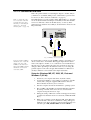
The USB interface provides a feature called "Plug & Play", i.e. the adapter can be attached without shutting down the PC (for first time installation we recommend to shut down the PC anyway, see below). If the
adapter has been attached successfully, it should remain connected to the
PC permanently.
LPT1:
USB
COM1: COM2:
Fig. 5: CANKey connection via USB
It does not matter if STP is
installed before or after the
initial connection of the
CANKey to the PC. Nevertheless the CANKey must be
installed before the first
activation of STP.
For the first time connection of the CANKey adapter to the USB port, a
driver software has to be installed. This happens right after the attachment of the adapter to the PC, i.e. no software has to be installed before
this action. To do this, simply follow the steps given below (the setup
dialogues differ depending on the Windows version you are using, the
general sequence is the same, though). The installation for Windows 7
(64 bit) is different, it is described in the chapter afterwards.
Setup for Windows ME, NT, 2000, XP, Vista and
Windows 7 (32 bit)
8 • Setup for Operation
1.
Shut down your computer and turn it off (mains switch)
2.
Connect the CANKey to a free USB port of the PC or an USB
switch ("hub") using the supplied USB interface cable; the
Zimo CAN bus should not yet be connected
3.
Start the computer and activate the Windows operating system
4.
The red LED of the CANKey should start flickering right after
the startup of the PC; if this is not the case, shut down the
computer and repeat the last two steps
5.
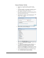
During the startup of Windows a window will appear and notify
you that a new hardware device was detected ("STP USB CANKey")
6.
With some operatings systems (Windows XP, Vista, Windows
7) if an internet connection is established, a dialog will appear,
asking if a new driver should be loaded via internet. In this case
select the option No, not this time and click at Next >.
User manual for PC-CAN adapter CANKey
7.
Now insert the setup-CD of your software product (i.e. the STP
installation or update CD) into your CD / DVD drive and click
at Next (possibly the installation process will continue automatically after the CD has been inserted); in case no proper driver
has been detected, enter X:\ as installation path (X: should
reflect the drive letter of your CD-ROM / DVD drive)
8.
If Windows XP, Vista or Windows 7 is used, a note about an
unverified driver will be shown; this is OK, so click at
Continue Anyway.
9.
After some time a message about the end of the installation process will be shown; click at Finish
10. On some Windows versions a message will be displayed that
the new device can be used now
11. When newer Windows versions are used (XP, Vista, 7) now a
second new device will have to be installed ("Serial USB driver"), so the steps 6 – 10 have to be repeated (step 7 is skipped
as the CD has laready been inserted)
12. Now the Zimo CAN bus can be attached by inserting the Western plug of the CAN bus cable into the proper socket of the
adapter.
User manual for PC-CAN adapter CANKey
Setup for Operation • 9
Setup for Windows 7 (64 bit)
10 • Setup for Operation
1.
Shut down your computer and turn it off (mains switch)
2.
Switch on the computer and start the Windows operating
system
3.
Connect the CANKey to a free USB port of the PC or an USB
switch ("hub") using the supplied USB interface cable; the
Zimo CAN bus should not yet be connected
4.
The red LED of the CANKey should start flickering right after
the startup of the PC; if this is not the case, shut down the computer and repeat the last three steps
5.
A window appears notifying of a newly detected device ("STP
USB CANKey") for which no driver software has been
installed – click on Close
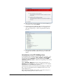
6.
Open the Windows Device Manager (Start / Control Panel /
Hardware and Sound / Device Manager)
7.
Click on the STP USB CANKey entry using the right mouse
button and select Update Driver Software… from the menu
which will appear
8.
Select Browse my computer for driver software in the
next window, select your CD / DVD drive letter in the
following window, insert the setup CD of your software
product (i.e. the STP installation or update CD) into your CD /
DVD drive and click at Next (if the STP installation procedure
should be starting in the background you can simply close it)
9.
A note will appear that the driver to be installed is not signed.
Click at Install this driver software anyway
User manual for PC-CAN adapter CANKey
10. After some time a message about the end of the installation process will be shown; click at Close
11. The Windows Device Manager will now show a second new
device ("USB Serial Port") which has to be installed in the
same way (repeat steps 7 – 10, for step 8 the CD is already
inserted)
12. Now the Zimo CAN bus can be attached by inserting the Western plug of the CAN bus cable into the proper socket of the
adapter.
Unistallation of the STP CANKey driver
To uninstall the driver (which normally should not be necessary), open
the software inventory of the PC (Start / Settings / Control panel
and then click at the Software icon) and look for the entry FTDI
FTD2XX xxx Drivers (xxx is a different text depending on the current
driver version).
Click at Change / Remove and in the window that will appear, at
Continue and then Finish. Note that the CANKey has to be detached
from the PC before performing this operation.
Alternatively the driver can be removed by uninstalling the "STP CANKey" device from the Windows Device Manager (under "Ports" and
under "USB devices").
When attaching the CANKey the next time, a new driver setup according to the procedure given above has to be done.
User manual for PC-CAN adapter CANKey
Setup for Operation • 11
The verify the functionality of the CANKey, please follow the steps
given under "First-time operation, test using CANfigurator" on page 13.
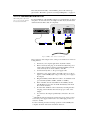
2.3. PC connection via RS-232
When using this connection
type, no sleep mode should
be activated on the PC.
For the installation of the CANKey adapter to a serial interface no driver
setup has to be done. However, the adapter should only by attached and
detached when the PC is shut off completely.
LPT1:
USB
COM1: COM2:
Fig. 6: CANKey connection via serial PC port
The connection of the adapter to the seriel port should be done in the following manner:
1.
Shut down your computer and turn it off (mains switch)
2.
Remove the keyboard plug*) from the PC and attach the power
supply cable (which was delivered with the CANKey) instead
of it to the keyboard connector (PS/2) of the PC
3.
Connect the keyboard*) to the power supply cable
4.
Attach the power supply cable to the USB connector on the sidepiece of the CANKey (this only provides the power supply to
the adapter)
5.
Plug the CANKey with its RS-232 socket to an available serial
port of the PC (COM1:, COM2:, COM3: or COM4:)
6.
Turn on the PC; the red status LED on the CANKey should
start flickering (if not, turn off the PC immediately and check
the connection cables)
7.
Now the Zimo CAN bus can be attached by inserting the Western plug of the CAN bus cable into the proper socket of the
adapter
8.
You can leave the adapter permanently connected to the computer.
*)
Alternatively instead of the keyboard also the mouse can be connected via the power supply cable if it also uses a PS/2 plug for the connection to the PC.
For all connecting and disconnecting operations of the CANKey the
computer should be shut down and turned off before.
12 • Setup for Operation
User manual for PC-CAN adapter CANKey
2.4. First-time operation, test using CANfigurator
If the CANKey is to be used
with another software
product than STP the following steps may be different.
After successful connection of the CANKey to a serial or a USB port you
should check if the adapter works as intended. For this purpose the
CANfigurator software has been installed together with your model
railroad control software.
If you should have ordered
the CANKey together with
STP or as supplement to an
already existing STP version, a STP setup CD is
included with the CANKey.
If you should not have STP already installed on your computer or the
version you are using is earlier than STP V5.06, please now insert the
STP setup CD into the optical drive of your PC and install the software.
Instructions for the installation will be shown on-screen or can be found
in the STP manual.
Important note: Because two programs are not allowed to access the
CANKey simultaneously, the model railroad control software and the
CANfigurator software cannot be active at the same time.
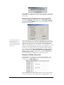
If you then start the CANfigurator program (when using STP this is:
Start | Programs | STP | CANfigurator) the following window will
be shown:
Detection of the CAN adapter
First you should allow the program to detect any attached CAN adapter
automatically. Click at the button Find CAN Adapter... and wait until
the adapter is detected. This auto-detection functionality also works for
CAN adapters from Peak System (except for the Peak ISA card). You
may interrupt the detection process anytime by clicking at the Close
button.
After successful detection, the adapter type along with version information of the firmware as well as the driver will be shown.
User manual for PC-CAN adapter CANKey
Setup for Operation • 13
Click at OK to close this window. If the adapter was not recognized automatically, the configuration can also be done manually as described in
the next step.
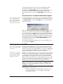
Saving of the configuration for usage with STP
Now open the Options dialog window by selecting Tools | Options...
from the menu. In the Options window the detected adapter type will
already be pre-selected.
The PCAN ISA adapter by
Peak System has to be configured manually in any
case because an auto-detection is not possible for this
adapter type.
If the adapter has not been detected automatically in the previous step,
you now can select the proper adapter type manually. Depending on this
adapter type it may be necessary to enter additional information at the
right side of the window (e.g. for the serially connected CANKey the
number of the COM port has to be entered, i.e. 1 for COM1: etc.) – if the
detection was done automatically, this information is already present.
To take over the settings shown here into the CAN adapter configuration of STP, click at the Save configuration button. When doing so,
there is no need for the CAN adapter setup in STP (Configuration |
Global interface setup...). The options shown here will then also be
present again when the CANfigurator is started the next time.
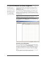
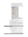
Display of CAN bus data traffic
The CANfigurator also allows you to monitor the data traffic on the
CAN bus. To do so, click (with properly configured adapter, see previous steps) at the Open CAN button.
After that all CAN bus data telegrams which are sent on the bus will be
shown in the right part of the program window (including their corres-
14 • Setup for Operation
User manual for PC-CAN adapter CANKey
ponding time stamp). The list will store the last 100 data telegrams.
Using the scrollbar at the right you can browse through the list.
By clicking on the Close CAN button, the protocol feature will be disabled - the recently received information will still remain visiblethough. The list will be cleared when Open CAN is activated the next
time.
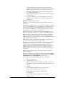
Transmission of user-defined CAN data telegrams
Only use this function when
you are familiar with the
internas of the Zimo CAN
bus or you have detailled
instructions what to do (e.g.
from the CSA-32 manual).
To send data telegrams of your own (e.g. for testing and parametrization
of CSA-32 modules), the CAN adapter must be accessible (see previous
step, Open CAN). Now click at the Send button to open the dialogue
window shown below:
Enter the CAN telegram ID under ID and under Len the number of data
bytes (0-8) to be transmitted. In the data entry fields after Data the values for each byte of the telegram have to be entered (all in hexadecimal
notation). By clicking on Send!, a CAN telegram with the given information will be transmitted. Telegrams that have been sent will be shown
in a blue font in the protocol list (see previous step). The protocol functions remain active also when the Send CAN Telegram window is
present in the foreground.
If no further CAN telegram should be sent, close the transmission window by clicking on Cancel.
2.5. Integration with STP
STP can also be started with
the previously supplied STP
Program Key.
Because the STP CANKey is also used for license verification, it has to
be installed and operational before STP can be started (see also under
"First-time operation, test using CANfigurator" on page 13). STP checks
during program start if the CANKey is present and will show an error
message ("Program Key not detected") if this is not the case.
This step may be omitted if
the setup of the CANKey has
been done using the CANfigurator software and the
result has been saved.
STP has to be configured properly to access the CANKey at all. If STP is
installed from scratch and the CANKey is attached to the USB port, this
is not a problem, because this matches with the defaults of STP after a
fresh installation. If an update from a previous version has been made,
STP should first be started with the "old" Program Key (as before). After
proper setup (explained below) and saving of the configuration, the Program Key can be removed (the PC should be shut down before).
Important nore for a fresh installation of STP: When the CANKey is
attached to a serial PC port (i.e. not using USB), you must set up the
CANKey before using the CANfigurator software (see "Saving of the
configuration" on page 14).
To configure an already existing / updated version of STP for usage of
the CANKey, proceed as follows:
1.
Install the CANKey in an availabe USB or serial port of your
PC (see previous chapter) – the red LED on the CANKey
should flicker rapidly
User manual for PC-CAN adapter CANKey
Setup for Operation • 15
2.
Install the new STP version delivered with the CANKey (if
newer than your current version and if you have not done so
yet) - the CANKey is supported from STP V5.06 upward.
3.
Start the newly installed STP version (do not forget that the
STP Program Key should also be left attached)
4.
Open the Global Interface Setup dialog window (Configuration | Global interface setup...)
5.
Under CAN-Bus Interface select the STP CANKey entry
and on the right the port to which the adapter is connected
(USB, COM1:, COM2:, COM3: or COM4:)
6.
Click at Save.
If you previously have used the Program Key, you may remove it after
the next shut down of the computer. Note that now the CANKey has to
be attached to the PC before STP can be started.
To test if the adapter is working properly under STP, activate STP's online mode (Control | Online). The red LED on the adapter now should
blink with a frequency of 3-4 times / sec (this is slower than when the
adapter is just attached to the PC). When data from the CAN bus is received, the green LED should blink, when data from the PC is sent, the
yellow LED should blink. When the online mode is deactivated, the red
LED should blink with a very low frequency (1x / sec).
2.6. Problem survival guide
If the adapter does not work as expected, here some tips to make the
location of troubles somewhat easier:
If the red LED does not light up (flash) when powering up the adapter,
detach the adapter from the PC immediately, shut down the PC, turn it
off and execute the following checks:
16 • Setup for Operation
•
Is the module correctly connected to the PC (see "PC
connection via USB" on page 8 resp. "PC connection via RS232" on page 12)?
•
When connecting the adapter via USB it is possible that the
CANKey does not always start up correctly (i.e. all LEDs
remain dark, but an acoustical sign reports that an USB device
User manual for PC-CAN adapter CANKey
has been attached to the computer); in this case detach the
adapter from the PC, wait 3 seconds and then re-attach it again
(the computer does not have to be shut down in this case)
•
Is the Zimo CAN bus disconnected from the adapter when doing a first-time installation?
•
If connecting the adapter to an USB hub: Is the power supply of
the hub turned on?
•
Does the problem also occur, if the adapter is connected to a
different port (i.e. COM1: instead of USB, COM2: instead of
COM1: etc.)?
F.A.Q. (Frequently Asked Questions):
F: STP does not start and the message ""Program Key not detected"
comes up.
A: Check if the CANKey adapter is connected and working properly. If
yes, try to start STP with an "old" Program Key (if available) and follow
the steps given in chapter "Integration with STP" on page 15. If you
have connected the CANKey to a serial port using an extension cable,
check if all 9 wires of the cable are connected 1:1.
F: After powering up the adapter for the first time, the LED does not
flash, but is constantly on and /or the yellow or green LED is lit / blinks
A: Shut down the computer and disconnect the module. Check all connections and restart the computer. Remove (on a trial basis) the Zimo
CAN bus cable. If the problem persists, contact the manufacturer with an
exact explanation of the problem.
F: The adapter seems to work properly (according to the LED indicators), but no data is transmitted over the CAN bus.
A: Check if the CAN bus cable to the Zimo system is attached properly
and that it shows no defects. Shut down the computer and the Zimo
system and restart both (without attaching the CAN bus cable to the
CANKey). Attach the CAN cable just before activating Online mode in
STP. It could also be necessary to remove the "ground" connection
within the the CAN cable to the adapter (see "Technical specifications"
on page 19).
F: When starting STP I get an error message that the "Program Key"
cannot be detected.
A: Start the CANfigurator program and set the options for the CANKey
properly (or do an automatical adapter recognition). Then click at Save
configuration in the Tools | Options... dialog window.
For persistent errors the following procedure is recommended:
•
Switch off computer
•
Switch off Zimo system
•
Remove connection between CANKey and Zimo system (i.e.
the CANKey remains connected to the PC via the USB or serial
cable)
•
Start PC
•
The red LED should blink now in a quick sequence
•
Attach CAN cable from the Zimo system
•
The red LED should continue to blink quickly
•
Start up STP
•
The red LED should now blink in a slower manner
•
STP has started
User manual for PC-CAN adapter CANKey
Setup for Operation • 17
•
Switch on the Zimo system
•
The red LED should continue to blink in a slow manner
•
Activate STP Online - mode
F: When my PC restarts from sleep mode, the CANKey does no longer
operate properly / there are problems when putting the PC into sleep
mode. What can I do?
A: Unfortunately some computer / operating system combinations have
problems putting USB devices into sleep mode properly or restarting
them after sleep mode. If this problem should appear on your system it
normally is best to deactivate sleep mode completely in the Windows
System Management (at least while using the PC for model railroad
control). If the CANKey does not "awake" correctly after sleep mode, it
should be sufficient to unplug the adapter for a short period and to reconnect it again. Please note that the CANKey will be uninitialized after
sleep mode, so if Online mode was active before entering sleep mode,
the Online mode has to be stopped and re-entered after awaking from
sleep mode, because otherwise the CAN bus communication will not
work properly. It is recommended not to put the PC in sleep mode while
STP Online mode is active.
F: When attaching the Zimo CAN bus cable to the CANKey, the red
status LED goes off and the CANKey cannot be accessed any more.
A: The CANKey is susceptible to static electricity, ground loops and
voltage differences between PC and digital command system. Unplug
the CANKey from the power supply in this case (remove the plug from
the USB socket of the adapter and re-insert it again). The red LED
should start flickering again (if not, repeat the process). If the problem
should appear more frequently, it is recommended to start up the digital
command system before turning on the PC and to establish the connection PC – CANKey and CANKey – Zimo CAN bus before switching on
these systems.
18 • Setup for Operation
User manual for PC-CAN adapter CANKey
3. Addendum
3.1. Technical specifications
Adapter dimensions:
approx. 80 x 42 x 20 mm ( 1/4" x 1/8"
x 13/16") (without socket extensions,
else 85 x 50 mm)
Supply voltage:
5V DC (via USB or PC keyboard
connector)
Power consumption:
90mA, 400uA in sleep mode
Ambient temperature:
0 – 60 °C (32 °F –140 °F)
Max. rel. humidity:
85 %
PIC controller:
Microchip PIC18F248
CAN line driver:
PCA82C250 (or 82C251)
Serial line driver:
ICL3222
Clock frequency controller:
32 MHz (8 Mhz Quartz x 4, PLL HS4)
USB interface chip:
FTDI FT232BM
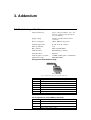
Pin layout for Zimo CAN bus plug:
Pin: 1 2 3 4 5 6
Fig. 7: Pin layout for Western plug (Zimo CAN bus)
Pin
Assignment
1
Power supply from base unit (approx. 40V) *)
2
Ground shield *)
3
CAN_L
4
CAN_H
5
Ground
6
SS signal (for old Zimo data format) *)
*)
Pin not connected inside of CANKey adapter
Pin assignment of serial CANKey connector:
Pin
CANKey assignment
2
RxD, serial data reception
3
TxD, serial data transmission
4
DTR, Data Terminal Ready, PC notifies CANKey to use the
serial interface (and not USB)
User manual for PC-CAN adapter CANKey
Addendum • 19
serial interface (and not USB)
5
GND, ground
7
RTS, Request To Send, data synchronisation line
8
CTS, Clear To Send, data synchronisation line
Important: To indicate the CANKey whether to use the USB or the
serial interface, the PC has to set the DTR line (pin 4) to logical "1" if
the data transmission should be done using the serial connection (RS232).
Pin layout for CANKey USB connector
Pin
Assignment
1 (left, i.e. facing toward the RS-232 conn.)
+5V supply
2
Data -
3
Data +
4
Ground
The power supply cable, which is used when connecting the CANKey to
the serial port (RS-232) of the PC, gets the +5V supply and ground from
the keyboard feed and connects it to pin 1 and 4 of the USB connector
(see also "PC connection via RS-232" on page 12).
3.2. Data transmission protocol
All data telegrams (with the exception of the initialization telgram) have
the structure
<command byte> [<data byte>...]
where the command byte can be recognized by a hexadecimal "2" in the
upper half byte. Data bytes must not contain command bytes, so all data
bytes in the range 0x20 ... 0x2F are prefixed by an 0x2E byte ("escape")
and the 5th bit of the data byte will be set to 0. After reception the 0x2E
byte is removed and the 5th bit will be set again. The 0x2E byte is not
considered for all length calculations. Note: For data sent from the CANKey to the PC this is only true for CAN data telegrams, not for other
answers to the PC.
The data communication is initiated from the PC (i.e. the PC sends, the
CANKey answers), except for received CAN telegrams in Online mode,
(in this mode the CANKey sends every received telegram to the PC immediately) and after a reset of the CANKey (the adapter then sends an
INIT request to the PC).
Online mode (CAN active)
PC sends:
2E 2E 2E 2E 2A <BR> Initialization, BR = divisor for CAN baud rate
(0x10 = 125 kBit/sec, 0x08 = 250 kBit/sec, ...
0x00 and 0xFF are not allowed)
CANKey answers:
2A
Online mode (CAN communication is active);
this message will also be sent if the adapter
has been in Online mode before
2F
Unrecognized command, protocol error
Offline mode (CAN inactive)
PC sends:
2A 00
20 • Addendum
User manual for PC-CAN adapter CANKey
CANKey answers:
29
CANKey is now in Offline mode, i.e. no more
data is send to the PC spontaneously
2F
Unrecognized command, protocol error
Status request
PC sends:
2A FF
CANKey answers:
2A
Online mode (CAN communication active)
29
Offline mode (CAN communication inactive)
2F
Unrecognized command, protocol error
Send CAN telegram (only in Online mode)
PC sends:
2<x> <IDH> <IDL> [<D0>...] <x>: Length of the remaining bytes (0 8) without ID.
<IDH>, <IDL>: High byte (bit 11.. 8) and
low Byte (bit 7..0) of the CAN Id.
<D0>: data byte 0, <D1..7>: data byte 1 .. 7
Ex.: CAN telegram ID=78, D0=12, D2=34
PC command: 24 00 78 12 34
CANKey answers:
2F
Command not recognized (serial overflow), or
unable to send CAN command even after retry
(8x)
29
CAN command has been sent
CAN telegram received (only in Online mode, spontaneous)
CANKey sends:
2<x> <IDH> <IDL> [<D0>...] <x>: Length of the remaining bytes (0 8) without ID.
<IDH>, <IDL>: High byte (bit 11.. 8) and
low Byte (bit 7..0) of the CAN Id.
<D0>: data byte 0, <D1..7>: data byte 1 .. 7
Ex.: CAN telegram ID=123, D0=00
PC command: 23 01 23 00
2C
CAN overflow, telegrams have been lost
Init-request from CANKey (only in Online mode, spontan.)
CANKey sends:
2E 2E 2E 2E
Initialization request
PC answers:
2A <BR>
Initialization, BR = divisor for CAN baudrate
(0x10 = 125 kBit / sec, 0x08 = 250 kBit / sec, ...
0x00 und 0xFF are not allowed)
CANKey answers:
2A
Online mode (CAN communication active);
this message will also be sent if the adapter
has been in online-Mode before
2F
Unrecognized command, protocol error
User manual for PC-CAN adapter CANKey
Addendum • 21
3.3. Operating environment
When operating the CANKey the following conditions and prerequisites
should be observed:
•
An outdoor operation or operation in humid environment is not
allowed.
•
Contact with splashing water or other liquids has to be avoided.
•
The adaptor should not be used in an environment containing
combustible gases or fumes.
•
If the adapter has been in contact with moisture (i.e. condensed
water), after drying it has to be checked by a qualified technician before it can be operated again.
•
When operating the adapter, the nominal voltage ranges for the
power supply as well as for input and output signal levels have
to be adhered to.
•
The ambient temperature must be in the range of 0° to 40° C
(32 °F –100 °F)
•
Operation of the adapter by a minor has to be supervised by an
knowledged adult or a technician.
Please note that by not obeying these notes the implied limited warranty
for the product will be void.
3.4. Limited warranty conditions
We provide a limited warranty for this product for two years. The warranty includes remedying of faults which can be unambiguously attributed to faulty material or production faults.We guarantee an operation
of the adapter according to its characteristic quantities when installation
as well as operation of the adapter is done according to the rules given in
this instruction booklet.
Additional claims are excluded. We do not assume any liability in excess
to legal rules given by the national legislation. We reserve to do a repair,
improvement, substitute delivery or refund of the payment.
The right to claim under guarantee is void under the following conditions:
22 • Addendum
•
for damages caused by non-obeying the instructions or the connection plan,
•
when modifying or attempting to repair the adapter,
•
when unauthorizedly changing the circuitry,
•
for damages caused by overload of the adapter,
•
when connecting the adapter to invalid voltage levels or current
types or to unintendted interface ports (even if they allow a
mechanical and electrical connection with the adapter),
•
for damages caused by manipulation from third parties,
•
for invalid operation or damages caused by negligence or
misuse,
•
for damages caused by electrostatic discharge when touching
parts of the adapter.
User manual for PC-CAN adapter CANKey
Windows XP 9
Z
Zimo 3–9, 12, 15, 17–19
4. Index
A
accessory 3
assignment 12–15
C
CANfigurator 17
configuration 14–17
connection cable 5–6, 12
connector 3–5, 7, 12, 19–20
CSA-32 4, 15
D
data traffic 14
detection 13
driver 4–5, 8–11, 13, 19
K
keyboard connector 3–5, 12
L
LED 8, 10, 12, 15–18
P
plug 3–5, 7, 12, 19–20
power supply 3–5, 12, 17–20
power supply cable 5, 12, 20
Program Key 15–17
S
setup 7–16, 7–16
sleep mode 8, 12, 18–19
software 4–5, 8–11, 13, 15
STP 4–5, 8
U
uninstall 11
W
warranty 22
Western plug 5–6, 9, 11, 12, 19
User manual for PC-CAN adapter CANKey
Index • 23