1
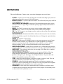
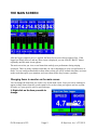
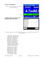
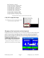
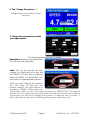
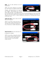
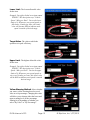
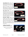
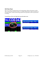
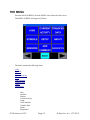
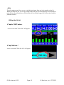
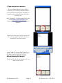
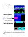
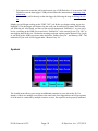
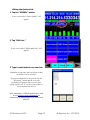
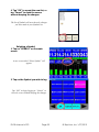
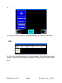
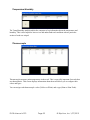
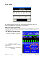
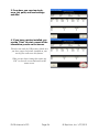
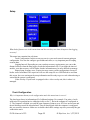
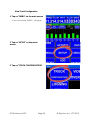
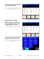
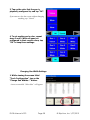
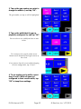
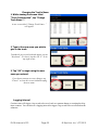
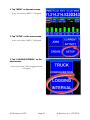
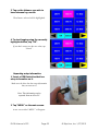
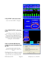
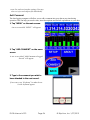
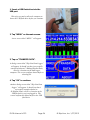
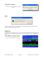
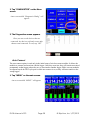
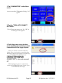
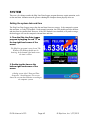
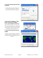
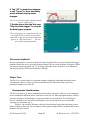
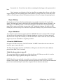
Skip-Line Data Logger
DL-08
DL-08 Manual v0.93
Page 1
© Skip-Line, Inc. 1/27/2010
DL-08 Manual v0.93
Page 2
© Skip-Line, Inc. 1/27/2010
Table of Contents
Definitions...........................................................................................................................................4
The Main Screen..................................................................................................................................5
Changing Items to monitor on the main screen..............................................................................5
Changing an Item's parameters and warning levels........................................................................7
Switching Pages............................................................................................................................12
The Menu...........................................................................................................................................13
Jobs...............................................................................................................................................15
Editing the Job list....................................................................................................................15
Selecting a Job to log...............................................................................................................17
Symbols.........................................................................................................................................19
Editing the Symbols list...........................................................................................................19
Sensors..........................................................................................................................................22
GPS...........................................................................................................................................22
Temperature/Humidity.............................................................................................................23
Thermocouple...........................................................................................................................23
Current Activity............................................................................................................................24
Setup..............................................................................................................................................26
Truck Configuration.................................................................................................................26
Logging Interval.......................................................................................................................31
Importing setup information.....................................................................................................33
Add Comment...............................................................................................................................35
Transfer Data.................................................................................................................................36
About.............................................................................................................................................38
Diagnostics....................................................................................................................................38
Auto Connect............................................................................................................................39
System................................................................................................................................................41
Setting the system date and time...................................................................................................41
On-screen keyboard......................................................................................................................43
Proper Care ..................................................................................................................................43
Environmental Considerations.................................................................................................43
Proper Startup...........................................................................................................................44
Proper Shutdown......................................................................................................................44
Warranty, Warnings, and Disclaimer................................................................................................45
DL-08 Manual v0.93
Page 3
© Skip-Line, Inc. 1/27/2010
DEFINITIONS
Here are definitions of items, terms, or actions that appear in several steps:
–
–
–
–
–
–
–
–
–
–
–
–
–
–
–
CLICK: Tap on the screen with your fingernail or another non-sharp object (such as a
stylus) to cause a click, or press the left-click button.
RIGHT-CLICK: Tap on the right-click button. This will usually bring up a small list
of special options.
ON-SCREEN KEYBOARD: An image of a keyboard that appears on the screen
which you can use to type things in without requiring a physical keyboard attached to
the computer.
BACK: Tap "Back" to return to the previous screen without making changes.
CANCEL: Tap "Cancel" to close the current screen without saving changes.
OK: Tap "OK" to approve any changes you have made on the current screen and return
to the previous screen.
PARAMETERS: Information that defines what's on the screen, how the screen looks,
and how thresholds, or specific levels that help alert you of changes in a particular item,
are displayed.
FONT: The typeface or style of text.
IMPORT: In this manual, IMPORT means to copy setup parameters into the logger
from an external computer via USB flash drive or other peripheral. For example, a
supervisor may have saved a file of parameters such as job list, crew list, and user
interface settings. This file can be imported into the truck's logger computer.
USB FLASH DRIVE: A small device about the size of a thumb that plugs into the
computer. This is the way information information is moved to and from the hard drive.
USB PORT: The connection spot where you can plug a USB flash drive or another
USB peripheral into the system.
IMPROPER SHUTDOWN: Turning the truck's ignition off before following
proper shutdown procedures is considered improper shutdown. This can cause
permanent damage to your data logger. See “Proper Shutdown” for procedures that
must be followed before turning off the truck.
JOB: A data field which designates or describes a name or venue of work. This can
contain a Job number or brief label describing a section of work.
SYMBOL: A data field which contains tags, labels, or references to group or sort
records for a report. Functionally, this is the same as a Job, but Symbols are assignable
independently from jobs. Symbols may be used to group Jobs.
COMMENT: A data field which contains descriptive sentences or reference notes.
Comments may be assigned to individual records for the purpose of associating events
or observations with a particular record.
DL-08 Manual v0.93
Page 4
© Skip-Line, Inc. 1/27/2010
THE MAIN SCREEN
After the logger computer power is applied, the Main Screen screen always appears first. If the
logger has already been on, and any other screen is displayed, you can click the “BACK” button
repeatedly until the main screen appears.
The main screen lets you view several items that can help your performance during striping
operations. There are many available items that you can set depending on your own preferences or
needs. You can configure thresholds on these items so that you will be warned when there are items
on the truck that require your attention, and correct them before they become a problem.
Changing Items to monitor on the main screen
You can change the items that you wish to view on the main screen. Later you can set warnings to
appear on these items when they reach certain levels, such as when you begin to run low on paint
or beads, or if your speed is out of a specified range.
1. Right-click on the item you wish to
change.
DL-08 Manual v0.93
Page 5
© Skip-Line, Inc. 1/27/2010
2. Tap on “Change Item ...”
A screen titled “Change Display Item Selection
Dialog” will appear.
3. Select the item you want to have
displayed on the main screen.
The following options are available. The item being measured is displayed first, followed by the
unit of measurement.
Vehicle Speed - Miles per Hour
Yellow Paint - Gallons per Mile
Yellow Paint - mil thickness
White Paint - Gallons per Mile
White Paint - mil thickness
Black Paint - Gallons per Mile
Black Paint - mil thickness
#1 Beads - Pounds per Gallon
#2 Beads - Pounds per Gallon
Total Beads - Pounds per Gallon
Yellow Paint Tank - Gallons
Yellow Paint Used - Gallons
White Paint Tank - Gallons
White Paint Used - Gallons
Black Paint Tank - Gallons
Black Paint Used - Gallons
#1 Beads Weight - Pounds
#2 Beads Weight - Pounds
Air Temperature - degrees F
DL-08 Manual v0.93
Page 6
© Skip-Line, Inc. 1/27/2010
Road Temperature - degrees F
Average Yellow Paint - Gallons per Mile
Average Yellow Paint - mil thickness
Average White Paint - Gallons per Mile
Average White Paint - mil thickness
Average Black Paint - Gallons per Mile
Average Black Paint - mil thickness
Average #1 Beads - Pounds per Gallon
Average #2 Beads - Pounds per Gallon
Average Total Beads - Pounds per Gallon
The measurements above are also listed in metric units.
4. Tap “OK” to apply the change.
You should now see the new item in place of the
previous item you right-clicked.
Changing an Item's parameters and warning levels
Changing the parameters and warning levels, of a certain item will help you monitor changes in the
system. You can set the level, by either percentage or actual value, when an item changes from
green to its yellow warning color. This helps your crew run more efficiently and reminds the
operator to take action before a problem arises. You can also change labels and font sizes to make
the item more meaningful or clear.
1. Right-click on the item that you
want to change the parameters of.
A pop-up menu will appear. Make sure you
right-click over the item you want to change.
DL-08 Manual v0.93
Page 7
© Skip-Line, Inc. 1/27/2010
2. Tap “Change Parameters ...”
"Change Display Item Parameters Dialog"
will appear.
3. Change the parameters to match
your requirements.
The following parameters are available:
Description: Displays the description of the
item. This item is not changeable.
Label: The text that describes the item.
Example: You right-clicked on an item that
says "SPEED". You may want to change the
label from "SPEED" to "VELOCIDAD" to be
more useful for a Spanish-speaking operator.
NOTE: Be careful! Changing this parameter
does NOT change the value this item
measures. Example: You right-clicked on an
item that says "SPEED". The description says
"Vehicle Speed - Miles per Hour". You change the label to say "WHITE TANK". This label will
NOT show the level of paint in the white paint tank but will still show the truck speed in MPH as
the description says, and will be confusing to the operator. To change the item, see section 1.1
(above) and follow the instructions on "Selecting items to monitor on the main screen".
DL-08 Manual v0.93
Page 8
© Skip-Line, Inc. 1/27/2010
Units: The text that describes the unit of
measurement.
NOTE: Be careful! Changing this parameter
does NOT change the method of measurement.
Example: You right-clicked on an item that
says "SPEED". The description says "Vehicle
Speed - Miles per Hour". You change the label
to say "Kilometers/Hour". This label will NOT show the speed in Kilometers per hour but will still
show the truck speed in MPH as the description says, and will be confusing to the operator. To
change the item, see section 1.1 (above) and follow the instructions on "Selecting items to monitor
on the main screen".
Label Font Size: The size the text in the
label will be displayed.
NOTE: It is possible to change the label to a
larger size than is able to fit inside the item. If
you cannot view all of the text with the text
size you selected, try a smaller label font size.
Value Font Size: The size of the item will
be displayed as a number.
NOTE: It is possible to change the value font
size to a larger size than is able to fit inside
the item. Use a font size large enough to
easily see, but not so large that higher
numbers don't fit.
DL-08 Manual v0.93
Page 9
© Skip-Line, Inc. 1/27/2010
Lower Limit: The lowest allowable value
for the item.
Example: You right-clicked on an item named
"SPEED". The description says "Vehicle
Speed - Miles per Hour". You set the lower
limit to 10. Whenever your speed equals or
falls below 10 miles per hour, this item's
color will become RED to indicate truck
speed is outside of desired range.
Target Value: The value at which the
operation is in peak efficiency.
Upper Limit: The highest allowable value
for the item.
Example: You right-clicked on an item named
"SPEED". The description says "Vehicle
Speed - Miles per Hour". You set the upper
limit to 20. Whenever your speed equals or
rises over 20 miles per hour, this item's color
will be RED to indicate truck speed is outside
desired range.
Yellow Warning Method: Select whether
you want a yellow warning based on a real
value or on a percentage. Changing this value
will allow you to change either the lower and
upper warning levels or the percentage
warning level depending on whether you
select "By Value" or "By Percentage".
DL-08 Manual v0.93
Page 10
© Skip-Line, Inc. 1/27/2010
Lower Warning Level: When "Yellow
Warning Method" is set to "By Value", you
can set the level at which you want the item to
change to the yellow warning color. Example:
You right-clicked on an item named
"SPEED". The description says "Vehicle
Speed - Miles per Hour". You set "Lower
Warning Level" to 10.5. When truck speed
equals or falls below 10.5 miles per hour, this
item's color will become YELLOW to indicate
the truck speed is near the desired limit.
Upper Warning Level: When "Yellow
Warning Method" is set to "By Value", you can
set the level at which you want the item to
change to the yellow warning color. Example:
You right-clicked on an item named "SPEED".
The description says "Vehicle Speed - Miles per
Hour". You set the value to 19.5. When truck
speed equals or rises above 19.5, this item's
color becomes YELLOW to indicate the truck
speed is near the desired limit.
Percentage Warning Level: When
"Yellow Warning Method" is set to "By
Percentage", you can set the percentage at
which you want the item to change to the
yellow warning color. Example: You rightclicked on an item named "SPEED". The
description says "Vehicle Speed - Miles per
Hour". You set the percentage to 10%.
Whenever the truck speed gets within 10% of the range you have set in the "Lower Limit" and
"Upper Limit" boxes, this item's color becomes YELLOW to indicate that truck speed is nearing
the desired limit.
4. When you have set the
parameters as desired, tap “OK”.
If you aren’t sure you want to keep these
changes, or you don't want to change
anything, tap "Cancel".
DL-08 Manual v0.93
Page 11
© Skip-Line, Inc. 1/27/2010
Switching Pages
There are two Pages of information that can be independently configured and quickly switched.
This is useful for trucks with many sensors, or to separate different types of data. For instance, all
of the gun statistics could be on the first Page and all of the temperatures could be reported on the
second Page.
To switch Pages, click on the Skip-Line logo on the main screen.
DL-08 Manual v0.93
Page 12
© Skip-Line, Inc. 1/27/2010
THE MENU
From the MAIN SCREEN, click the MENU icon at the left of the screen.
The MENU SCREEN will appear as follows:
The menu contains the following items:
Jobs
Symbols
Sensors
Current Activity
Setup
Add comment
Transfer Data
About
Diagnostics
Jobs
Symbols
Sensors
Current Activity
Setup
Add Comment
Transfer Data
About
Diagnostics
DL-08 Manual v0.93
Page 13
© Skip-Line, Inc. 1/27/2010
These settings can help your crew log the data correctly and effectively so that the data
logged will be accurate and useful.
DL-08 Manual v0.93
Page 14
© Skip-Line, Inc. 1/27/2010
Jobs
The job settings menu allows you to switch the data logger from one job to another on the fly.
When you finish one job, you can go straight to the next job site without having to first transfer or
print the data. By selecting a new job from the job list, the data logged will be associated with the
job name selected.
Editing the Job list
1. Tap the “JOB” button.
A new screen titled "Select Job" will appear.
2. Tap “Edit List...”
A new screen titled "Edit Job List" will appear.
DL-08 Manual v0.93
Page 15
© Skip-Line, Inc. 1/27/2010
3. Type each job on a new line.
If your computer does not have a built-in
keyboard, press the Keyboard button and an
on-screen keyboard will appear. Remember to
tap Enter after each item so that each item is
on its own line.
Note: Alternately, a USB keyboard can be used
or see Importing setup information for
instructions on importing the job list from an
office PC.
When you are done entering jobs, tap the red
“X” at the top right corner of the on-screen
keyboard to close the keyboard.
4. Tap “OK” to accept the new list, or
tap “Cancel” to close the screen
without keeping the changes.
The list of jobs will show the changes you have
made in your job list.
DL-08 Manual v0.93
Page 16
© Skip-Line, Inc. 1/27/2010
Selecting a Job to log
Use the following steps when you arrive at a new job site.
1. Tap the JOB button.
A new screen titled “Select Job” will appear.
2. Select the job from the list that
matches the job site you are working
at.
If the job site you are working at does not
appear on the list, follow the steps in Editing
the job list for entering additional jobs into the
jobs list.
- The currently selected job will be
highlighted.
3. Tap “OK” to begin logging the job
you just selected.
Example scenario: You have three jobs that you will be working on this week: “HWY 30
E”, “Stafford Ln”, and “Boones Ferry Rd”. There are two methods to enter these job sites into the
jobs list:
DL-08 Manual v0.93
Page 17
© Skip-Line, Inc. 1/27/2010
•
•
Your supervisor creates the job list and exports it to a USB flash drive. You insert the USB
Flash drive into the data logger’s USB port and follow the instructions in Importing setup
information.
You create the job list directly on the data logger by following the steps in Editing the job
list.
Monday you will begin working on the "HWY 30 E" job. Before you begin working, tap on it to
highlight it. The data logger will begin to log the work you do under this job name. Mid-Tuesday
you finish the job. After lunch, you move to the next location named “Stafford Ln”. As you arrive
on site, you bring up the JOBS screen and select “Stafford Ln” as the current job site. Tap “OK” to
start logging data for this site. Wednesday morning you begin working on the Boones Ferry Ln job,
so you bring up the JOBS screen once more and select “Boones Ferry Ln”, and then tap “OK”. The
remainder of your work will be logged under “Boones Ferry Ln”.
Symbols
The Symbol menu allows you to assign an additional parameter to your data on the fly. For
instance, if there are multiple crews that use the same truck, their logged data can be kept separate.
Or if the truck is contracted by multiple counties or cities, the expenses can be properly attributed.
DL-08 Manual v0.93
Page 18
© Skip-Line, Inc. 1/27/2010
Editing the Symbols list
1. Tap the “SYMBOL” button.
A new screen titled “Select Symbol” will
appear.
2. Tap “Edit List...”
A new screen titled “Edit Symbol List” will
appear.
3. Type in each Symbol on a new line.
Remember to tap enter after each item so that
each item is on its own line.
If a physical keyboard is not present, tap the
“Keyboard” button and an on-screen
keyboard will appear. When you are done
typing, tap the red “X” at the corner of the onscreen keyboard to close it.
Note: Alternately, a USB keyboard can be used
or see Importing setup information for
instructions on importing the crew list from an
office PC.
DL-08 Manual v0.93
Page 19
© Skip-Line, Inc. 1/27/2010
4. Tap “OK” to accept the new list, or
tap “Cancel” to close the screen
without keeping the changes.
The list of Symbols will now show the changes
you have made in your Symbols list.
Selecting a Symbol
1. Tap on “SYMBOL” on the main
screen.
A new screen titled “Select Symbol” will
appear.
2. Tap on the Symbol you wish to log.
Tap “OK” to begin logging or “Cancel” to
close the screen without keeping the changes.
DL-08 Manual v0.93
Page 20
© Skip-Line, Inc. 1/27/2010
Sensors
The Sensors screen allows you to view information your logger is receiving from any installed
sensors. Tapping a sensor type will bring up its associated information.
GPS
The GPS module enables the computer to log location information. This can be used after the job is
complete to review exactly where the road was striped and what striping pattern was used on any
given segment of the road. You can know how the road was striped without having to leave the
office.
DL-08 Manual v0.93
Page 21
© Skip-Line, Inc. 1/27/2010
Temperature/Humidity
The Temp/Humidity module enables the computer to log information about the temperature and
humidity. This is also helpful to later review and understand road conditions when a particular
section of road was striped.
Thermocouple
Thermocouples measure paint temperatures in the truck. This is especially important for trucks that
use thermoplastic. This screen displays information about them and allows you to confgure their
colors and types.
You can assign each thermocouple a color (Yellow or White) and a type (Paint or Paint Tank).
DL-08 Manual v0.93
Page 22
© Skip-Line, Inc. 1/27/2010
Current Activity
The Current Activity Report shows the truck’s current settings and statistics at a glance. This
screen is useful to identify any settings that may need to be changed.
Viewing the Current Activity Report
There are no changeable options in the current activity report, but this information is here for you
to view at any time. You should refer to other parts of this document to find instructions about how
to change these settings.
1. Tap “MENU” on the main screen.
A new screen titled “MENU” will appear.
2. Tap “CURRENT ACTIVITY” on the
menu screen.
A new screen titled “Current Activity Report”
will appear.
DL-08 Manual v0.93
Page 23
© Skip-Line, Inc. 1/27/2010
3. From here, you can view truck,
crew, job, paint, and bead settings
and data.
4. If you have a printer installed, you
can tap “Print” to print a report of the
information you see on the screen.
This does not work for USB printers. Make sure
you have a tape-reel printer installed on your
truck if you want to use this feature.
When you are done viewing this report, tap
“OK” to close the screen and return to the
menu screen.
DL-08 Manual v0.93
Page 24
© Skip-Line, Inc. 1/27/2010
Setup
What kind of features are in this menu item and how can they save time & improve data logging
accuracy?
This menu item contains four sub items:
Truck Configuration: In this screen you can view your truck name & current paint gun
configuration. You can also configure gun widths and colors, a very important part of keeping
accurate data.
Logging Interval: Depending on your own data accuracy requirements, you can set the
distance between when the data logger records the information to file. If you make the interval
smaller, your data accuracy will be higher, but the information may be more difficult to manage.
Import Setup: In many cases, a supervisor may want to set the configurations for one of
his/her crews beforehand. The supervisor will save this setup file to a USB flash drive and from
this screen, the crew can import the setup information and be ready to go to work without having to
wait while the system is configured.
Video Overlay: If your truck is equipped with a video overlay unit, this is where it is
managed.
Truck Configuration
Why is it important that my truck configuration under this menu item is correct?
The data logger bases its information off of calibrated settings. For example: You paint a 1-mile
solid stripe on a gun that has its width physically set for 5", but in the computer it's configured at
4". The computer will think you used the same amount of paint to cover 20% less surface area and
the mil thickness would be miscalculated. Thus all data logged while the computer is configured
this way would be incorrect. Make sure to double-check these settings any time you modify the gun
width on the truck.
DL-08 Manual v0.93
Page 25
© Skip-Line, Inc. 1/27/2010
View Truck Configuration
1. Tap on “MENU” on the main screen.
- A new screen titled “MENU” will appear.
2. Tap on “SETUP” on the menu
screen.
3. Tap on “TRUCK CONFIGURATION”.
DL-08 Manual v0.93
Page 26
© Skip-Line, Inc. 1/27/2010
4. Tap “OK” when finished editing the
truck configuration page.
To change gun widths or truck name, refer to
the instructions below.
Changing Gun Color Settings
1. While viewing the screen titled
“Truck Configuration”, tap on the
“Change Gun Colors...” button.
A new screen titled “Select Gun” will appear.
2. Tap on the gun number you wish to
change the color of, and tap “OK”.
A new screen titled “Select Gun Color” will
appear.
DL-08 Manual v0.93
Page 27
© Skip-Line, Inc. 1/27/2010
3. Tap on the color that the gun is
physically configured to, and tap “OK”.
If you want to close the screen without changing
anything, tap “Cancel”.
4. To set another gun's color, repeat
steps 2 and 3. When all guns are
configured to their correct colors, tap
“OK” to keep these settings.
Changing Gun Width Settings
1. While viewing the screen titled
“Truck Configuration”, tap on the
“Change Gun Widths...” button.
A new screen titled “Select Gun” will appear.
DL-08 Manual v0.93
Page 28
© Skip-Line, Inc. 1/27/2010
2. Tap on the gun number you wish to
change the width of, and tap “OK”.
The gun number you tap on will be highlighted.
3. Tap on the width that the gun is
physically configured to, and tap “OK”.
You can select a new width from three to nine
inches.
To view more sizes, tap the yellow arrow
buttons on the bottom left and right corners of
the screen.
If you want to close the screen without keeping
the new configuration, tap “Cancel”.
4. To set another gun's width, repeat
steps 2 and 3. When all guns are
configured to their correct width, tap
“OK” to keep these settings.
DL-08 Manual v0.93
Page 29
© Skip-Line, Inc. 1/27/2010
Changing the Truck's Name
1. While viewing the screen titled
“Truck Configuration”, tap "Change
Truck Name ..."
A new screen titled “Change Truck Name...”
will appear.
2. Type in the new name you wish to
give to the truck.
To make the on-screen keyboard appear, tap on
“Keyboard”. To close it, tap the red “X” on its
top right corner.
3. Tap “OK” to begin using the new
name you entered.
If you do not want to save any changes, tap
“Cancel” to close this screen without keeping
the new name.
Logging Interval
Certain events will trigger a log record to be saved, such as a pattern change or resetting the skiptimer counters. You can also set a logging interval to trigger a log record to be saved based on the
odometer.
DL-08 Manual v0.93
Page 30
© Skip-Line, Inc. 1/27/2010
1. Tap “MENU” on the main screen.
A new screen titled “MENU” will appear.
2. Tap “SETUP” on the menu screen.
A new screen titled “MENU” will appear.
2. Tap “LOGGING INTERVAL” on the
setup screen.
A new screen titled “Select Logging Interval”
will appear.
DL-08 Manual v0.93
Page 31
© Skip-Line, Inc. 1/27/2010
3. Tap on the distance you wish to
have between log records.
The distance selected will be highlighted.
4. To start logging using the currently
highlighted value, tap “OK”.
If you don't want to use the new value, tap
“Cancel”.
Importing setup information
1. Insert a USB flash drive that has
setup information on it.
Make sure the drive has the setup information
that you want on it!
Note: This information can be
exported from an office PC.
2. Tap “MENU” on the main screen.
A new screen titled “MENU” will appear.
DL-08 Manual v0.93
Page 32
© Skip-Line, Inc. 1/27/2010
3. Tap “SETUP” on the menu screen.
A new screen titled “MENU” will appear.
4. Tap “IMPORT SETUP” on the setup
screen.
A new dialog screen titled “Skip Line Data
Logger” will appear. The date and time that the
“import file” on the USB flash drive was
created is shown followed by the date and time
the jobs list on your computer (known as the
“working file”) was last modified.
5. Be sure that the USB flash drive
contains the correct information, then
tap “OK”.
If you do not want to replace the setup
information currently on your computer, tap
“Cancel”.
Depending on how many settings were exported
to the USB flash drive, this dialog may appear
up to three times, once each for the jobs list,
DL-08 Manual v0.93
Page 33
© Skip-Line, Inc. 1/27/2010
crews list, and user interface settings. You may
select or reject each import file individually.
Add Comment
The data logging computer will allow you to add a comment into your data at any time during
operation. This can help you mark events, insert descriptions and include explanations to your data.
1. Tap “MENU” on the main screen.
A new screen titled “MENU” will appear.
2. Tap “ADD COMMENT” on the menu
screen.
A new screen titled “Add Comment to Logged
Record” will appear.
3. Type in the comment you wish to
have attached to the next record.
If necessary, tap “Keyboard” to make the onscreen keyboard appear.
DL-08 Manual v0.93
Page 34
© Skip-Line, Inc. 1/27/2010
When you are done typing, tap the red “X” on
the top right hand side of the on-screen
keyboard to close it.
4. When you are done entering your
data, tap “OK” to save the comment
to the next record.
If you do not want to save the comment you
have written, tap “Cancel” to close the form
without saving the comment to the next record.
Transfer Data
How often should I transfer data?
Transferring data from the truck to the office is necessary in order to have the information available
to create reports. Under normal circumstances, it's a good idea to transfer your data on a regular
schedule, at least once per week but perhaps as often as once per day.
DL-08 Manual v0.93
Page 35
© Skip-Line, Inc. 1/27/2010
1. Insert a USB flash drive into the
USB port.
Wait a few seconds to allow the computer to
detect the USB flash drive before you continue.
2. Tap “MENU” on the main screen.
A new screen titled “MENU” will appear.
3. Tap on “TRANSFER DATA”.
A dialog screen titled “Skip Line Data Logger”
will appear. It should say that it successfully
transferred data to C:\Backup\Skipline\Data,
which is a location on the data logger
computer. This screen confirms data transfer to
a backup file.
4. Tap “OK” to continue.
Another dialog screen titled “Skip Line Data
Logger” will appear. It should say that it
successfully transferred data to
D:\Skipline\Data, which is a location on the
USB flash drive you just plugged in. This
screen confirms the data transfer to the USB
flash drive.
DL-08 Manual v0.93
Page 36
© Skip-Line, Inc. 1/27/2010
5. Tap “OK” to continue.
- The dialog screen will complete its process
and close.
About
The About window displays the version number of the Skip-Line Data Logger software you are
running, as well as the year it was released.
Diagnostics
The Diagnostics screen allows you to view wireless statistics and manage auto-connecting devices.
This is helpful for troubleshooting and setup of wireless sensor modules. To get to the Diagnostics
screen:
1. Tap “MENU” on the main screen.
A new screen titled “MENU” will appear.
DL-08 Manual v0.93
Page 37
© Skip-Line, Inc. 1/27/2010
2. Tap “DIAGNOSTICS” on the Menu
screen.
A new screen titled “Diagnostics Dialog” will
appear.
3. The Diagnostics screen appears.
Here you can see the devices that are
connected. Any devices with only zeroes after
them are not connected. To exit, tap “OK”.
Auto Connect
The auto connect option is used only in the initial setup of wireless sensor modules. It allows the
modules to connect and associate with the logger. Once they associate, they will remain associated
permanently to that logger unless they are re-associated to another logger. Make sure any modules
on adjacent trucks do NOT cycle power while auto connect is on, as they will auto connect to the
wrong logger!
1. Tap “MENU” on the main screen.
A new screen titled “MENU” will appear.
DL-08 Manual v0.93
Page 38
© Skip-Line, Inc. 1/27/2010
2. Tap “DIAGNOSTICS” on the Menu
screen.
A new screen titled “Diagnostics Dialog” will
appear.
3. Tap the “TURN AUTO CONNECT
ON” button.
This will turn auto connect on. Tap “OK” at
the dialog box that appears.
4. Cycle the power on any wireless
sensor modules on the truck you wish
to associate with the logger system.
If they are already associated with your
logger, there is no need to re-associate them.
When they connect, their statisics will show up
on the Diagnostics Dialog screen.
5. When all the modules are
connected, tap “TURN AUTO
CONNECT OFF” to turn auto connect
off.
When the logger's power is cycled, auto
connect will automatically turn off even if you
do not manually turn it off.
DL-08 Manual v0.93
Page 39
© Skip-Line, Inc. 1/27/2010
SYSTEM
There are a few things outside the Skip Line Data Logger program that may require attention, such
as date and time. Attention must be given to shutting the computer down properly after use.
Setting the system date and time
The Skip Line Data Logger can get the date and time from two sources: 1) the computer's system
date and time, or 2) the GPS module. Under normal operation, the GPS module provides the date
and time from its satellite link. However, if the GPS module is not installed, or beyond coverage,
the data logger will use the computer's internal date and time.
1. Close the Skip Line Data Logger
program by tapping the red “X” on
the top right hand corner of the
screen.
The Skip Line program is now closed. The
Windows XP desktop should now be
showing. In the bottom right hand corner,
the time is shown.
2. Double-tap the time on the
bottom right hand corner of the
screen.
A dialog screen titled “Date and Time
Properties” should appear. This screen
shows the current date and time according to
the computer system.
DL-08 Manual v0.93
Page 40
© Skip-Line, Inc. 1/27/2010
3. Correct the shown date and time
as needed.
To change the time, tap on the digits you
wish to change and then tap on the up or
down arrow to raise or lower the value.
4. Tap on the tab that says “Time
Zone” at the top of the dialog
screen (just beneath the blue bar).
The content of the dialog screen will change
to a picture of the world. In the combo box at
the top of the world map, it will say which
time zone you are currently set to.
5. Correct the shown time zone as
needed.
If you live in an area that does not observe
daylight savings time, toggle the check box
just underneath the map so that there is not a
check in it.
DL-08 Manual v0.93
Page 41
© Skip-Line, Inc. 1/27/2010
6. Tap “OK” to keep these changes,
or tap “Cancel” to close the dialog
screen without keeping these
changes.
The screen will close and the desktop should
now be visible again.
7. Double-tap on the icon that says
“Skip-Line Data Logger” to re-open
the data logger program.
This icon appears as a striped road. Due to
the length of this icon title, the end of the
name may or may not be cut off. It may also
appear as “Skip-Line Data L...” You can
now resume normal operation.
On-screen keyboard
In some circumstances you may need the on-screen keyboard when you are not in the Data Logger
program. Should this occur, press the Keyboard button. The on-screen keyboard will appear. When
you are done typing, tap on the red "X" at the top right hand corner of the box. As an alternative,
you may also plug a USB keyboard into the USB port.
Proper Care
The DL-08 is a system based on a personal computer designed to withstand moderately harsh
environments. However, there are some actions that must be followed in order to prevent
permanent damage to your DL-08.
Environmental Considerations
The DL-08 is made to be able to withstand more than most computers. However, most computers
are not installed on industrial trucks. Other devices used in, on, and around paint striping vehicles
can cause damage to the data logger if proper procedures are not followed. The following are
devices commonly in use that can cause damage to your system which is not covered under
warranty. (see disclaimer, pg 3):
Welders: Be certain to disconnect all power from the data logger and skip timing system
before welding on the truck. Do not connect welder ground clamps to frame members that are not
bonded to the truck chassis.
DL-08 Manual v0.93
Page 42
© Skip-Line, Inc. 1/27/2010
Pressurized Air: Do not blow into the box containing the data logger with a pressurized air
hose.
Other important considerations include not installing or running other software on the data
logger computer (such as installing games, other software, viewing DVDs, etc). These may cause
conflicts with the logger software and impair performance. Do not re-image the operating system.
Proper Startup
Pressing the power button after the ignition/main power switch is turned on will start the data
logger. The data logger must be allowed to fully start BEFORE turning the power off again. If the
data logger is accidentally turned on, DO NOT immediately turn the power off. The data logger
must reach its main screen before you may shut it off. Turning the computer off while it is still
booting may cause necessary files to become corrupt and eventually it may cause hard drive failure.
Proper Shutdown
Any computer system must be properly shut down BEFORE the truck is turned off. Even though
you may not see the immediate effects of improper shutdown, over time it will cause necessary
files to become corrupt and eventually it will cause hard drive failure. When this occurs, the data
logger may become unreliable or completely unusable.
1. Press the POWER button.
One press is all that is necessary. DO NOT hold the “POWER” button down for more than one
second or press it more than once.
The Skip-Line program will close and Windows will begin to shut down. The entire shutdown
process takes about 20 to 30 seconds.
2. Wait for the monitor to turn off.
The screen should black out and the power light should turn off. When you see this, it is safe to
turn off the power supply (ignition, main power switch, etc.)
NOTE: Should you not reach this screen after several minutes, press and hold the “POWER”
button for four seconds. The system will be forced to power down. This is NOT the ideal method of
power down and should only be used if the computer will not otherwise shut down.
DL-08 Manual v0.93
Page 43
© Skip-Line, Inc. 1/27/2010
WARRANTY, WARNINGS, AND DISCLAIMER
Skip-Line warrants the Data Logger for repair or replacement of defective materials or
workmanship for one year from original use, FOB our factory in Oregon.
The Skip-Line DL-08 data logger is a useful tool for monitoring and recording pavement-markings
application rates. It is intended to assist the paint machine operator to recognize and compensate for
materials delivery “on-the fly”, and provide temporal and geographic records of areas painted.
Logger and Monitor calibration is determined by operator entry, based on comparison of known
values loaded from material stockpiles.
The PRIMARY source of application rate verification depends on DAILY comparison of
actual inventory quantities loaded and consumed against logger values displayed and
recorded. Do not continue reliance on this logger when significant discrepancies exist
between inventory consumption and logged quantities.
Improper calibration settings cause erroneous results. Calibration problems may stem from operator
error, electrical spikes, hard physical impacts, or component failure. Footage calibration values
may be affected by truck tire diameter, large payload variation, or integrity of motion sensors and
sensor plates.
All electronic equipment is subject to failure.
Some causes: non-compatibility of accessories or user-added software, extreme mechanical
vibration, electrical spikes, exposure to highly inductive (noisy) power sources, temperature
extremes, induced load-dump and welding currents, improper wiring, poor cable routing, insulation
chafing, stressed mounting, over-voltage applied, mechanical impacts.
On equipment with on-board hard drives, improper shutdown procedure can lead to intermittent
failure or loss of data.
Indiscriminate high-pressure washing can cause moisture intrusion and corrosion.
Most sensors, such as motion sensors, weigh scales, flow meters, and pump-stroke switches are
provided by third parties, and their performance is not under the control of Skip-Line, Inc.
Even space mission computer systems can fail. Software bugs can appear.
Skip-Line, Inc. will not be responsible or liable for any loss as a result of the use of this device or
software, including but not limited to: loss of time, money, compensation, opportunity reputation,
nor due to re-work. Verify your inventory use!
Software & Firmware are © 2006-2009.
DL-08 Manual v0.93
Page 44
© Skip-Line, Inc. 1/27/2010