1
COMPIX® Meditherm 520
Thermal Imaging System
with
Threshold Detection
Installation and Operating Instructions
Version 2.1
3/21/2013
Please check http://www.compix.com/TemperatureMonitoringHelp for latest updates.
NOTICE
This manual is intended solely to provide instructions for operation of the Compix Meditherm 520 Temperature Monitoring Station and the
accompanying software. Compix reserves the right to change the information contained in this manual without notice. No warranty, expressed or
implied, is made regarding the accuracy of the information in this manual at any time following its release or for any purpose other than as a guide to
operation of Compix Systems.
Copyright © 2013 by Compix Incorporated, Tualatin, Oregon. All rights reserved.
Compix is a registered trademark of Compix Incorporated. Microsoft, Windows XP, Windows VISTA, Windows 7, and Windows 8 are
trademarks or registered trademarks of Microsoft Corporation. All other brand and product names are trademarks or registered trademarks
of their respective companies.
1
Table of Contents
TABLE OF CONTENTS ........................................................................................................ 2
1. INTRODUCTION .............................................................................................................. 3
Mounting ................................................................................................................................ 4
3. INSTALLATION AND SET UP........................................................................................ 5
SOFTWARE INSTALLATION .......................................................................................................... 5
HARDWARE INSTALLATION......................................................................................................... 6
SETTING UP THE MEDITHERM 520 .............................................................................................. 8
Parameter Setup Screen ......................................................................................................... 9
4. OPERATING THE TEMPERATURE MONITORING STATION ............................ 12
OPERATING THE MEDITHERM 520 FOR THE FIRST TIME ............................................................ 12
Starting out........................................................................................................................... 12
OPERATING PROCEDURES ......................................................................................................... 13
AUTO SAVE AND REVIEW MODE ............................................................................................... 16
5. OPERATING SUGGESTIONS ....................................................................................... 17
FOCUSING ................................................................................................................................. 17
TEMPERATURE MEASUREMENT ................................................................................................ 17
1. MINIMIZE EXTERNAL SOURCES OF INFRARED ENERGY ...................................................... 17
2. SAVING AND EXPORTING IMAGES ...................................................................................... 17
6. MAINTENANCE.............................................................................................................. 18
CALIBRATION ........................................................................................................................... 18
CLEANING................................................................................................................................. 18
STORAGE AND TRANSPORTING .................................................................................................. 18
7. USER SUPPORT .............................................................................................................. 19
8. COMPIX MEDITHERM 520 LIMITED WARRANTY ............................................. 20
LIMITATIONS............................................................................................................................. 20
SHIPPING................................................................................................................................... 20
APPENDIX A......................................................................................................................... 21
ROLL-ABOUT STAND ................................................................................................................. 21
Assembly ............................................................................................................................. 21
Operation ............................................................................................................................. 21
2
1. INTRODUCTION
The Meditherm 520 is a precision temperature measuring system. It is comprised of an IR Camera, Meditherm 520
Threshold Software, and a personal computer. It is intended for operation as an Infrared based temperature threshold
detection/alarm system.
The rest of this manual describes the Compix® Meditherm 520 system and its operation in more detail.
NOTE
Before attempting to operate the system you should read sections:
2. SYSTEM DESCRIPTION AND OPERATING REQUIREMENTS.
3. INSTALLATION AND SET UP.
4. ACQUIRING THERMAL IMAGES.
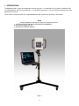
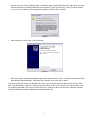
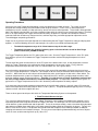
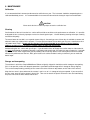
Figure 1
3
2. SYSTEM DESCRIPTION and OPERATING REQUIREMENTS
The Compix® Meditherm 520 includes a 220-series camera (see Figure 1), the Threshold Detection Software and all
necessary power modules and cables. The 220-series camera may be any of the following: Meditherm IRIS 7.5, Compix
Model 222, or Compix Model 222-OEM.
Presently, the Meditherm 520 is designed to work with personal computers (PCs) running Windows XP, Windows VISTA,
Windows 7, or Windows 8 with at least one USB 2 port. The optimal display settings are 800 x 600 pixels with “Preserve
aspect ratio” selected.
Other than the personal computer, no additional accessories or supplies are required. Optional accessories
available include a selection of camera and laptop stands, carrying cases, and alternate lenses.
The Meditherm 520 system has been designed to operate in engineering, factory, office or similar sheltered field
environments.
Mounting
The camera may be mounted on a tripod for stability or convenience. The standard fitting is a ¼”-20 threaded female
connector mounted on the bottom of the camera.
The camera may be located as far as fifteen feet (5 meters) from the Personal computer. A 15-foot USB cable (type A/B
M/M) is provided for connecting the camera to the computer.
NOTE
There are no components inside the camera designed for user service. Opening the camera may void the warranty.
4
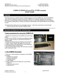
3. INSTALLATION AND SET UP
Unpack the system. Inspect the camera for physical damage. If you find shipping damage, stop, inform the carrier and
call Compix Customer Service. If possible, store the shipping carton and packing materials for future use.
There are two distinct steps in the installation procedure: software installation and hardware installation. You should
perform, in either order, each of these steps before proceeding to the verification phase.
Software Installation
The CD accompanying the system contains the installer for the Temperature Monitoring application software and the
necessary drivers to support the camera. Before proceeding, change the resolution of your monitor to 800x600 pixels.
This will ensure that the picture isn’t distorted when displayed.
Install the Threshold Detection Software
•
•
Double-click “Install_Compix_5221.msi” from the root directory of the installation disk. This installs the
Temperature Monitoring application software
Copy the files “Language.ini” and “Double-click to reset CODE.reg” to the same folder in which you installed the
application software, usually “c:\Program Files\Compix 5221”. Copy “User Guide.pdf” to the My Documents folder.
Copy the Internet shortcut “Help for Temperature Monitoring” to the My Documents folder. Refer to “Install
Notes.txt” for a summary of the installation procedure and for any last-minute revisions.
5
Hardware Installation
Install the hardware and drivers
Connect the USB cable between the computer and the 220 Camera. Connect the power module to a suitable source of
110-250VAC 50-60 Hz power and the low voltage output cable coming from the power module to the DC power jack on the
rear of the camera.
The Installation Backup Disk for the 520 Temperature Monitoring Station contains the necessary USB drivers. Make sure
that CD is in your CD drive before proceeding.
•
•
•
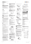
When prompted to “Install New Hardware”, proceed with the default options. This should happen 2 times
depending on the computer’s OS. There will be a series of screens similar to the one shown below.
In the first screen, select “Do not search ...” and click Next.
In the second screen (shown below), if you are installing from a CD and are using Windows XP, select “Install
automatically ... “ and click Next.
Figure 2a
If you are not installing from the software distribution CD, you will need to navigate to the folder in which you have
saved the driver files. On Vista, you will need to navigate to the Drivers folder on the installation CD. In both
cases, select “Install from a list of specific locations (Advanced)” in the window above before clicking Next. In the
navigation window illustrated below, navigate to the Drivers folder of the distribution folder or drive.
Figure 2b
6
•
After you click next in the preceding window, a window will appear dealing with Microsoft “Logo testing” or trusting
the source of the driver software (depending on the operating system you are using). Select “Continue Anyway”
or “Yes, trust this software” or other appropriate response to continue the installation.
Figure 3
•
After installation is finished, press the finish button.
Figure 4
•
When you start the Temperature Monitoring application software for the first time, a second instance of the Found
New Hardware Wizard will begin. Respond to those prompts in the same way as above.
If you are installing the camera on a Windows XP system, you will need to repeat the above process on each USB
port. If you do not do this now, then it may be inconvenient to do so later if the installation CD is not available. If you
are installing on Windows VISTA, then there will merely be a slight pause when you connect to a different USB port
and VISTA will do the hardware installation for that port automatically.
7
Setting up the Meditherm 520
Click on Start. From the Programs menu select 5221 Threshold Alarm or double-click the icon on the
desktop ---->
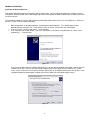
The first time you start the Temperature Monitoring software you will see a message window asking you to enter an
access code.
Figure 5
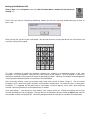
When you click OK, you will see the screen below. You will need to create a security code of from 4 to 16 characters and
enter it by clicking on this keypad.
Figure 6
This code is designed to protect the application software from accidental or unauthorized changes to the setup
parameters, and to limit operators’ ability to access other features of the computer. Once the program is started, this
code will be needed to exit the program or change the operating parameters. Normally, the computer will be configured to
start the program automatically when it is turned on as described below.
After successfully entering a code, the parameter setup screen will be visible as shown in Figure 7. The next several
paragraphs discuss each of the groups of buttons and parameters available here. For a quick first pass at setting these
parameters, it is suggested the threshold value be set between 34 and 35 degrees, and a alarm sound should be
selected. Remaining parameters can be adjusted later as needed.
Click “Save Settings”. If you do not use “Save Settings”, your changes will be lost. Clicking Save Settings will also start
the main operating phase of the software. You may return to the parameter setup by clicking the Menu button from the
main window, and then selecting SETUP. You will be prompted to enter the code you just created as described above.
8
Parameter Setup Screen
Figure 7
Threshold Trigger Group
•
Minimum Selectable Temperature. This is the lowest value to which the "Threshold Temperature" may be
adjusted.
•
Maximum Selectable Temperature. This is the highest value to which the "Threshold Temperature" may be
adjusted.
•
Range of Displayable Temperatures. This sets the fixed distance between the lowest and the highest
temperatures that will be displayed in the colors depicted by the color shown below the "Default Colormap" button.
The actual value of the bottom and top of this range will be controlled by the Threshold setting. The value
currently in use for the Trigger Temperature (or Threshold) is always at the 75% point between the bottom and
top of the range. For example, if the Range of Displayable Temperatures is set at its default value of 10, and the
Trigger Temperature is adjusted by the operator to a value of 32.5, then the bottom of the range will be 25 and the
top will be 35. Another example: for a Range of 20, if the Trigger Temperature is 36, the bottom will be 21 and
the top will be 41. (75% of the Range of 20 is 15, and 15 below 36 is 21.)
•
Default Trigger Temperature. Operators are expected to be trained to adjust the value of the Trigger
Temperature in response to current conditions. This parameter merely sets the value of the Trigger Temperature
when the program first begins. Adjust it using the slider bar, or by editing individual digits of the displayed value.
9
Threshold Autoset Parameters Group
•
Enable Temperature. In Autoset mode, the program attempts to learn from a series of observation based on
subjects passing though the field of view of the camera. The Enable Temperature is the temperature value above
which a subject is detected as having come into view. Once a subject is detected, the maximum temperature
detected in the camera’s view is tracked and the highest value it reaches is used to characterize that subject. As
long as Autoset is active, the Trigger Temperature is adjusted after each subject passes by taking the weighted
average of the current Trigger Temperature and the maximum value recorded for the detected subject PLUS the
value of Threshold Delta. The weighting is 90% of the current value and 10% of the last subject’s value.
•
Reset Temperature. When there is nothing within the field of view of the camera that exceeds the “Reset
Temperature” the program concludes that the subject has passed out of view. There should be at least a small
gap between the Enable Temperature and the Reset Temperature to avoid double counting the same subject.
•
Threshold Delta. This determines how much above the average subject temperature to set the Trigger
Temperature. For example, if Autoset has determined the average subject's peak temperature is 34.7 Deg-C and
if the Threshold Delta is 1.0, then the Trigger Temperature will be 35.7 Deg-C
Colormap
•
Default Colormap (button). The operator may change the colormap by clicking the "Colors" button at any time.
This parameter selects which colormap will be used when the program is first started. Clicking this button will
open a window to navigate to a colormap file. The folder containing a variety of colormaps is "c:\Program
Files\Compix 5221\Colormaps". Open a file from that folder and its colormap will be displayed below this button.
The gradually lightening green scale that switches to red for Over Range (named "Greenscale_RedOR.colormap)
is the one generally found most useful. These colormaps are simple text files and advanced users may edit them
to produce their own custom colormaps.
Threshold Detection Events Group
•
Default Alarm Sound (button). Clicking this button opens a window to navigate to a .wav file to be used for the
Alarm sound. The folder containing a variety of suitable .wav files is "c:\Program Files\Compix 5221\Alarms".
After opening a file from this (or any other location), the Alarm sound may be tested by clicking the "play" button
(triangle symbol) below the Default Alarm Sound button. Adjust the loudness using the computer's volume
control.
•
Save Triggering Images check box. If this box is checked, images that cause alarms will automatically be saved.
Checking this box also enables the following two controls.
Image Save Delay. This value, in seconds, controls the length of time after an image is saved before another
alarm event can cause another image to be saved.
Days in Archive. Saved images older than the specified number of days will be automatically deleted from the
computer’s hard drive. A value of zero is valid and would cause any images from the prior day to be deleted, thus
saving images for only the current day. The maximum is 10 days. If it is necessary to save images longer than
10 days, the system administrator will need to manually move those images to another folder or storage media
from time to time.
•
•
Control Buttons
•
New Code button. Click this button to change your access code.
•
Save Settings button. Be sure to click this button if you have made any changes to any of the parameters
described above. If you do not use the Save Settings button, you will lose the changes after you exit. When the
Save Settings button is used, the current set of parameter will become the initial set of parameters to be used the
next time the Threshold Detection software is launched. Using the Save Settings button automatically resumes
normal operation.
•
Resume button. Clicking this button will resume normal operation without saving any parameter changes.
•
Exit to Desktop button. Clicking this button will terminate the Temperature Monitoring Station software and
enable you to use the general functions of the computer accessible from its desktop. If you wanted to shutdown
10
the computer, you could have used the Off button instead of the setup button when you clicked the Menu button
from normal operation.
After the initial adjustment of parameter, the system is now ready for operation. Be sure to click Save
Settings when you are done. Subsequent launching of the application by clicking the desktop icon shown
below will not bring up the setup screen. To access the setup screen again, start the application, then
Click the Menu button, then click SETUP.
When you are satisfied that the installation of the software is complete and satisfactorily configured, you may want to
setup the computer so that it will start automatically whenever the computer is turned on. To do this, copy the shortcut
icon illustrated above to the folder, "c:\Documents and Settings\All Users\Start Menu\Programs\Startup\" or equivalent
locations in other environments or on other operating systems.
11
4. Operating the Temperature Monitoring Station
Once you have completed the set-up steps of section 3, the system is ready for operation.
Operating the Meditherm 520 for the first time
Start Meditherm 520 software by clicking Start, then Programs, then click on “5221 Threshold Alarm” or double-click its
desktop icon
The threshold display as shown in Figure 8 will be on screen.
The color bar above the image window shows the range of temperatures the camera is displaying. The threshold point is
the point at which an alarm is initiated, and the point where the color bar abruptly changes from green to red.
Figure 8
Starting out
•
•
Point the camera at the scene to be monitored. Rotate the lens to achieve optimum focus.
Set the threshold to the desired alarm temperature, typically 1 or 2 degrees above normal subjects' peak
temperature, or about 35 to 36 Degrees Celsius.
The system is now ready for operation.
Operating Controls and Buttons
•
•
•
•
•
The Threshold Temperature (also referred to as the Trigger Temperature) is set by moving the slider up or
down until the desired alarm point is set.
o Moving the bar up makes the system more sensitive and increases the number of Alarm events by
lowering the value of the Trigger/Threshold temperature.
o Lowering the slider makes the system less sensitive and produces fewer Alarm Events by increasing
the Trigger/Threshold temperature.
The Auto Set button puts the system into Auto Set mode. Using Auto Set is described in further detail below.
The Pause button freezes the display to enable a scene or subject to be examined further. It can also be
used to stop the occurrences of Alarm sounds when the system is not in use.
Clicking the Colors button will toggle through the available colormaps.
The Menu button can be used to end Temperature Monitoring. When the Menu button is clicked, the small
window shown below will pop up giving you the choice to turn off the computer, enter the Setup screen, enter
the review mode to examine recently saved images, or resume normal monitoring operation.
12
Operating Procedures
Successful use of the Temperature Monitoring system may depend on a number of factors. The system has been
designed with enough flexibility to accommodate a wide range of situations. Factors such as room temperature,
atmospheric pressure, humidity, air-flow and near-by sources of heat can affect operation. These factors affect operation
both in the operating environment, and in the environment from which the subjects have recently been located. Therefore,
there is no single setting of the Trigger threshold that will always be optimum. Operators will need to be trained to
understand how the situation may change over time, and from day to day, and make appropriate adjustments to the
Threshold trigger or operating procedures.
Proper use of any of these techniques depends on understanding how the Trigger Temperature setting and display work
together. In all of the following discussion and examples, the system is presumed to be operating with
•
The default temperature range of 10°C from bottom to top of the color range.
•
The default colormap, the gradually lightening green scale that switches to red for Over Range
(named "Greenscale_RedOR.colormap)
The Trigger Temperature defines the 75% point of the color scale. Since the Trigger Temperature is at the 75% point,
there will be a span of 2.5°C between the Trigger Temperature and the maximum displayed temperature in these
examples.
The transition from green to red also occurs at the 75% point in the default color scale. As the temperature increases
above the Trigger Temperature, the red becomes lighter throughout the “over range” region. Finally, when the
temperature exceeds the top of the color scale, it is colored a dark red. See Figure 8 above.
Any surface whose temperature exceeds the maximum of the range will be regarded as being equal to the maximum.
Thus, if the Trigger temperature is set too low -- for example set to 30°C then the maximum of the temperature scale will
be 32.5°C. Most of the face of most subjects will be above that value, and will appear in dark red as shown below. The
maximum temperature the system can report for any subject will be 32.5°C which is not high enough to make a useful
distinction between normal and fevered subjects. Therefore, it is critical to use a Trigger Temperature no lower than
the value, usually between 34.5 and 35°C, of normal healthy subjects. To improve the selectivity of the system, it is
typical to use a Trigger Temperature of at least 1.0°C above the peak temperature of healthy subjects.
It has been found that the peak temperature observed on the face of healthy subjects is typically 2.0 to 2.5°C below the
normal core temperature for healthy subjects which is 37.0°C (98.6°F). That peak temperature typically occurs in the eye
sockets on either side of the bridge of the nose.
There are three general techniques with which the Temperature Monitoring System can be operated.
1. Fixed Threshold Alarm technique.
This is the most typical technique, in which the Trigger Threshold is set to produce the audible alarm and draw a circle
around the portion of the image that exceeds the Trigger Threshold. This technique uses the least amount of technical
skill on both the system administrator and the operator. To use this technique reliably, select a threshold setting that does
not produce an audible alarm and graphic circle drawn around the hottest point for the majority of subjects. Typically, this
will be a value of 35.5 to 36.5°C.The operator will need to know how to adjust the threshold up and down to adapt to
changing environmental and situational changes. This may necessitate adjusting it downward briefly until most subjects
cause an alarm, and then moving it back up by 1.0 to 1.5°C.
13
2. Relative Area of above normal temperature technique.
This technique may be useful when environmental or situational circumstances are erratic. In this technique, the operator
is called upon to exercise a greater degree of skill and judgment. The Trigger temperature is adjusted to a lower value
than in technique 1, such than average (or even the majority of) subjects produce alarms. The alarm is not actually relied
upon in this technique, and the administrator having access to the setup panel may choose to turn off the alarm, or adjust
the system speaker volume to zero.
Normal healthy subjects will produce an alarm marked by the graphic circle in just a few small areas, typically the eye
sockets. Slightly warmer subjects will have larger blotches of red and pink displayed, with the graphic circle marking the
warmest area, and the value of that peak temperature will be displayed in the upper right corner.
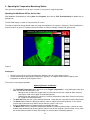
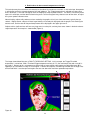
Subjects with a significant fever will have very large areas in red or pink, and may have areas shown in the dark red overrange temperature. An example is shown below (Figure 9).
Figure 9
The image shown below illustrates a FAULTY THRESHOLD SETTING. In this example, the Trigger/Threshold
temperature is set too low. With a Threshold/Trigger temperature of only 31.5°C, the maximum of the color scale “A” is
only 34.0°C. Because of this, no temperatures above 34.0 are represented, and therefore the Object Maximum “B” is
reported as just 34.0 when in reality it is much higher. A further consequence, and warning indication are the large areas
of Dark Red which is used to represent regions that are at or above the maximum reportable temperature.
Figure 10
14
3. Automatic Threshold Adjustment Technique
This technique requires the most skill and care in order to use it properly. However, when used properly it may require the
least amount of ongoing adjustment.
To put the system in Automatic mode, click the "Auto Set" button. The Auto Set button will flash slowly as long as it is
operating in Automatic mode. To use the Automatic mode wisely, it is helpful to understand how it works.
The system attempts to detect the passage of each individual subject. In order to do this, there must be enough space
between subjects passing through the view of the camera to allow the detection process to function. Two of the
"Threshold Autoset parameter" control the subject detection process: When any point in the camera's view exceeds the
Enable Temperature parameter (default value of 30°C), the system assumes a new subject has come into the camera's
view. As long as the subject is in view of the camera, the peak temperature of the subject is tracked. The maximum value
of that subject is noted and used in the Threshold adjustment calculation. When no portion of the image exceeds the
Reset Temperature parameter (default value of 29°C) that subject is assumed to have passed out of view.
The new value of the Trigger/Threshold temperature is calculated by taking the weighted average of the current
Trigger/Threshold temperature and the noted peak temperature of the subject that passed. The weighting is to take 90%
of the current value of the Trigger/Threshold temperature and 10% of the quantity formed by adding the Threshold Delta
parameter (default value of 1.0°C) to the noted peak temperature of the subject that just passed.
The intent of this algorithm is to maintain a Trigger/Threshold temperature that is Threshold Delta above the average peak
temperature of subjects passing through the camera's view. This algorithm will also automatically adjust for environmental
changes affecting the perception of subject's temperature.
To further explain this process, consider the following example: The Trigger/Threshold temperature is currently 35.0°C,
and a subject with a peak temperature of 36.0 passes by. Adding the Threshold Delta of 1.0 produces a value of 37.0.
Then, 90% of 35 is added to 10% of 37 to produce a new Trigger/Threshold temperature of 35.2 . If the majority of
subsequent subjects have peak temperatures of 36.0, the Trigger/Threshold temperature would gradually be adjusted
upward toward 37.0°C
If subjects do not pass through one at a time, the system will not be able to distinguish one subject from the next, and
whenever a gap does occur, it will use the maximum of all the subjects that passed since the last gap. If subjects are
clustered in groups of no more than three or four, this will probably not have too much affect on the validity of the
algorithm, but it will tend to produce a slightly higher than optimum value for the Trigger/Threshold temperature. The
operator must periodically check the current value being used for the Trigger/Threshold temperature to make
sure it is within a reasonable range.
The third technique can be used in combination with the first technique by operating the camera for a short period of time
in the Automatic mode. After at least ten subjects have passed, click the Auto Set button again to turn off the Automatic
mode, leaving the Trigger/Threshold temperature at the value determined while in Automatic mode.
15
Auto Save and Review mode
To adjust the parameters controlling Auto Save, refer to the description of the Parameter Setup Screen.
When AUTOSAVE is active, images are saved in a sub folder of the current user’s “My Documents” folder named
“520_Saves”. Each saved image will occupy approximately 1.5Mbytes of disk storage space. They are saved as .bmp
files named with date and time of day using the ISO8601 standard. The ISO8601 pattern is YYYY-MM-DD hh.mm.ss.ff
where YYYY is the year, MM is the month, DD is the day, hh is the hour, mm is the minutes, ss is the seconds, and ff is the
decimal fraction of the second.
To review saved images, click the Menu button in the main operating window. In the resulting sub-menu, click the Review
button. The screen illustrated below will replace the main operating window.
Figure 11.
The first image shown upon entering the review mode will be the most recent image saved. This window differs from the
main operating window in that the file name depicting the date and time is displayed at the bottom, and the buttons have
different functions. Repeated use of the Previous button will sequence backward through time, showing previous autosaved images. The Next button will move forward through time. Clicking the Resume button will resume normal scanning
in the main operating window. The Menu button has its usual meaning as in the main operating window.
16
5. OPERATING SUGGESTIONS
Focusing
The Meditherm 520 camera utilizes a manual focusing mechanism. The camera can be focused at distances as close as
1 meter and out to 15 meters (effectively infinity). In most situations, adjusting for best focus on subjects at 2 to 3 meters
will provide satisfactory focus over the useful range of from 1 to 15 meters.
Temperature Measurement
The Compix® Meditherm 520 is a sensitive instrument that has the capability to detect small temperature differences.
However, non-contact temperature measurements are affected by a number of variables that can change the accuracy of
temperature measurements. The following techniques will help improve the accuracy of measurements made with the
Meditherm 520 system.
1. Minimize external sources of infrared energy
•
The Compix® Meditherm 520 measures temperature by detecting emitted infrared energy, i.e. the infrared
energy generated by the target. Objects also reflect infrared energy from their surroundings.
•
The Meditherm 520 system (or any other infrared system) cannot tell the difference between reflected and
emitted energy. Therefore, reflected energy is a potential source of error. Some reflected infrared (IR) energy
is unavoidable and the Meditherm 520 will automatically compensate for typical levels of external IR energy,
which are uniformly distributed over the target. Nevertheless, it will be helpful to minimize significant sources
of external IR, particularly those that may not be uniformly distributed.
•
Other sources to avoid are direct sunlight coming through a window and shining on the target, or heat from
nearby electronic devices. A general rule of thumb is that if you can feel heat from a source near the target,
then it will affect the accuracy of the image.
2. Saving and exporting images
•
To save a copy of the screen, use the key combination SHIFT – “Print Screen.” Then, exit the Temperature
Monitoring application. Open a graphics program such as Paint (which can be found in Programs Accessories program group). Use Edit - Paste to copy the captured screen image, and then use the File –
“Save As” to make a file copy of the image.
•
You may be able to use Paint to directly print the image, or “Insert” the image as a picture in a word
processing application such as Microsoft WORD, or Open Office WRITE.
17
6. MAINTENANCE
Calibration
It is recommended that instrument performance be verified once a year. The instrument should be compared against a
calibrated blackbody source. It is recommended the instrument be returned to the factory for repair and recalibration.
CAUTION
Never touch the lens or allow any object to touch or strike the lens.
Cleaning
Small amounts of dust or lint on the lens surface will have little or no effect on the performance or calibration. It is possible
to degrade the lens surface by improper or excessive cleaning techniques. Use the following cleaning techniques carefully
and not too frequently.
To remove loose dust or debris, use a gentle stream of dry air. Aerosol-type cans of clean dry air available at camera and
electronic stores are suitable for this purpose. For more persistent loose dust or debris you may use a camelhair brush or
soft cotton swab ("Q-tip"). Do not use lens tissues: Lens tissues intended for eye glasses contain chemical
additives and lens tissues available in camera stores are often not soft enough.
Avoid touching the lens surface with your fingers. If you do need to clean off fingerprints or other more resistant material,
use clean distilled water or acetone to dampen a soft cotton swab, gently dab, and swipe the spot or fingerprint. If you look
at the lens surface under magnification you will probably notice a few tiny defects in the coating that have no measurable
effect on the performance of the lens; But if you mistake such a defect for debris and try to remove it you can make the
defect larger.
Storage and transporting
The container in which the Compix® Meditherm 520 was originally shipped in should be used for storage or transporting.
If this is not possible, make sure adequate protection is provided to avoid damage while in storage or during shipping.
This can be accomplished by providing at least a two inch barrier of foam on top, bottom, and all sides of the camera.
Keep the lens cover in place whenever the camera is not in use, or is in storage or being transported. If you cannot find
the lens cover, wrap the entire camera in plastic film. Take care to stretch the plastic film over the lens and avoid letting
the plastic film come in direct contact with the lens.
18
7. USER SUPPORT
User support is available by phone, mail, e-mail or in person at Compix' offices in Lake Oswego, Oregon. Support will
normally be available from 8:00 A.M. to 5:30 P.M. Pacific Coast Time, Monday through Friday, excluding national holidays.
User support is generally free of charge on issues relating to interpretation of this manual, the proper operation of the
system, routine maintenance and warranty service.
Compix reserves the right to determine, at its sole discretion, the extent of user support made available to any user. A
user may be asked to furnish proof of ownership of a Compix® Meditherm 520 system before receiving support.
For support, contact Compix by e-mail at http://www.compix.com/contak.htm, by phone at (503) 639-8496, by FAX at (503)
639-1934, or by mail at:
Compix Incorporated
Attn.: User Support/PC2000
P.O. Box 885
Tualatin, OR 97062-0885
When contacting Compix, identify yourself as a user of the Compix® Meditherm 520 system and ask for User Support.
It may be helpful for you to have the serial number of your Meditherm 520 system.
Visit http://www.compix.com/ for technical articles, price lists, product photos, and other information on current products.
If you want to visit us in person, please call us at the number above for directions and to make sure the person best
equipped to help you will be available when you arrive.
Our office location/ shipping address is:
Compix Incorporated
15824 SW Upper Boones Ferry Rd
Lake Oswego, OR 97035-4066
19
8. Compix Meditherm 520 LIMITED WARRANTY
Compix warrants to the original buyer that this product shall be free of defects in materials and workmanship and will meet
its published specifications for a period of one year following the date of shipment (the Warranty Period). Warranty service
will be provided for this product if it is returned to Compix Incorporated, shipment prepaid, during the warranty period.
Compix will, at its option, either repair or replace the product at no cost to the buyer, or refund the original purchase price
of the product.
Limitations
This warranty shall not apply to defects resulting from accident, misuse, improper maintenance or unauthorized
modifications.
The remedies described above -- repair, replacement or refund -- are the buyer's sole and exclusive remedies.
Modifications or extensions of this warranty shall be effective only when made in writing, signed by an officer of Compix
Incorporated.
THIS WARRANTY IS EXPRESSLY IN LIEU OF ALL OTHER WARRANTIES, EXPRESS OR IMPLIED, INCLUDING
IMPLIED WARRANTIES OF MERCHANTABILITY AND FITNESS FOR A PARTICULAR PURPOSE. COMPIX SHALL
NOT BE LIABLE FOR ANY DIRECT, INDIRECT, SPECIAL, INCIDENTAL OR CONSEQUENTIAL DAMAGES.
This warranty gives the buyer specific legal rights. The buyer may also have other rights which vary from state to state.
Shipping
During the Warranty Period, Compix will reimburse the buyer for the buyer's reasonable shipping costs for products
returned to Compix from locations in the United States and Canada. Compix will also pay the shipping charges to return
the product to the buyer.
Before returning a product for service, contact Compix Customer Service for return authorization.
Compix Incorporated
15824 SW Upper Boones Ferry
Lake Oswego, Oregon 97035-4066
Voice (503) 639-8496
FAX: (503) 639-1934
E-mail: http://www.compix.com/contak.htm
20
APPENDIX A.
Roll-about stand
Assembly
There is a slide show named “Stand step-by-step.pdf” in the “Meditherm 520 Documents” folder of the software distribution
disk which illustrates in detail the various assembly steps associated with the roll-about stand.
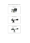
If the stand is not already assembled, attach arm assembly(s) to camera pole. Refer to illustration Figure 1 at the
beginning of this manual. Hand-grip is down with mounting plate facing up for use with the computer support tray. Handgrip is up for use with the camera.
Camera attachment
Attach the camera via the ¼ - 20 nut to the ¼ - 20 thumbscrew of the table top stand.
Computer tray attachment
Insert the mounting stud in the hole of the adjustable arm and securely tighten the wing nut. Adjust height to suit the
intended operation.
Operation
Thumbscrews at pivot points can be loosened, then tightened, to position the camera head as needed.
There are locking brakes on the wheels that may be engaged or disengaged with your foot.
21