1
XDS-100
Installation manual
R9898490
R59770507/03
20/10/2010
Barco nv Simulation Division
Noordlaan 5, B-8520 Kuurne
Phone: +32 56.36.82.11
Fax: +32 56.36.84.86
E-mail: [email protected]
Visit us at the web: www.barco.com
Printed in Belgium
Changes
Barco provides this manual ’as is’ without warranty of any kind, either expressed or implied, including but not limited to the implied warranties or merchantability and fitness for a particular purpose. Barco may make improvements and/or changes to the product(s) and/or the
program(s) described in this publication at any time without notice.
This publication could contain technical inaccuracies or typographical errors. Changes are periodically made to the information in this
publication; these changes are incorporated in new editions of this publication.
Copyright ©
All rights reserved. No part of this document may be copied, reproduced or translated. It shall not otherwise be recorded, transmitted or
stored in a retrieval system without the prior written consent of Barco.
Disposal Information
This equipment has required the extraction and use of natural resources for its production. It may contain hazardous substances for health
and environment. In order to avoid the dissemination of those substances in the environment and to diminish the pressure on natural
resources, we encourage you to use the appropriate take-back systems. Those systems will reuse or recycle most of the materials of your
end of life equipment in a sound way.
The crossed-out wheeled bin symbol invites you to use those systems. If you need more information on the collection, reuse and recycling
systems, please contact your local or regional waste administrator. You can also contact us for more information on the environmental
performances of our products.
Barco XDS Software End-User License Agreement (EULA)
PLEASE READ THIS DOCUMENT CAREFULLY BEFORE OPENING OR DOWNLOADING AND USING SOFTWARE OR HARDWARE
PROVIDED TO YOU BY BARCO AS IT CONTAINS THE TERMS AND CONDITIONS BY WHICH BARCO OFFERS TO LICENSE THE
SOFTWARE. BY OPENING THE SOFTWARE PACKAGE, OR USING THE HARDWARE IN WHICH THE SOFTWARE IS EMBEDDED,
YOU AGREE TO BECOME BOUND BY THE TERMS OF THIS AGREEMENT. The Software as supplied by BARCO is licensed, not sold
to you, on a non-exclusive basis for use only under the terms of this license, and BARCO reserve all rights not expressly granted to you.
You own the disk(s) on which the Software is provided, but the Software is owned and copyrighted by BARCO or by third party suppliers.
Your license confers no title or ownership and is not a sale of any rights in the Software or its documentation.
By installing the Software, either as initial version or as an upgrade, update, patch or enhancement of a prior release, this Software License
shall supersede any terms and conditions previously agreed upon (whether or not in writing) between Barco and you with respect to the
subject matter of this Software License and such previous terms shall from the date hereof cease to have any force or effect; provided,
however that this Software License shall not be construed as a renunciation, discharge or waiver of any right or remedy provided in any
terms and conditions previously agreed upon with respect to a failure of either party to perform any of its obligations under any terms and
conditions previously agreed upon.
Software Specifications
The Software contains 2 main products:
•
- XDS RACU (with Auto Alignment);
•
- XDS Display Wall Software.
Software License Terms
1.
This Software License is between you and BARCO NV, a corporation organized and existing under the laws of Belgium registered
under number BE 0473.191.041, Commercial Companies’ Register of Kortrijk, having its registered office President Kennedypark, 35
at B-8500 Kortrijk, Belgium ("Barco") for the use of the Software.
You hereby undertake to inform all Authorized Users of the terms of this Software License and to bind all Authorized Users to accept all
such terms of this Software License as applies to them. Barco grants you a limited, non-exclusive, non-assignable, non-transferable
license (without the right to grant sublicenses) and right to install the Software on your network for use by you and/or any Authorized
User(s). You agree to notify Barco prior to moving the Software to any network other than the originally installed network.
2.
The Software is licensed to you as a network-enabled product. The Software component parts must not be separated or replicated
in any manner. You and Authorized Users are entitled to use the Software for the purposes and in the manner set out in this EULA
(and documentation), but neither you nor any Authorized User are entitled to: (i) sell or grant a security interest in the Software to
other parties in any way, or to rent, lease or sub-license the Software to others without the express prior written consent of Barco; or
(ii) exploit the Software or any of its component parts for any commercial purpose, other than use by you and/or Authorized Users of
the Software.
3.
Barco shall hold you harmless and indemnify you from and against direct damages, losses and expenses arising from infringement
or alleged infringement of any patent, trademark or copyright of such third party by the license and the right to install the Software as
permitted by this Software License and defend and settle at its sole expense any claim, action, suit or proceeding brought against you,
provided that (i) you promptly notify Barco in writing after a claim has been asserted against you or the commencement of any claim,
action, suit or proceeding, and (ii) Barco shall assume sole control of the defense and any settlement negotiations related to any claim,
action, suit or proceeding, and (iii) you shall not negotiate, settle or compromise any claim, action, suit or proceeding without the prior
written consent of Barco and (iv) you, at your cost, shall cooperate with Barco and provide assistance and support, as may reasonably
required by Barco, in connection with the defense and any settlement negotiations related to any claim, action, suit or proceeding.
Barco shall have no indemnity obligation for any Software, or any portion thereof, (i) that is based on specifications, drawings, models
or other data furnished by you or, (ii) that is not provided by Barco or, (iii) that is modified, in spite of the prohibition for you to modify
the software or, (iv) to the extent that you continue allegedly infringing activity after having been provided modifications that avoid the
alleged infringement, or (v) where the use of the Software, or the combination or thereof with other Software, processes or materials or
the distribution thereof rather than the Software itself is the primary cause of an alleged infringement. In case it has been determined
by a finally awarded judgment that Barco infringed or misappropriated such third party rights or earlier, at Barco’s discretion, it may, at
its option and cost, (i) modify the Software in such a way that it shall not infringe upon or misappropriate the rights of the third party or
(ii) obtain for you a license or other right to use the rights allegedly infringed or (iii) replace the Software in question with non-infringing
Software. The remedies set forth in this paragraph shall constitute your sole and exclusive remedy and Barco’s sole and exclusive
liability for a third party claim that the Product infringes or misappropriates any intellectual property right of a third party.
4.
Barco (and Barco’s licensors, as appropriate) retain ownership of all intellectual property rights in the Software and any copies you or
any Authorized User may make of such Software. The Software is protected by national copyright laws, international copyright treaties
and conventions, and other applicable laws. All rights not expressly licensed to you in this Software License are reserved to Barco
and Barco’s licensors, as appropriate. The Software contains certain other licensed materials and Barco’s licensors may protect their
rights in the event of any violation of this Software License. Neither you nor any Authorized User may, whether in whole or in part,
copy, translate, reverse engineer, derive source code from, modify, disassemble, decompile, create derivative works based on the
Software, or remove any proprietary notices or labels on the Software, save as may be permitted by law or this Software License,
without the prior consent, in writing, of Barco.
This software uses:
-
the OpenSSL library, (c) 1998-2008 The OpenSSL Project. The full license can be found in OpenSSLWin32License.txt;
-
the Crypto++ library, (c) 1995-2009 by Wei Dai. The full license can be found in cryptopplicense.txt
-
the Ogg Vorbis libraries, (c) 2002-2008 the Xiph.org Foundation. The full license can be found in oggvorbislicense.txt;
-
the OpenCV library, (C) 2000-2006, Intel Corporation. The full license can be found in OpenCVLicense.txt
This software is based in part on the work of the Qwt project (http://qwt.sf.net).
5.
The duration of this Software License will be from the date of your acceptance (as set forth above) of the Software, with no termination
date, unless otherwise specified. You may terminate this Software License at any time by destroying all copies of the Software then
in your possession and returning all associated materials and documentation, to Barco or the appointed Barco reseller that sold or
provided these to you. Barco may terminate this Software License forthwith by informing you at any time if you and/or any Authorized
User are in breach of any of the Software License’s terms.
6.
YOU UNDERSTAND THAT THE SOFTWARE IS BEING PROVIDED TO YOU "AS IS". BARCO DOES NOT MAKE NOR INTENDS
TO MAKE ANY WARRANTIES OR REPRESENTATIONS, EXPRESS OR IMPLIED AND SPECIFICALLY DISCLAIMS ALL IMPLIED
WARRANTIES OF MERCHANTABILITY FITNESS, FOR A PARTICULAR PURPOSE AND NON-INFRINGEMENT OF INTELLECTUAL PROPERTY AND DOES NOT WARRANT THAT THE SOFTWARE WILL BE FREE FROM ERRORS OR THAT SUCH ERRORS
WILL BE CORRECTED BY BARCO AND YOU ARE SOLELY RESPONSIBLE FOR ALL COSTS AND EXPENSES ASSOCIATED
WITH RECTIFICATION, REPAIR OR DAMAGE CAUSED BY SUCH ERRORS.
YOU ALSO ACKNOWLEDGE AND AGREE THAT:
BARCO ACCEPTS NO LIABILITY FOR ANY DAMAGES, LOSSES OR CLAIMS YOU OR ANY THIRD PARTY MAY SUFFER AS A
RESULT OF YOUR USE OF THE SOFTWARE, AND YOU HEREBY AGREE TO INDEMNIFY, KEEP INDEMNIFIED, DEFEND AND
HOLD HARMLESS BARCO AND BARCO’S AFFILIATES AND SUBSIDIARIES FROM AND AGAINST ANY AND ALL ACTIONS,
PROCEEDINGS, LIABILITY, LOSS, DAMAGES, FEES AND COSTS (INCLUDING ATTORNEYS’ FEES), AND OTHER EXPENSES
INCURRED OR SUFFERED BY BARCO ARISING OUT OF OR IN CONNECTION WITH ANY BREACH BY YOU OF THE TERMS OF
THIS SOFTWARE LICENSE. TO THE MAXIMUM EXTENT PERMITTED BY LAW, IN NO EVENT WILL BARCO BE LIABLE FOR ANY
INDIRECT, SPECIAL, PUNITIVE, INCIDENTAL OR CONSEQUENTIAL LOSS OR DAMAGES OF ANY KIND WHICH MAY ARISE
OUT OF OR IN CONNECTION WITH THE SOFTWARE, THIS SOFTWARE LICENSE OR THE PERFORMANCE OR PURPORTED
PERFORMANCE OF OR FAILURE IN THE PERFORMANCE OF BARCO’S OBLIGATIONS UNDER THIS SOFTWARE LICENSE
OR FOR ANY ECONOMIC LOSS, LOSS OF BUSINESS, CONTRACTS, DATA, GOODWILL, PROFITS, TURNOVER, REVENUE,
REPUTATION OR ANY LOSS ARISING FROM WORK STOPPAGE, COMPUTER FAILURE OR MALFUNCTION OF THE SOFTWARE AND ANY AND ALL OTHER COMMERCIAL DAMAGES OR LOSSES WHICH MAY ARISE IN RESPECT OF USE OF THE
SOFTWARE, EVEN IF BARCO HAS BEEN ADVISED OF THE POSSIBILITY OF THEIR OCCURRENCE; AND
7.
You shall treat as confidential all information obtained from the other pursuant to this Software License which is marked ’confidential’
or the equivalent or has the necessary quality of confidence about it and shall not divulge such information to any persons without
Barco’s prior written consent provided that this Paragraph 7 shall not extend to information which was rightfully in the possession of
you prior to the commencement of the negotiations leading to this Software License, which is already public knowledge or becomes
so at a future date (otherwise than as a result of a breach of this paragraph 7), is required to be disclosed by law or which is trivial or
obvious. You are aware of and ensure to comply with the provisions of this paragraph 7. The foregoing obligations as to confidentiality
shall survive any termination of this Software License.
8.
You agree with and fully accept the following limited service and support statements.
Barco may limit or terminate any Support Services being provided if you use any Support Services in an abusive or fraudulent manner,
as determined by Barco in its reasonable discretion. Resale, assignment and transfer of ownership are strictly prohibited and will be
grounds for termination of the License Agreement, unless otherwise agreed in writing. A single support incident will be restricted
to support on an issue that focuses on one aspect of the product – e.g. use of a specific documented feature of the product or
assistance with a specific problem or error message. While this issue may involve other aspects of the product, addressing other
aspects constitutes a separate issue and requires an additional support incident. A single support incident may involve multiple phone
calls, emails and off-line research. Barco will determine what characterizes a single support incident and communicating this to you.
Unless a contractual agreement states differently, Barco will make reasonable efforts to resolve the issue but Barco cannot guarantee
that every issue will be resolved.
Barco shall not be obliged to provide any Support Services relating to problems or issues arising out of or from (i) the use of the
Software in a manner for which they were not designed; (ii) damage to the media on which the Software are provided or to the
computer on which the Software are installed; (iii) negligence, misuse, or modification of the Software; (iv) versions of Software other
than the most recent version (e.g., 5.x) and one version back (e.g., 4.x), provided that Barco shall also not be required to provide
any Support Services for Software that are no longer listed on the Barco Site as supported Software; (v) third-party Software and
technologies not associated with network installation assistance or (vii) conflicts related to replacing or installing hardware, drivers,
and software.
You will remain responsible for the maintenance of your hardware, operating system, the functioning of your network and in keeping
your systems virus-free. You acknowledge that the Software is a complex computer software application, and that the performance
thereof may vary depending hardware platform, software interactions and configuration. You acknowledge that the Software is not
designed and produced specifically to meet your specific requirements and expectations and the selection of the Software by you is
entirely your own choice and decision.
The Software has to be installed on a computer delivered by Barco or by yourself. The XDS Racu software is only compatible with
Microsoft Windows XP and Microsoft Windows XP Embedded. The XDS Display Wall Software is only compatible with Microsoft
Windows XP, Vista or Windows 7.
For the avoidance of doubt, nothing in this clause shall impose any obligation on Barco to provide Services not covered by the License
Agreement.
9.
This Software License is the only understanding and agreement between you and Barco for use of the Software by you and/or Authorized Users. The Software License supersedes all other communications, understandings or agreements we had prior to this Software
License (with the exception of any continuing confidentiality agreement) although nothing in this Software License purports to exclude
liability for fraudulent misrepresentation. You may not export or re-export the Software or any copy or adaptation in violation of any
applicable laws or regulations. This Software License shall not be altered, amended or varied. If any provision of this Software License is determined to be illegal, void or unenforceable, or if any court of competent jurisdiction in any final decision so determines,
this Software License shall continue in full force save that such provision shall be deemed to be deleted with effect from the date of
such decision, or such earlier date.
10. You acknowledge that this Software may be subject to U.S. or other governments Export Jurisdiction. You agree to comply with all
applicable international and national laws that apply to the Software, including the U.S. Export Administration Regulations, as well as
end-user, end-use, and destination restrictions issued by the U.S. or other governments.
11. Barco shall be entitled to sub-contract all or any of Barco’s obligations hereunder to a third party and/or any of Barco’s affiliated
companies.
12. The construction, validity and performance of this Software License shall be governed in all respects by the laws of Belgium without
recourse to its conflict of law principles. All disputes arising in any way out of or affecting this Software License shall be subject
to the exclusive jurisdiction of the courts of Kortrijk, without prejudice to enforcement of any judgment or order thereof in any other
jurisdiction.
13. The United Nations Convention on Contracts for the International Sale of Goods (the "Convention") shall not apply to this Software
License, however, if the Convention is deemed by a court of competent jurisdiction to apply to this Software License, Barco shall not
be liable for any claimed non-conformance of the Software under Article 35(2) of the Convention.
eCos
The software in this product uses eCos, the Embedded Configurable Operating System.
This is the license for eCos:
Copyright (C) 1998, 1999, 2000, 2001, 2002, 2003 Red Hat, Inc.
Copyright (C) 2002, 2003 John Dallaway
Copyright (C) 2002, 2003 Nick Garnett
Copyright (C) 2002, 2003 Jonathan Larmour
Copyright (C) 2002, 2003 Andrew Lunn
Copyright (C) 2002, 2003 Gary Thomas
Copyright (C) 2002, 2003 Bart Veer
eCos is free software; you can redistribute it and/or modify it under the terms of the GNU General Public License as published by the Free
Software Foundation; either version 2 or (at your option) any later version.
eCos is distributed in the hope that it will be useful, but WITHOUT ANY WARRANTY; without even the implied warranty of MERCHANTABILITY or FITNESS FOR A PARTICULAR PURPOSE. See the GNU General Public License for more details.
You should have received a copy of the GNU General Public License along with eCos; if not, write to the Free Software Foundation, Inc.,
59 Temple Place, Suite 330, Boston, MA 02111-1307 USA.
As a special exception, if other files instantiate templates or use macros or inline functions from this file, or you compile this file and link it
with other works to produce a work based on this file, this file does not by itself cause the resulting work to be covered by the GNU General
Public License. However the source code for this file must still be made available in accordance with section (3) of the GNU General Public
License.
This exception does not invalidate any other reasons why a work based on this file might be covered by the GNU General Public License.
The eCos source used to build the software used in the Barco iCon is available on request from Barco.
JPEG
The software in this product is based in part on the work of the Independent JPEG Group.
Guarantee and Compensation
Barco provides a guarantee relating to perfect manufacturing as part of the legally stipulated terms of guarantee. On receipt, the purchaser
must immediately inspect all delivered goods for damage incurred during transport, as well as for material and manufacturing faults Barco
must be informed immediately in writing of any complaints.
The period of guarantee begins on the date of transfer of risks, in the case of special systems and software on the date of commissioning,
at latest 30 days after the transfer of risks. In the event of justified notice of complaint, Barco can repair the fault or provide a replacement
at its own discretion within an appropriate period. If this measure proves to be impossible or unsuccessful, the purchaser can demand a
reduction in the purchase price or cancellation of the contract. All other claims, in particular those relating to compensation for direct or
indirect damage, and also damage attributed to the operation of software as well as to other services provided by Barco, being a component
of the system or independent service, will be deemed invalid provided the damage is not proven to be attributed to the absence of properties
guaranteed in writing or due to the intent or gross negligence or part of Barco.
If the purchaser or a third party carries out modifications or repairs on goods delivered by Barco, or if the goods are handled incorrectly,
in particular if the systems are commissioned operated incorrectly or if, after the transfer of risks, the goods are subject to influences not
agreed upon in the contract, all guarantee claims of the purchaser will be rendered invalid. Not included in the guarantee coverage are
system failures which are attributed to programs or special electronic circuitry provided by the purchaser, e.g. interfaces. Normal wear as
well as normal maintenance are not subject to the guarantee provided by Barco either.
The environmental conditions as well as the servicing and maintenance regulations specified in the this manual must be complied with by
the customer.
Trademarks
Brand and product names mentioned in this manual may be trademarks, registered trademarks or copyrights of their respective holders.
All brand and product names mentioned in this manual serve as comments or examples and are not to be understood as advertising for
the products or their manufacturers.
Federal Communications Commission (FCC Statement)
This equipment has been tested and found to comply with the limits for a class A digital device, pursuant to Part 15 of the FCC rules.
These limits are designed to provide reasonable protection against harmful interference when the equipment is operated in a commercial
environment. This equipment generates, uses, and can radiate radio frequency energy and, if not installed and used in accordance with
the instruction manual, may cause harmful interference to radio communications. Operation of this equipment in a residential area may
cause harmful interference, in which case the user will be responsible for correcting any interference at his own expense
EN55022/CISPR22 Class A ITE (Information Technology Equipment)
Class A ITE is a category of all other ITE which satisfies the class A ITE limits but not the class B ITE limits. Such equipment should not
be restricted in its sale but the following warning shall be included in the instructions for use:
Warning : This is a class A product. In a domestic environment this product may cause radio interference in which case the user may be
required to take adequate measures.
中国大陆 RoHS – Chinese Mainland RoHS
根据中国大陆《电子信息产品污染控制管理办法》(也称为中国大陆RoHS), 以下部分列出了Barco产品中可能包含的有毒和/或有害物质
的名称和含量。中国大陆RoHS指令包含在中国信息产业部MCV标准:“电子信息产品中有毒物质的限量要求”中。
According to the “China Administration on Control of Pollution Caused by Electronic Information Products” (Also called RoHS of Chinese
Mainland), the table below lists the names and contents of toxic and/or hazardous substances that Barco’s product may contain. The RoHS
of Chinese Mainland is included in the MCV standard of the Ministry of Information Industry of China, in the section “Limit Requirements
of toxic substances in Electronic Information Products”.
零件项目(名称)
有毒有害物质或元素
Component Name
Hazardous Substances or Elements
汞
铅
镉
(Hg)
(Pb)
(Cd)
六价铬
多溴联苯
多溴二苯醚
(Cr6+)
(PBB)
(PBDE)
印制电路配件
x
0
x
0
0
0
Printed Circuit
Assemblies
电(线)缆
x
0
x
0
0
0
Cables
底架
x
0
x
0
0
0
Chassis
电源供应器
x
0
x
0
0
0
Power Supply Unit
文件说明书
0
0
0
0
0
0
Paper Manuals
光盘说明书
0
0
0
0
0
0
CD Manual
O: 表示该有毒有害物质在该部件所有均质材料中的含量均在 SJ/T 11363-2006 标准规定的限量要求以下.
O: Indicates that this toxic or hazardous substance contained in all of the homogeneous materials for this part is below the limit
requirement in SJ/T11363-2006.
X: 表示该有毒有害物质至少在该部件的某一均质材料中的含量超出 SJ/T 11363-2006 标准规定的限量要求.
X: Indicates that this toxic or hazardous substance contained in at least one of the homogeneous materials used for this part is
above the limit requirement in SJ/T11363 2006.
在中国大陆销售的相应电子信息产品(EIP)都必须遵照中国大陆《电子信息产品污染控制标识要求》标准贴上环保使用期限(EFUP)标签。
Barco产品所采用的EFUP标签(请参阅实例,徽标内部的编号使用于制定产品)基于中国大陆的《电子信息产品环保使用期限通则》标准。
All Electronic Information Products (EIP) that are sold within Chinese Mainland must comply with the “Electronic Information Products
Pollution Control Labeling Standard” of Chinese Mainland, marked with the Environmental Friendly Use Period (EFUP) logo. The number
inside the EFUP logo that Barco uses (please refer to the photo) is based on the “Standard of Electronic Information Products Environmental Friendly Use Period” of Chinese Mainland.
Image -1
Table of contents
TABLE OF CONTENTS
1. Safety instructions . .. .. .. .. .. .. .. .. .. .. .. .. .. .. .. .. .. .. .. .. .. .. .. .. .. .. .. .. .. .. .. .. .. .. .. .. .. .. .. .. .. .. .. .. .. .. .. .. 5
1.1
1.2
1.3
1.4
1.5
1.6
1.7
1.8
1.9
1.10
1.11
1.12
1.13
Notice on safety . . . . . . . . . . . . . . . . . . . . . . . . . . . . . . . . . . . . . . . . . . . . . . . . . . . . . . . . . . . . . . . . . . . . . . . . . . . . . . . . . . . . . . . . . . . . . . . . . . . . . . . . . . . . . . . . . . . . . .
Installation instructions . . . . . . . . . . . . . . . . . . . . . . . . . . . . . . . . . . . . . . . . . . . . . . . . . . . . . . . . . . . . . . . . . . . . . . . . . . . . . . . . . . . . . . . . . . . . . . . . . . . . . . . . . . . . . . .
Owner’s record . . . . . . . . . . . . . . . . . . . . . . . . . . . . . . . . . . . . . . . . . . . . . . . . . . . . . . . . . . . . . . . . . . . . . . . . . . . . . . . . . . . . . . . . . . . . . . . . . . . . . . . . . . . . . . . . . . . . . . .
Warnings . . . . . . . . . . . . . . . . . . . . . . . . . . . . . . . . . . . . . . . . . . . . . . . . . . . . . . . . . . . . . . . . . . . . . . . . . . . . . . . . . . . . . . . . . . . . . . . . . . . . . . . . . . . . . . . . . . . . . . . . . . . . . .
Plug types. . . . . . . . . . . . . . . . . . . . . . . . . . . . . . . . . . . . . . . . . . . . . . . . . . . . . . . . . . . . . . . . . . . . . . . . . . . . . . . . . . . . . . . . . . . . . . . . . . . . . . . . . . . . . . . . . . . . . . . . . . . . .
Heat and fire hazard . . . . . . . . . . . . . . . . . . . . . . . . . . . . . . . . . . . . . . . . . . . . . . . . . . . . . . . . . . . . . . . . . . . . . . . . . . . . . . . . . . . . . . . . . . . . . . . . . . . . . . . . . . . . . . . . . .
Installation . . . . . . . . . . . . . . . . . . . . . . . . . . . . . . . . . . . . . . . . . . . . . . . . . . . . . . . . . . . . . . . . . . . . . . . . . . . . . . . . . . . . . . . . . . . . . . . . . . . . . . . . . . . . . . . . . . . . . . . . . . . .
Prevent personal injury . . . . . . . . . . . . . . . . . . . . . . . . . . . . . . . . . . . . . . . . . . . . . . . . . . . . . . . . . . . . . . . . . . . . . . . . . . . . . . . . . . . . . . . . . . . . . . . . . . . . . . . . . . . . . . .
Device damage . . . . . . . . . . . . . . . . . . . . . . . . . . . . . . . . . . . . . . . . . . . . . . . . . . . . . . . . . . . . . . . . . . . . . . . . . . . . . . . . . . . . . . . . . . . . . . . . . . . . . . . . . . . . . . . . . . . . . . .
Environment condition check. . . . . . . . . . . . . . . . . . . . . . . . . . . . . . . . . . . . . . . . . . . . . . . . . . . . . . . . . . . . . . . . . . . . . . . . . . . . . . . . . . . . . . . . . . . . . . . . . . . . . . . . .
Service . . . . . . . . . . . . . . . . . . . . . . . . . . . . . . . . . . . . . . . . . . . . . . . . . . . . . . . . . . . . . . . . . . . . . . . . . . . . . . . . . . . . . . . . . . . . . . . . . . . . . . . . . . . . . . . . . . . . . . . . . . . . . . . .
Cleaning . . . . . . . . . . . . . . . . . . . . . . . . . . . . . . . . . . . . . . . . . . . . . . . . . . . . . . . . . . . . . . . . . . . . . . . . . . . . . . . . . . . . . . . . . . . . . . . . . . . . . . . . . . . . . . . . . . . . . . . . . . . . . .
Repacking . . . . . . . . . . . . . . . . . . . . . . . . . . . . . . . . . . . . . . . . . . . . . . . . . . . . . . . . . . . . . . . . . . . . . . . . . . . . . . . . . . . . . . . . . . . . . . . . . . . . . . . . . . . . . . . . . . . . . . . . . . . .
5
5
5
6
6
7
7
7
7
8
8
9
9
2. Compliancy .. .. .. .. .. .. .. .. .. .. .. .. .. .. .. .. .. .. .. .. .. .. .. .. .. .. .. .. .. .. .. .. .. .. .. .. .. .. .. .. .. .. .. .. .. .. .. .. .. .. .. .. . 11
2.1
EMC compliancy. . . . . . . . . . . . . . . . . . . . . . . . . . . . . . . . . . . . . . . . . . . . . . . . . . . . . . . . . . . . . . . . . . . . . . . . . . . . . . . . . . . . . . . . . . . . . . . . . . . . . . . . . . . . . . . . . . . . . 11
3. Introduction . .. .. .. .. .. .. .. .. .. .. .. .. .. .. .. .. .. .. .. .. .. .. .. .. .. .. .. .. .. .. .. .. .. .. .. .. .. .. .. .. .. .. .. .. .. .. .. .. .. .. .. . 13
3.1
3.2
About this manual . . . . . . . . . . . . . . . . . . . . . . . . . . . . . . . . . . . . . . . . . . . . . . . . . . . . . . . . . . . . . . . . . . . . . . . . . . . . . . . . . . . . . . . . . . . . . . . . . . . . . . . . . . . . . . . . . . . 13
Symbols and fonts . . . . . . . . . . . . . . . . . . . . . . . . . . . . . . . . . . . . . . . . . . . . . . . . . . . . . . . . . . . . . . . . . . . . . . . . . . . . . . . . . . . . . . . . . . . . . . . . . . . . . . . . . . . . . . . . . . . 13
4. Packaging.. .. .. .. .. .. .. .. .. .. .. .. .. .. .. .. .. .. .. .. .. .. .. .. .. .. .. .. .. .. .. .. .. .. .. .. .. .. .. .. .. .. .. .. .. .. .. .. .. .. .. .. .. . 15
4.1
4.2
4.3
Content. . . . . . . . . . . . . . . . . . . . . . . . . . . . . . . . . . . . . . . . . . . . . . . . . . . . . . . . . . . . . . . . . . . . . . . . . . . . . . . . . . . . . . . . . . . . . . . . . . . . . . . . . . . . . . . . . . . . . . . . . . . . . . . 15
Unpacking . . . . . . . . . . . . . . . . . . . . . . . . . . . . . . . . . . . . . . . . . . . . . . . . . . . . . . . . . . . . . . . . . . . . . . . . . . . . . . . . . . . . . . . . . . . . . . . . . . . . . . . . . . . . . . . . . . . . . . . . . . . 15
RCU battery installation . . . . . . . . . . . . . . . . . . . . . . . . . . . . . . . . . . . . . . . . . . . . . . . . . . . . . . . . . . . . . . . . . . . . . . . . . . . . . . . . . . . . . . . . . . . . . . . . . . . . . . . . . . . . . 16
5. Facility and system requirements . .. .. .. .. .. .. .. .. .. .. .. .. .. .. .. .. .. .. .. .. .. .. .. .. .. .. .. .. .. .. .. .. .. .. .. .. .. .. . 19
5.1
5.2
5.3
5.4
Environmental requirements . . . . . . . . . . . . . . . . . . . . . . . . . . . . . . . . . . . . . . . . . . . . . . . . . . . . . . . . . . . . . . . . . . . . . . . . . . . . . . . . . . . . . . . . . . . . . . . . . . . . . . . . 19
Dimensions . . . . . . . . . . . . . . . . . . . . . . . . . . . . . . . . . . . . . . . . . . . . . . . . . . . . . . . . . . . . . . . . . . . . . . . . . . . . . . . . . . . . . . . . . . . . . . . . . . . . . . . . . . . . . . . . . .. . . . . . . . 19
Installation requirements . . . . . . . . . . . . . . . . . . . . . . . . . . . . . . . . . . . . . . . . . . . . . . . . . . . . . . . . . . . . . . . . . . . . . . . . . . . . . . . . . . . . . . . . . . . . . . . . . . . . . . . . . . . . 20
Minimum system requirements . . . . . . . . . . . . . . . . . . . . . . . . . . . . . . . . . . . . . . . . . . . . . . . . . . . . . . . . . . . . . . . . . . . . . . . . . . . . . . . . . . . . . . . . . . . . . . . . . . . . . 20
6. Specifications . .. .. .. .. .. .. .. .. .. .. .. .. .. .. .. .. .. .. .. .. .. .. .. .. .. .. .. .. .. .. .. .. .. .. .. .. .. .. .. .. .. .. .. .. .. .. .. .. .. .. . 21
6.1
6.2
General specifications . . . . . . . . . . . . . . . . . . . . . . . . . . . . . . . . . . . . . . . . . . . . . . . . . . . . . . . . . . . . . . . . . . . . . . . . . . . . . . . . . . . . . . . . . . . . . . . . . . . . . . . . . . . . . . . 21
Input specifications . . . . . . . . . . . . . . . . . . . . . . . . . . . . . . . . . . . . . . . . . . . . . . . . . . . . . . . . . . . . . . . . . . . . . . . . . . . . . . . . . . . . . . . . . . . . . . . . . . . . . . . . . . . . . . . . . . 22
6.2.1 Desktop input . . . . . . . . . . . . . . . . . . . . . . . . . . . . . . . . . . . . . . . . . . . . . . . . . . . . . . . . . . . . . . . . . . . . . . . . . . . . . . . . . . . . . . . . . . . . . . . . . . . . . . . . . . . . . . . . . 22
6.2.2 DVI single link + analog input layer . . . . . . . . . . . . . . . . . . . . . . . . . . . . . . . . . . . . . . . . . . . . . . . . . . . . . . . . . . . . . . . . . . . . . . . . . . . . . . . . . . . . . . . . . . 22
6.2.3 Analog input layer . . . . . . . . . . . . . . . . . . . . . . . . . . . . . . . . . . . . . . . . . . . . . . . . . . . . . . . . . . . . . . . . . . . . . . . . . . . . . . . . . . . . . . . . . . . . . . . . . . . . . . . . . . . . . 23
6.2.4 SDI/HDSDI input layer . . . . . . . . . . . . . . . . . . . . . . . . . . . . . . . . . . . . . . . . . . . . . . . . . . . . . . . . . . . . . . . . . . . . . . . . . . . . . . . . . . . . . . . . . . . . . . . . . . . . . . . . 23
6.3 Image processing. . . . . . . . . . . . . . . . . . . . . . . . . . . . . . . . . . . . . . . . . . . . . . . . . . . . . . . . . . . . . . . . . . . . . . . . . . . . . . . . . . . . . . . . . . . . . . . . . . . . . . . . . . . . . . . . . . . . 24
6.4 Output specification . . . . . . . . . . . . . . . . . . . . . . . . . . . . . . . . . . . . . . . . . . . . . . . . . . . . . . . . . . . . . . . . . . . . . . . . . . . . . . . . . . . . . . . . . . . . . . . . . . . . . . . . . . . . . . . . . 24
7. Physical installation . .. .. .. .. .. .. .. .. .. .. .. .. .. .. .. .. .. .. .. .. .. .. .. .. .. .. .. .. .. .. .. .. .. .. .. .. .. .. .. .. .. .. .. .. .. .. . 25
7.1
Elementary setup . . . . . . . . . . . . . . . . . . . . . . . . . . . . . . . . . . . . . . . . . . . . . . . . . . . . . . . . . . . . . . . . . . . . . . . . . . . . . . . . . . . . . . . . . . . . . . . . . . . . . . . . . . . . . . . . . . . . 25
7.1.1 Description of the elementary setup. . . . . . . . . . . . . . . . . . . . . . . . . . . . . . . . . . . . . . . . . . . . . . . . . . . . . . . . . . . . . . . . . . . . . . . . . . . . . . . . . . . . . . . . . . 25
7.1.2 Connections . . . . . . . . . . . . . . . . . . . . . . . . . . . . . . . . . . . . . . . . . . . . . . . . . . . . . . . . . . . . . . . . . . . . . . . . . . . . . . . . . . . . . . . . . . . . . . . . . . . . . . . . . . . . . . . . . . . 26
7.2 Basic setup . . . . . . . . . . . . . . . . . . . . . . . . . . . . . . . . . . . . . . . . . . . . . . . . . . . . . . . . . . . . . . . . . . . . . . . . . . . . . . . . . . . . . . . . . . . . . . . . . . . . . . . . . . . . . . . . . .. . . . . . . . 27
7.2.1 Description of the basic setup . . . . . . . . . . . . . . . . . . . . . . . . . . . . . . . . . . . . . . . . . . . . . . . . . . . . . . . . . . . . . . . . . . . . . . . . . . . . . . . . . . . . . . . . . . . . . . . . 28
7.2.2 Connections . . . . . . . . . . . . . . . . . . . . . . . . . . . . . . . . . . . . . . . . . . . . . . . . . . . . . . . . . . . . . . . . . . . . . . . . . . . . . . . . . . . . . . . . . . . . . . . . . . . . . . . . . . . . . . . . . . . 28
7.3 Standard setup . . . . . . . . . . . . . . . . . . . . . . . . . . . . . . . . . . . . . . . . . . . . . . . . . . . . . . . . . . . . . . . . . . . . . . . . . . . . . . . . . . . . . . . . . . . . . . . . . . . . . . . . . . . . . . . . . . . . . . 30
7.3.1 Description of the standard setup . . . . . . . . . . . . . . . . . . . . . . . . . . . . . . . . . . . . . . . . . . . . . . . . . . . . . . . . . . . . . . . . . . . . . . . . . . . . . . . . . . . . . . . . . . . . 31
7.3.2 Connections . . . . . . . . . . . . . . . . . . . . . . . . . . . . . . . . . . . . . . . . . . . . . . . . . . . . . . . . . . . . . . . . . . . . . . . . . . . . . . . . . . . . . . . . . . . . . . . . . . . . . . . . . . . . . . . . . . . 31
7.4 Advanced setup . . . . . . . . . . . . . . . . . . . . . . . . . . . . . . . . . . . . . . . . . . . . . . . . . . . . . . . . . . . . . . . . . . . . . . . . . . . . . . . . . . . . . . . . . . . . . . . . . . . . . . . . . . . . . . . . . . . . . 34
7.4.1 Description of the advanced setup . . . . . . . . . . . . . . . . . . . . . . . . . . . . . . . . . . . . . . . . . . . . . . . . . . . . . . . . . . . . . . . . . . . . . . . . . . . . . . . . . . . . . . . . . . . 34
7.4.2 Connections . . . . . . . . . . . . . . . . . . . . . . . . . . . . . . . . . . . . . . . . . . . . . . . . . . . . . . . . . . . . . . . . . . . . . . . . . . . . . . . . . . . . . . . . . . . . . . . . . . . . . . . . . . . . . . . . . . . 35
8. Network configuration. .. .. .. .. .. .. .. .. .. .. .. .. .. .. .. .. .. .. .. .. .. .. .. .. .. .. .. .. .. .. .. .. .. .. .. .. .. .. .. .. .. .. .. .. .. . 39
8.1
8.2
8.3
Setting up a basic network configuration . . . . . . . . . . . . . . . . . . . . . . . . . . . . . . . . . . . . . . . . . . . . . . . . . . . . . . . . . . . . . . . . . . . . . . . . . . . . . . . . . . . . . . . . . . . 39
Setting up a standard configuration without DHCP server . . . . . . . . . . . . . . . . . . . . . . . . . . . . . . . . . . . . . . . . . . . . . . . . . . . . . . . . . . . . . . . . . . . . . . . . . 42
Setting up a standard configuration . . . . . . . . . . . . . . . . . . . . . . . . . . . . . . . . . . . . . . . . . . . . . . . . . . . . . . . . . . . . . . . . . . . . . . . . . . . . . . . . . . . . . . . . . . . . . . . . . 42
9. Getting started .. .. .. .. .. .. .. .. .. .. .. .. .. .. .. .. .. .. .. .. .. .. .. .. .. .. .. .. .. .. .. .. .. .. .. .. .. .. .. .. .. .. .. .. .. .. .. .. .. .. . 47
9.1
9.2
9.3
9.4
9.5
9.6
9.7
Switching to the correct resolution . . . . . . . . . . . . . . . . . . . . . . . . . . . . . . . . . . . . . . . . . . . . . . . . . . . . . . . . . . . . . . . . . . . . . . . . . . . . . . . . . . . . . . . . . . . . . . . . . . 47
Setting the RCU address . . . . . . . . . . . . . . . . . . . . . . . . . . . . . . . . . . . . . . . . . . . . . . . . . . . . . . . . . . . . . . . . . . . . . . . . . . . . . . . . . . . . . . . . . . . . . . . . . . . . . . . . . . . . 48
Powering the XDS-100 . . . . . . . . . . . . . . . . . . . . . . . . . . . . . . . . . . . . . . . . . . . . . . . . . . . . . . . . . . . . . . . . . . . . . . . . . . . . . . . . . . . . . . . . . . . . . . . . . . . . . . . . . . . . . . 49
Activating the XDS-100. . . . . . . . . . . . . . . . . . . . . . . . . . . . . . . . . . . . . . . . . . . . . . . . . . . . . . . . . . . . . . . . . . . . . . . . . . . . . . . . . . . . . . . . . . . . . . . . . . . . . . . . . . . . . . 50
Displaying a single source . . . . . . . . . . . . . . . . . . . . . . . . . . . . . . . . . . . . . . . . . . . . . . . . . . . . . . . . . . . . . . . . . . . . . . . . . . . . . . . . . . . . . . . . . . . . . . . . . . . . . . . . . . 50
Enabling the Desktop in XDS-100 . . . . . . . . . . . . . . . . . . . . . . . . . . . . . . . . . . . . . . . . . . . . . . . . . . . . . . . . . . . . . . . . . . . . . . . . . . . . . . . . . . . . . . . . . . . . . . . . . . 51
XDS CC software installation . . . . . . . . . . . . . . . . . . . . . . . . . . . . . . . . . . . . . . . . . . . . . . . . . . . . . . . . . . . . . . . . . . . . . . . . . . . . . . . . . . . . . . . . . . . . . . . . . . . . . . . 51
9.7.1 Setting the graphic driver . . . . . . . . . . . . . . . . . . . . . . . . . . . . . . . . . . . . . . . . . . . . . . . . . . . . . . . . . . . . . . . . . . . . . . . . . . . . . . . . . . . . . . . . . . . . . . . . . . . . . 52
9.7.2 Software installation . . . . . . . . . . . . . . . . . . . . . . . . . . . . . . . . . . . . . . . . . . . . . . . . . . . . . . . . . . . . . . . . . . . . . . . . . . . . . . . . . . . . . . . . . . . . . . . . . . . . . . . . . . 53
9.7.3 Getting a license . . . . . . . . . . . . . . . . . . . . . . . . . . . . . . . . . . . . . . . . . . . . . . . . . . . . . . . . . . . . . . . . . . . . . . . . . . . . . . . . . . . . . . . . . . . . . . . . . . . . . . . . . . . . . . 59
R59770507 XDS-100 20/10/2010
1
Table of contents
9.8
9.7.4 Importing the license file to XDS CC software . . . . . . . . . . . . . . . . . . . . . . . . . . . . . . . . . . . . . . . . . . . . . . . . . . . . . . . . . . . . . . . . . . . . . . . . . . . . . . . 60
Displaying sources and layouts . . . . . . . . . . . . . . . . . . . . . . . . . . . . . . . . . . . . . . . . . . . . . . . . . . . . . . . . . . . . . . . . . . . . . . . . . . . . . . . . . . . . . . . . . . . . . . . . . . . . . 60
10. XDS-100 advanced settings .. .. .. .. .. .. .. .. .. .. .. .. .. .. .. .. .. .. .. .. .. .. .. .. .. .. .. .. .. .. .. .. .. .. .. .. .. .. .. .. .. .. . 63
10.1 Default settings . . . . . . . . . . . . . . . . . . . . . . . . . . . . . . . . . . . . . . . . . . . . . . . . . . . . . . . . . . . . . . . . . . . . . . . . . . . . . . . . . . . . . . . . . . . . . . . . . . . . . . . . . . . . . . . . . . . . . . 63
10.2 Changing the password . . . . . . . . . . . . . . . . . . . . . . . . . . . . . . . . . . . . . . . . . . . . . . . . . . . . . . . . . . . . . . . . . . . . . . . . . . . . . . . . . . . . . . . . . . . . . . . . . . . . . . . . . . . . . 63
10.3 IR address . . . . . . . . . . . . . . . . . . . . . . . . . . . . . . . . . . . . . . . . . . . . . . . . . . . . . . . . . . . . . . . . . . . . . . . . . . . . . . . . . . . . . . . . . . . . . . . . . . . . . . . . . . . . . . . . . . . . . . . . . . . 64
10.4 Standby timer . . . . . . . . . . . . . . . . . . . . . . . . . . . . . . . . . . . . . . . . . . . . . . . . . . . . . . . . . . . . . . . . . . . . . . . . . . . . . . . . . . . . . . . . . . . . . . . . . . . . . . . . . . . . . . . . . . . . . . . . 65
10.5 Display setup . . . . . . . . . . . . . . . . . . . . . . . . . . . . . . . . . . . . . . . . . . . . . . . . . . . . . . . . . . . . . . . . . . . . . . . . . . . . . . . . . . . . . . . . . . . . . . . . . . . . . . . . . . . . . . . . . . . . . . . . 66
10.5.1 Warning Messages . . . . . . . . . . . . . . . . . . . . . . . . . . . . . . . . . . . . . . . . . . . . . . . . . . . . . . . . . . . . . . . . . . . . . . . . . . . . . . . . . . . . . . . . . . . . . . . . . . . . . . . . . . . 66
10.5.2 Textbox . . . . . . . . . . . . . . . . . . . . . . . . . . . . . . . . . . . . . . . . . . . . . . . . . . . . . . . . . . . . . . . . . . . . . . . . . . . . . . . . . . . . . . . . . . . . . . . . . . . . . . . . . . . . . . . . . . . . . . . . 67
10.5.3 Menu bar position . . . . . . . . . . . . . . . . . . . . . . . . . . . . . . . . . . . . . . . . . . . . . . . . . . . . . . . . . . . . . . . . . . . . . . . . . . . . . . . . . . . . . . . . . . . . . . . . . . . . . . . . . . . . . 67
10.5.4 Status bar position . . . . . . . . . . . . . . . . . . . . . . . . . . . . . . . . . . . . . . . . . . . . . . . . . . . . . . . . . . . . . . . . . . . . . . . . . . . . . . . . . . . . . . . . . . . . . . . . . . . . . . . . . . . . 67
10.5.5 Slider box position . . . . . . . . . . . . . . . . . . . . . . . . . . . . . . . . . . . . . . . . . . . . . . . . . . . . . . . . . . . . . . . . . . . . . . . . . . . . . . . . . . . . . . . . . . . . . . . . . . . . . . . . . . . . 68
10.5.6 Auto Image setup . . . . . . . . . . . . . . . . . . . . . . . . . . . . . . . . . . . . . . . . . . . . . . . . . . . . . . . . . . . . . . . . . . . . . . . . . . . . . . . . . . . . . . . . . . . . . . . . . . . . . . . . . . . . . 68
10.6 Image related settings . . . . . . . . . . . . . . . . . . . . . . . . . . . . . . . . . . . . . . . . . . . . . . . . . . . . . . . . . . . . . . . . . . . . . . . . . . . . . . . . . . . . . . . . . . . . . . . . . . . . . . . . . . . . . . . 69
10.6.1 Pause. . . . . . . . . . . . . . . . . . . . . . . . . . . . . . . . . . . . . . . . . . . . . . . . . . . . . . . . . . . . . . . . . . . . . . . . . . . . . . . . . . . . . . . . . . . . . . . . . . . . . . . . . . . . . . . . . . . . . . . . . . 69
10.6.2 Freeze . . . . . . . . . . . . . . . . . . . . . . . . . . . . . . . . . . . . . . . . . . . . . . . . . . . . . . . . . . . . . . . . . . . . . . . . . . . . . . . . . . . . . . . . . . . . . . . . . . . . . . . . . . . . . . . . . . . . . . . . . 70
10.6.3 Contrast . . . . . . . . . . . . . . . . . . . . . . . . . . . . . . . . . . . . . . . . . . . . . . . . . . . . . . . . . . . . . . . . . . . . . . . . . . . . . . . . . . . . . . . . . . . . . . . . . . . . . . . . . . . . . . . . . . . . . . . 70
10.6.4 Brightness . . . . . . . . . . . . . . . . . . . . . . . . . . . . . . . . . . . . . . . . . . . . . . . . . . . . . . . . . . . . . . . . . . . . . . . . . . . . . . . . . . . . . . . . . . . . . . . . . . . . . . . . . . . . . . . . . . . . . 70
10.6.5 Color (on video signals only) . . . . . . . . . . . . . . . . . . . . . . . . . . . . . . . . . . . . . . . . . . . . . . . . . . . . . . . . . . . . . . . . . . . . . . . . . . . . . . . . . . . . . . . . . . . . . . . . . 71
10.6.6 Tint (on NTSC signals only) . . . . . . . . . . . . . . . . . . . . . . . . . . . . . . . . . . . . . . . . . . . . . . . . . . . . . . . . . . . . . . . . . . . . . . . . . . . . . . . . . . . . . . . . . . . . . . . . . . 72
10.6.7 Sharpness (on video signals only) . . . . . . . . . . . . . . . . . . . . . . . . . . . . . . . . . . . . . . . . . . . . . . . . . . . . . . . . . . . . . . . . . . . . . . . . . . . . . . . . . . . . . . . . . . . 72
10.6.8 Gamma . . . . . . . . . . . . . . . . . . . . . . . . . . . . . . . . . . . . . . . . . . . . . . . . . . . . . . . . . . . . . . . . . . . . . . . . . . . . . . . . . . . . . . . . . . . . . . . . . . . . . . . . . . . . . . . . . . . . . . . . 73
10.6.9 Phase (on analog RGB signals only). . . . . . . . . . . . . . . . . . . . . . . . . . . . . . . . . . . . . . . . . . . . . . . . . . . . . . . . . . . . . . . . . . . . . . . . . . . . . . . . . . . . . . . . . 74
10.6.10 Noise reduction (on analog signals only) . . . . . . . . . . . . . . . . . . . . . . . . . . . . . . . . . . . . . . . . . . . . . . . . . . . . . . . . . . . . . . . . . . . . . . . . . . . . . . . . . . . . 74
10.6.11 Gain control (on video signals only) . . . . . . . . . . . . . . . . . . . . . . . . . . . . . . . . . . . . . . . . . . . . . . . . . . . . . . . . . . . . . . . . . . . . . . . . . . . . . . . . . . . . . . . . . . 75
10.6.11.1 Enabling / disabling the automatic gain control . . . . . . . . . . . . . . . . . . . . . . . . . . . . . . . . . . . . . . . . . . . . . . . . . . . . . . . . . . . . . . . . . . . . . . . 75
10.6.11.2 Setting the gain control manually . . . . . . . . . . . . . . . . . . . . . . . . . . . . . . . . . . . . . . . . . . . . . . . . . . . . . . . . . . . . . . . . . . . . . . . . . . . . . . . . . . . . . . 75
10.6.12 Aspect ratio . . . . . . . . . . . . . . . . . . . . . . . . . . . . . . . . . . . . . . . . . . . . . . . . . . . . . . . . . . . . . . . . . . . . . . . . . . . . . . . . . . . . . . . . . . . . . . . . . . . . . . . . . . . . . . . . . . . 76
10.6.13 Color temperature. . . . . . . . . . . . . . . . . . . . . . . . . . . . . . . . . . . . . . . . . . . . . . . . . . . . . . . . . . . . . . . . . . . . . . . . . . . . . . . . . . . . . . . . . . . . . . . . . . . . . . . . . . . . . 78
10.6.14 Input balance (on analog RGB signals only) . . . . . . . . . . . . . . . . . . . . . . . . . . . . . . . . . . . . . . . . . . . . . . . . . . . . . . . . . . . . . . . . . . . . . . . . . . . . . . . . . 78
10.6.14.1 Introduction . . . . . . . . . . . . . . . . . . . . . . . . . . . . . . . . . . . . . . . . . . . . . . . . . . . . . . . . . . . . . . . . . . . . . . . . . . . . . . . . . . . . . . . . . . . . . . . . . . . . . . . . . . . . . 78
10.6.14.2 Enabling or disabling Automatic black level . . . . . . . . . . . . . . . . . . . . . . . . . . . . . . . . . . . . . . . . . . . . . . . . . . . . . . . . . . . . . . . . . . . . . . . . . . . 79
10.6.14.3 Adjusting the Black level . . . . . . . . . . . . . . . . . . . . . . . . . . . . . . . . . . . . . . . . . . . . . . . . . . . . . . . . . . . . . . . . . . . . . . . . . . . . . . . . . . . . . . . . . . . . . . . 79
10.6.14.4 Adjusting the White level . . . . . . . . . . . . . . . . . . . . . . . . . . . . . . . . . . . . . . . . . . . . . . . . . . . . . . . . . . . . . . . . . . . . . . . . . . . . . . . . . . . . . . . . . . . . . . . 81
10.7 Auto Image. . . . . . . . . . . . . . . . . . . . . . . . . . . . . . . . . . . . . . . . . . . . . . . . . . . . . . . . . . . . . . . . . . . . . . . . . . . . . . . . . . . . . . . . . . . . . . . . . . . . . . . . . . . . . . . . . . . . . . . . . . . 83
10.8 Image files . . . . . . . . . . . . . . . . . . . . . . . . . . . . . . . . . . . . . . . . . . . . . . . . . . . . . . . . . . . . . . . . . . . . . . . . . . . . . . . . . . . . . . . . . . . . . . . . . . . . . . . . . . . . . . . . . . . . . . . . . . . 85
10.8.1 Introduction. . . . . . . . . . . . . . . . . . . . . . . . . . . . . . . . . . . . . . . . . . . . . . . . . . . . . . . . . . . . . . . . . . . . . . . . . . . . . . . . . . . . . . . . . . . . . . . . . . . . . . . . . . . . . . . . . . . . 85
10.8.2 Load . . . . . . . . . . . . . . . . . . . . . . . . . . . . . . . . . . . . . . . . . . . . . . . . . . . . . . . . . . . . . . . . . . . . . . . . . . . . . . . . . . . . . . . . . . . . . . . . . . . . . . . . . . . . . . . . . . . . . . . . . . . 85
10.8.3 Save as. . . . . . . . . . . . . . . . . . . . . . . . . . . . . . . . . . . . . . . . . . . . . . . . . . . . . . . . . . . . . . . . . . . . . . . . . . . . . . . . . . . . . . . . . . . . . . . . . . . . . . . . . . . . . . . . . . . . . . . . 86
10.8.4 Rename . . . . . . . . . . . . . . . . . . . . . . . . . . . . . . . . . . . . . . . . . . . . . . . . . . . . . . . . . . . . . . . . . . . . . . . . . . . . . . . . . . . . . . . . . . . . . . . . . . . . . . . . . . . . . . . . . . . . . . . 87
10.8.5 Copy . . . . . . . . . . . . . . . . . . . . . . . . . . . . . . . . . . . . . . . . . . . . . . . . . . . . . . . . . . . . . . . . . . . . . . . . . . . . . . . . . . . . . . . . . . . . . . . . . . . . . . . . . . . . . . . . . . . . . . . . . . . 88
10.8.6 Delete . . . . . . . . . . . . . . . . . . . . . . . . . . . . . . . . . . . . . . . . . . . . . . . . . . . . . . . . . . . . . . . . . . . . . . . . . . . . . . . . . . . . . . . . . . . . . . . . . . . . . . . . . . . . . . . . . . . . . . . . . 88
10.8.7 Edit . . . . . . . . . . . . . . . . . . . . . . . . . . . . . . . . . . . . . . . . . . . . . . . . . . . . . . . . . . . . . . . . . . . . . . . . . . . . . . . . . . . . . . . . . . . . . . . . . . . . . . . . . . . . . . . . . . . . . . . . . . . . 89
10.8.7.1 Introduction . . . . . . . . . . . . . . . . . . . . . . . . . . . . . . . . . . . . . . . . . . . . . . . . . . . . . . . . . . . . . . . . . . . . . . . . . . . . . . . . . . . . . . . . . . . . . . . . . . . . . . . . . . . . . 89
10.8.7.2 Setting the Active pixels and Active lines. . . . . . . . . . . . . . . . . . . . . . . . . . . . . . . . . . . . . . . . . . . . . . . . . . . . . . . . . . . . . . . . . . . . . . . . . . . . . . 89
10.8.7.3 Adjusting Total pixels . . . . . . . . . . . . . . . . . . . . . . . . . . . . . . . . . . . . . . . . . . . . . . . . . . . . . . . . . . . . . . . . . . . . . . . . . . . . . . . . . . . . . . . . . . . . . . . . . . . 90
10.8.7.4 Adjusting start pixels . . . . . . . . . . . . . . . . . . . . . . . . . . . . . . . . . . . . . . . . . . . . . . . . . . . . . . . . . . . . . . . . . . . . . . . . . . . . . . . . . . . . . . . . . . . . . . . . . . . 92
10.8.7.5 Adjusting Start lines . . . . . . . . . . . . . . . . . . . . . . . . . . . . . . . . . . . . . . . . . . . . . . . . . . . . . . . . . . . . . . . . . . . . . . . . . . . . . . . . . . . . . . . . . . . . . . . . . . . . 93
10.8.7.6 Adjusting Phase . . . . . . . . . . . . . . . . . . . . . . . . . . . . . . . . . . . . . . . . . . . . . . . . . . . . . . . . . . . . . . . . . . . . . . . . . . . . . . . . . . . . . . . . . . . . . . . . . . . . . . . . 94
10.8.8 Forced file load. . . . . . . . . . . . . . . . . . . . . . . . . . . . . . . . . . . . . . . . . . . . . . . . . . . . . . . . . . . . . . . . . . . . . . . . . . . . . . . . . . . . . . . . . . . . . . . . . . . . . . . . . . . . . . . . 95
11. Maintenance and service . .. .. .. .. .. .. .. .. .. .. .. .. .. .. .. .. .. .. .. .. .. .. .. .. .. .. .. .. .. .. .. .. .. .. .. .. .. .. .. .. .. .. .. . 99
11.1 Maintenance . . . . . . . . . . . . . . . . . . . . . . . . . . . . . . . . . . . . . . . . . . . . . . . . . . . . . . . . . . . . . . . . . . . . . . . . . . . . . . . . . . . . . . . . . . . . . . . . . . . . . . . . . . . . . . . . . . . . . . . . . 99
11.2 Data backup/restore . . . . . . . . . . . . . . . . . . . . . . . . . . . . . . . . . . . . . . . . . . . . . . . . . . . . . . . . . . . . . . . . . . . . . . . . . . . . . . . . . . . . . . . . . . . . . . . . . . . . . . . . . . . . . . . . . 99
11.3 Firmware upgrade . . . . . . . . . . . . . . . . . . . . . . . . . . . . . . . . . . . . . . . . . . . . . . . . . . . . . . . . . . . . . . . . . . . . . . . . . . . . . . . . . . . . . . . . . . . . . . . . . . . . . . . . . . . . . . . . . . . 99
11.4 Twin dual link DVI upgrade . . . . . . . . . . . . . . . . . . . . . . . . . . . . . . . . . . . . . . . . . . . . . . . . . . . . . . . . . . . . . . . . . . . . . . . . . . . . . . . . . . . . . . . . . . . . . . . . . . . . . . . . .100
11.5 Internal and scaled patterns. . . . . . . . . . . . . . . . . . . . . . . . . . . . . . . . . . . . . . . . . . . . . . . . . . . . . . . . . . . . . . . . . . . . . . . . . . . . . . . . . . . . . . . . . . . . . . . . . . . . . . . .101
11.6 Diagnostics . . . . . . . . . . . . . . . . . . . . . . . . . . . . . . . . . . . . . . . . . . . . . . . . . . . . . . . . . . . . . . . . . . . . . . . . . . . . . . . . . . . . . . . . . . . . . . . . . . . . . . . . . . . . . . . . . . . . . . . . .103
11.6.1 Diagnostics through the OSD . . . . . . . . . . . . . . . . . . . . . . . . . . . . . . . . . . . . . . . . . . . . . . . . . . . . . . . . . . . . . . . . . . . . . . . . . . . . . . . . . . . . . . . . . . . . . . .103
11.6.1.1 Identification . . . . . . . . . . . . . . . . . . . . . . . . . . . . . . . . . . . . . . . . . . . . . . . . . . . . . . . . . . . . . . . . . . . . . . . . . . . . . . . . . . . . . . . . . . . . . . . . . . . . . . . . . . .103
11.6.1.2 I2C . . . . . . . . . . . . . . . . . . . . . . . . . . . . . . . . . . . . . . . . . . . . . . . . . . . . . . . . . . . . . . . . . . . . . . . . . . . . . . . . . . . . . . . . . . . . . . . . . . . . . . . . . . . . . . . . . . . . .104
11.6.1.3 Display mode . . . . . . . . . . . . . . . . . . . . . . . . . . . . . . . . . . . . . . . . . . . . . . . . . . . . . . . . . . . . . . . . . . . . . . . . . . . . . . . . . . . . . . . . . . . . . . . . . . . . . . . . . .105
11.6.1.4 Board identificaton . . . . . . . . . . . . . . . . . . . . . . . . . . . . . . . . . . . . . . . . . . . . . . . . . . . . . . . . . . . . . . . . . . . . . . . . . . . . . . . . . . . . . . . . . . . . . . . . . . . .105
11.6.2 LEDs. . . . . . . . . . . . . . . . . . . . . . . . . . . . . . . . . . . . . . . . . . . . . . . . . . . . . . . . . . . . . . . . . . . . . . . . . . . . . . . . . . . . . . . . . . . . . . . . . . . . . . . . . . . . . . . . . . . . . . . . . .106
11.6.3 Troubleshooting . . . . . . . . . . . . . . . . . . . . . . . . . . . . . . . . . . . . . . . . . . . . . . . . . . . . . . . . . . . . . . . . . . . . . . . . . . . . . . . . . . . . . . . . . . . . . . . . . . . . . . . . . . . . . .106
11.7 Installing an additional input layer. . . . . . . . . . . . . . . . . . . . . . . . . . . . . . . . . . . . . . . . . . . . . . . . . . . . . . . . . . . . . . . . . . . . . . . . . . . . . . . . . . . . . . . . . . . . . . . . . .107
11.8 Replacing boards and modules of the XDS-100 . . . . . . . . . . . . . . . . . . . . . . . . . . . . . . . . . . . . . . . . . . . . . . . . . . . . . . . . . . . . . . . . . . . . . . . . . . . . . . . . . . 110
A. RCU Control .. .. .. .. .. .. .. .. .. .. .. .. .. .. .. .. .. .. .. .. .. .. .. .. .. .. .. .. .. .. .. .. .. .. .. .. .. .. .. .. .. .. .. .. .. .. .. .. .. .. .. ..111
A.1
A.2
A.3
A.4
2
OSD navigation and selection. . . . . . . . . . . . . . . . . . . . . . . . . . . . . . . . . . . . . . . . . . . . . . . . . . . . . . . . . . . . . . . . . . . . . . . . . . . . . . . . . . . . . . . . . . . . . . . . . . . . . . 112
Data input . . . . . . . . . . . . . . . . . . . . . . . . . . . . . . . . . . . . . . . . . . . . . . . . . . . . . . . . . . . . . . . . . . . . . . . . . . . . . . . . . . . . . . . . . . . . . . . . . . . . . . . . . . . . . . . . . . . . . . . . . . . 113
XDS-100 control . . . . . . . . . . . . . . . . . . . . . . . . . . . . . . . . . . . . . . . . . . . . . . . . . . . . . . . . . . . . . . . . . . . . . . . . . . . . . . . . . . . . . . . . . . . . . . . . . . . . . . . . . . . . . . . . . . . . 114
Image settings . . . . . . . . . . . . . . . . . . . . . . . . . . . . . . . . . . . . . . . . . . . . . . . . . . . . . . . . . . . . . . . . . . . . . . . . . . . . . . . . . . . . . . . . . . . . . . . . . . . . . . . . . . . . . . . . . . . . . . 115
R59770507 XDS-100 20/10/2010
Table of contents
B. OSD (On Screen Display). .. .. .. .. .. .. .. .. .. .. .. .. .. .. .. .. .. .. .. .. .. .. .. .. .. .. .. .. .. .. .. .. .. .. .. .. .. .. .. .. .. .. .. . 117
B.1
B.2
Introduction . . . . . . . . . . . . . . . . . . . . . . . . . . . . . . . . . . . . . . . . . . . . . . . . . . . . . . . . . . . . . . . . . . . . . . . . . . . . . . . . . . . . . . . . . . . . . . . . . . . . . . . . . . . . . . . . . . . . . . . . . 117
Operating the OSD . . . . . . . . . . . . . . . . . . . . . . . . . . . . . . . . . . . . . . . . . . . . . . . . . . . . . . . . . . . . . . . . . . . . . . . . . . . . . . . . . . . . . . . . . . . . . . . . . . . . . . . . . . . . . . . . . 117
B.2.1 Displaying the advanced menu items . . . . . . . . . . . . . . . . . . . . . . . . . . . . . . . . . . . . . . . . . . . . . . . . . . . . . . . . . . . . . . . . . . . . . . . . . . . . . . . . . . . . . . . 118
B.2.2 Navigating through the OSD. . . . . . . . . . . . . . . . . . . . . . . . . . . . . . . . . . . . . . . . . . . . . . . . . . . . . . . . . . . . . . . . . . . . . . . . . . . . . . . . . . . . . . . . . . . . . . . . . 118
B.2.3 Opening a drop down menu . . . . . . . . . . . . . . . . . . . . . . . . . . . . . . . . . . . . . . . . . . . . . . . . . . . . . . . . . . . . . . . . . . . . . . . . . . . . . . . . . . . . . . . . . . . . . . . . . 118
B.2.4 Opening a dialog box . . . . . . . . . . . . . . . . . . . . . . . . . . . . . . . . . . . . . . . . . . . . . . . . . . . . . . . . . . . . . . . . . . . . . . . . . . . . . . . . . . . . . . . . . . . . . . . . . . . . . . . . 118
B.2.5 Activating a menu item of a drop down menu. . . . . . . . . . . . . . . . . . . . . . . . . . . . . . . . . . . . . . . . . . . . . . . . . . . . . . . . . . . . . . . . . . . . . . . . . . . . . . . 118
B.2.6 Enabling/disabling check boxes . . . . . . . . . . . . . . . . . . . . . . . . . . . . . . . . . . . . . . . . . . . . . . . . . . . . . . . . . . . . . . . . . . . . . . . . . . . . . . . . . . . . . . . . . . . . . 119
B.2.7 Moving a slider in a slider box . . . . . . . . . . . . . . . . . . . . . . . . . . . . . . . . . . . . . . . . . . . . . . . . . . . . . . . . . . . . . . . . . . . . . . . . . . . . . . . . . . . . . . . . . . . . . . . 119
B.2.8 Entering data in an edit box . . . . . . . . . . . . . . . . . . . . . . . . . . . . . . . . . . . . . . . . . . . . . . . . . . . . . . . . . . . . . . . . . . . . . . . . . . . . . . . . . . . . . . . . . . . . . . . . . 119
C. Rack mount brackets . .. .. .. .. .. .. .. .. .. .. .. .. .. .. .. .. .. .. .. .. .. .. .. .. .. .. .. .. .. .. .. .. .. .. .. .. .. .. .. .. .. .. .. .. .. . 121
C.1
Installing the rack mount brackets . . . . . . . . . . . . . . . . . . . . . . . . . . . . . . . . . . . . . . . . . . . . . . . . . . . . . . . . . . . . . . . . . . . . . . . . . . . . . . . . . . . . . . . . . . . . . . . . .121
D. Soft adhesive feet . .. .. .. .. .. .. .. .. .. .. .. .. .. .. .. .. .. .. .. .. .. .. .. .. .. .. .. .. .. .. .. .. .. .. .. .. .. .. .. .. .. .. .. .. .. .. .. . 123
D.1
Installing the soft adhesive feet . . . . . . . . . . . . . . . . . . . . . . . . . . . . . . . . . . . . . . . . . . . . . . . . . . . . . . . . . . . . . . . . . . . . . . . . . . . . . . . . . . . . . . . . . . . . . . . . . . . .123
E. Video conference system .. .. .. .. .. .. .. .. .. .. .. .. .. .. .. .. .. .. .. .. .. .. .. .. .. .. .. .. .. .. .. .. .. .. .. .. .. .. .. .. .. .. .. . 125
E.1
Tandberg MXP6000 . . . . . . . . . . . . . . . . . . . . . . . . . . . . . . . . . . . . . . . . . . . . . . . . . . . . . . . . . . . . . . . . . . . . . . . . . . . . . . . . . . . . . . . . . . . . . . . . . . . . . . . . . . . . . . . .125
E.1.1 Checking communication with the Video Conference system. . . . . . . . . . . . . . . . . . . . . . . . . . . . . . . . . . . . . . . . . . . . . . . . . . . . . . . . . . . . . .125
E.1.2 Enabling the required services . . . . . . . . . . . . . . . . . . . . . . . . . . . . . . . . . . . . . . . . . . . . . . . . . . . . . . . . . . . . . . . . . . . . . . . . . . . . . . . . . . . . . . . . . . . . . .125
E.1.3 Setting a password . . . . . . . . . . . . . . . . . . . . . . . . . . . . . . . . . . . . . . . . . . . . . . . . . . . . . . . . . . . . . . . . . . . . . . . . . . . . . . . . . . . . . . . . . . . . . . . . . . . . . . . . . .126
E.2 Tandberg C60/C90 . . . . . . . . . . . . . . . . . . . . . . . . . . . . . . . . . . . . . . . . . . . . . . . . . . . . . . . . . . . . . . . . . . . . . . . . . . . . . . . . . . . . . . . . . . . . . . . . . . . . . . . . . . . . . . . . .127
E.2.1 Checking communication with the Video Conference system. . . . . . . . . . . . . . . . . . . . . . . . . . . . . . . . . . . . . . . . . . . . . . . . . . . . . . . . . . . . . .127
E.2.2 Enabling the required services . . . . . . . . . . . . . . . . . . . . . . . . . . . . . . . . . . . . . . . . . . . . . . . . . . . . . . . . . . . . . . . . . . . . . . . . . . . . . . . . . . . . . . . . . . . . . .128
F. Audio switcher.. .. .. .. .. .. .. .. .. .. .. .. .. .. .. .. .. .. .. .. .. .. .. .. .. .. .. .. .. .. .. .. .. .. .. .. .. .. .. .. .. .. .. .. .. .. .. .. .. .. . 131
F.1
Configuring the Biamp Nexia PM . . . . . . . . . . . . . . . . . . . . . . . . . . . . . . . . . . . . . . . . . . . . . . . . . . . . . . . . . . . . . . . . . . . . . . . . . . . . . . . . . . . . . . . . . . . . . . . . . .131
Index. .. .. .. .. .. .. .. .. .. .. .. .. .. .. .. .. .. .. .. .. .. .. .. .. .. .. .. .. .. .. .. .. .. .. .. .. .. .. .. .. .. .. .. .. .. .. .. .. .. .. .. .. .. .. .. .. .. . 139
List of images.. .. .. .. .. .. .. .. .. .. .. .. .. .. .. .. .. .. .. .. .. .. .. .. .. .. .. .. .. .. .. .. .. .. .. .. .. .. .. .. .. .. .. .. .. .. .. .. .. .. .. .. . 143
R59770507 XDS-100 20/10/2010
3
Table of contents
4
R59770507 XDS-100 20/10/2010
1. Safety instructions
1. SAFETY INSTRUCTIONS
About this chapter
It is necessary to read this chapter prior to starting any activity on the device. It contains valuable and critical information to ensure
safety of the operator, other people in the neighborhood of the device.
Overview
•
Notice on safety
•
Installation instructions
•
Owner’s record
•
Warnings
•
Plug types
•
Heat and fire hazard
•
Installation
•
Prevent personal injury
•
Device damage
•
Environment condition check
•
Service
•
Cleaning
•
Repacking
1.1
Notice on safety
Notice on Safety
This equipment is built in accordance with the requirements of the international safety standards IEC60950-1, EN60950-1,
UL60950-1 and CAN/CSA - C22.2 No.60950-1, which are the safety standards of information technology equipment including
electrical business equipment. These safety standards impose important requirements on the use of safety critical components,
materials and isolation, in order to protect the user or operator against risk of electric shock and energy hazard, and having access
to live parts. Safety standards also impose limits to the internal and external temperature rises, radiation levels, mechanical stability
and strength, enclosure construction and protection against the risk of fire. Simulated single fault condition testing ensures the
safety of the equipment to the user even when the equipment’s normal operation fails.
1.2
Installation instructions
Installation Instructions
1.3
•
Before operating this equipment please read this manual thoroughly, and retain it for future reference.
•
Installation and preliminary adjustments can be performed after reading the documentation manuals in detail.
•
All warnings on the device and in the documentation manuals should be adhered to.
•
All instructions for operating and use of this equipment must be followed precisely.
Owner’s record
Owner’s Record
The part number and serial number can be found on the label at the back side of the device. Record these numbers in the table
below. Refer to them whenever you call your Barco dealer regarding this product.
Part Number:
Serial Number:
Dealer:
R59770507 XDS-100 20/10/2010
5
1. Safety instructions
1.4
Warnings
Safety warnings
1.5
•
To prevent fire or electrical shock hazard, do not expose this equipment to rain or moisture!
•
This product should be operated from an AC power source. Power input is auto-ranging from 100 V to 240 V.
•
All equipment in the system is equipped with a 3-wire grounding plug, a plug having a third (grounding) pin. This plug will only
fit into a grounding-type power outlet. This is a safety feature. If you are unable to insert the plug into the outlet, contact your
electrician to replace your obsolete outlet. Do not defeat the purpose of the grounding-type plug.
•
Do not allow anything to rest on the power cord. Do not locate this product where persons will walk on the cord. To disconnect
the cord, pull it out by the plug. Never pull the cord itself.
•
If an extension cord is used with this product, make sure that the total of the Ampere ratings on the products plugged into the
extension cord does not exceed the extension cord Ampere rating.
•
Never push objects of any kind into this product through cabinet slots as they may touch dangerous voltage points or short out
parts that could result in a risk of fire or electrical shock.
•
Never spill liquid of any kind on the product. Should any liquid or solid object fall into the cabinet, unplug the set and have it
checked by qualified service personnel before resuming operations.
•
Lightning - For added protection for this product during a lightning storm, or when it is left unattended and unused for long
periods of time, unplug it from the wall outlet. This will prevent damage to the device due to lightning and AC power-line surges.
Plug types
WARNING:
This apparatus must be grounded (earthed) via the supplied 3 conductor AC power cable. If the
supplied power cable is not the correct one, consult your dealer.
Plug types
a. Mains lead (AC Power cord) with CEE 7 plug up to 16 A
CEE 7
E
L
N
Image 1-1
The colors of the mains lead are colored in accordance with the following code:
Green + yellow: Earth (Ground)
Blue: Neutral
Brown: Line (Live)
b. Power cord with NEMA 5/15 plug up to 15 A
NEMA 5/15
E
N
L
Image 1-2
The wires of the power cord are colored in accordance with the following code.
Green or yellow + green: Earth (Ground)
Blue or white: Neutral
Brown or black: Line (Live)
6
R59770507 XDS-100 20/10/2010
1. Safety instructions
1.6
Heat and fire hazard
Heat and Fire Hazard
Warning – risk of fire: do not place flammable or combustible materials near the device!
Barco products are designed and manufactured to meet the most stringent safety regulations.
This device radiates heat on its external surfaces and from ventilation ducts during normal operation, which is both normal and
safe. Exposing flammable or combustible materials into close proximity of this device could result in the spontaneous ignition of that
material, resulting in a fire. For this reason, it is absolutely necessary to leave an “exclusion zone” around all external surfaces of
the device where no flammable or combustible materials are present. The exclusion zone must be not less than 40 cm (16”) for all
Barco devices. Do not cover the device or the lens with any material while the it is in operation.
Keep flammable and combustible materials away from the device at all times.
Mount the device in a well ventilated area away from sources of ignition and out of direct sun light.
Never expose the device to rain or moisture.
In the event of fire, use sand, CO2, or dry powder fire extinguishers; never use water on an electrical fire.
Always have service performed on this device by authorized Barco service personnel.
Always insist on original Barco replacement parts. Never use non-Barco replacement parts as they may degrade the safety of this
device.
Slots and openings in the cabinet and the sides are provided for ventilation; to ensure reliable operation of the device and to protect
it from overheating, these openings must not be blocked or covered. The openings should never be blocked by placing the product
on a bed, sofa, rug, or other similar surface.
This device should never be placed near or over a radiator or heat register, nor should it be placed in a built-in installation or enclosure
unless proper ventilation is provided.
Rooms must be well ventilated or cooled in order to avoid build up of heat.
1.7
Installation
Safety On Installation
1.8
•
Do not place this equipment on an unstable cart, stand, or table. The product may fall, causing serious damage to it.
•
Do not use this equipment near water.
•
Only use the power cord supplied with your device. While appearing to be similar, other power cords have not been safety
tested at the factory and may not be used to power the device. For a replacement power cord, contact your dealer.
•
Slots and openings in the cabinet and the back or bottom are provided for ventilation; to ensure reliable operation of the product
and to protect it from overheating, these openings must not be blocked or covered. The openings should never be blocked by
placing the product on a bed, sofa, rug, or other similar surface. This product should never be placed near or over a radiator or
heat register, nor should it be placed in a built-in installation or enclosure unless proper ventilation is provided.
•
Do not block the device’s cooling fans or free air movement around the device. Loose papers or other objects may not be
nearer to the device than 10 cm (or 4") on any side.
•
Always ensure the working load limit of the structure supporting the device.
Prevent personal injury
To prevent personal injury
To prevent injuries and physical damage, always read this manual and all labels on the system before connecting to the wall outlet.
To prevent injuries, take note of the weight of the device.
Before attempting to remove any of the device’s covers, you must turn off the device and disconnect from the wall outlet.
1.9
Device damage
To prevent device damage
In order to ensure that correct airflow is maintained, and that the device complies with Electro-Magnetic Compatibility requirements,
it should always be operated with all of it’s covers in place.
Ensure that nothing can be spilled on, or dropped inside the device. If this does happen, switch off and unplug the mains supply
immediately. Do not operate the device again until it has been checked by qualified service personnel.
R59770507 XDS-100 20/10/2010
7
1. Safety instructions
The device must always be mounted in a manner which ensures free flow of air into its air inlets and unimpeded evacuation of the
hot air exhausted from its cooling system. Heat sensitive materials should not be placed in the path of the exhausted air.
1.10 Environment condition check
Environment condition check
A device must always be mounted in a manner which ensures the free flow of clean air into the device’s ventilation inlets. For
installations in environments where the device is subject to excessive dust, then it is highly advisable and desirable to have this dust
removed prior to it reaching the device clean air supply. Devices or structures to extract or shield excessive dust well away from the
device are a prerequisite; if this is not a feasible solution then measures to relocate the device to a clean air environment should be
considered.
It is the clients responsibility to ensure at all times that the device is protected from the harmful effects of hostile airborne particles
in the environment of the device. The manufacturer reserves the right to refuse repair if a device has been subject to negligence,
abandon or improper use.
Ambient temperature conditions
Max. ambient temperature : +40°C or 104°F
Min. ambient temperature : 10°C or 51°F
Storage temperature: -35°C to +65°C (–31°F to 149°F)
Humidity Conditions
Storage: 0 to 98% relative humidity, non-condensing
Operation: 0 to 95% relative humidity, non-condensing
Environment
Do not install the device in a site near heat sources such as radiators or air ducts, or in a place subject to direct sunlight, excessive
dust or humidity. Be aware that room heat rises to the ceiling; check that temperature near the installation site is not excessive.
Environment condition check
The device must always be mounted in a manner which ensures the free flow of clean air into the air intake and out of the air outlet.
1.11 Service
Safety On Servicing
Do not attempt to service this product yourself, as opening or removing covers may expose you to dangerous voltage potentials and
risk of electric shock!
Refer all servicing to qualified service personnel.
Unplug this product from the wall outlet and refer servicing to qualified service personnel under the following conditions:
8
•
When the power cord or plug is damaged or frayed.
•
If liquid has been spilled into the equipment.
•
If the product has been exposed to rain or water.
•
If the product does not operate normally when the operating instructions are followed. Adjust only those controls that are
covered by the operating instructions since improper adjustment of the other controls may result in damage and will often
require extensive work by a qualified technician to restore the product to normal operation.
•
If the product has been dropped or the cabinet has been damaged.
•
If the product exhibits a distinct change in performance, indicating a need for service.
•
Replacement parts: When replacement parts are required, be sure the service technician has used original BARCO replacement parts or authorized replacement parts which have the same characteristics as the BARCO original part. Unauthorized
substitutions may result in degraded performance and reliability, fire, electric shock or other hazards. Unauthorized substitutions may void warranty.
•
Safety check: Upon completion of any service or repairs to this device, ask the service technician to perform safety checks to
determine that the product is in proper operating condition.
R59770507 XDS-100 20/10/2010
1. Safety instructions
1.12 Cleaning
Safety On Cleaning
Unplug this product from the wall outlet before cleaning. Do not use liquid cleaners or aerosol cleaners. Use a damp cloth for
cleaning.
To keep the cabinet looking brand-new, periodically clean it with a soft cloth. Stubborn stains may be removed with a cloth lightly
dampened with mild detergent solution. Never use strong solvents, such as thinner or benzine, or abrasive cleaners, since these
will damage the cabinet.
1.13 Repacking
On Repacking
Save the original shipping carton and packing material; they will come in handy if you ever have to ship your equipment. For maximum protection, repack your set as it was originally packed at the factory.
R59770507 XDS-100 20/10/2010
9
1. Safety instructions
10
R59770507 XDS-100 20/10/2010
2. Compliancy
2. COMPLIANCY
2.1
EMC compliancy
Introduction
To meet the EMC compliancy, it is required to make some precautions. These precautions are listed in the blocks below.
The presence of EMC finger clips
EMC finger clips are installed on the edges of the blank input covers and on the input module cover. These EMC finger clips must
be present at all times. When installing a new input board in layer 1, make sure that an EMC finger clip is installed on the lower
edge of its cover plate.
Image 2-1
EMC finger clip
Image 2-2
EMC finger clips
The use of a shielded Network cable (Cat5)
A shielded Network cable must be used when connecting the device to a network.
R59770507 XDS-100 20/10/2010
11
2. Compliancy
12
R59770507 XDS-100 20/10/2010
3. Introduction
3. INTRODUCTION
Overview
•
About this manual
•
Symbols and fonts
3.1
About this manual
About this manual
This manual describes the XDS-100 system:
•
installation of the XDS-100 and its peripherals: see sections "Packaging", page 15, "Facility and system requirements", page
19, "Specifications", page 21, "Physical installation", page 25
•
configuration and settings: see sections "Network configuration", page 39
•
getting started and basic operation: see section "Getting started", page 47
•
XDS Control Center software: see sections "Getting started", page 47
•
maintenance and service: see section "Maintenance and service", page 99
•
the on screen display or menu (OSD): see sections "Getting started", page 47, "Maintenance and service", page 99
•
OSD (On Screen Display): see appendix "OSD (On Screen Display)", page 117 and "XDS-100 advanced settings", page 63
•
RCU (Remote Control Unit): see appendix "RCU Control", page 111
At the top of each chapter, a small introduction includes the interpretation of the content of the chapter.
3.2
Symbols and fonts
Symbol overview
The following icons are used in the manual :
Caution
Warning
Hot surface
ESD sensitive
Consult another document (User guide, Operation manual...)
Info, term definition. General info about the term
Note: gives extra information about the described subject
Tip: gives extra advice about the described subject
R59770507 XDS-100 20/10/2010
13
3. Introduction
Font overview
14
•
Buttons are indicated in bold, e.g. OK.
•
Menu items are indicated in italic.
•
Step related notes, tips, warnings or cautions are printed in italic.
•
Procedure related notes, tips, warnings or cautions are printed in bold between 2 lines preceded by the corresponding icon.
R59770507 XDS-100 20/10/2010
4. Packaging
4. PACKAGING
About this chapter
This chapter provides an overview of what is in the box and how to unpack.
Overview
4.1
•
Content
•
Unpacking
•
RCU battery installation
Content
Content
Carefully check if everything is present and intact. In case of a damaged unit, contact Barco nv. Never use a damaged unit (e.g.
XDS-100, power cord, power adaptor, RCU).
4.2
Description
Article number
Quantity
XDS-100
-
1
Remote control unit (RCU) + 2 batteries
R764277K
1
12 VDC power adaptor
-
1
Power cord (connectors C13 and NEMA 5–15)
-
1
Power cord (connectors C13 and CEE7)
-
1
Rack mount brackets
-
2
Soft adhesive pads (feet)
-
4
Quick start guide
R59770503
1
Installation manual
R59770507
1
Unpacking
Packaging
Cardboard boxes and foam are used to protect the devices during shipping.
Save the original packaging for future shipment. For maximum protection while shipping the unit, always
pack it as it was packed during first delivery.
How to unpack the XDS-100?
1. Carefully cut the tape on the top lid of the box
Warning: Follow the relevant safety precautions while using a knife.
2. Open the box and lift out the content.
R59770507 XDS-100 20/10/2010
15
4. Packaging
Image 4-1
XDS-100:unpacking the unit
4.3
RCU battery installation
Where to find the batteries for the remote control ?
The batteries are not placed in the remote control unit to avoid control operation in its package, resulting in a shorter battery life
time. At delivery the batteries can be found in a separated bag attached to the remote control unit. Before using your remote control,
install the batteries first.
How to install the batteries in the remote control ?
1. Push the battery cover tab a little backwards (1) while pulling the cover upwards (2).
16
R59770507 XDS-100 20/10/2010
4. Packaging
1
2
Image 4-2
2. Insert the two AA size batteries, making sure the polarities match the + and - marks inside the battery compartment.
-+
+-
Image 4-3
3. Insert (1) the lower tab of the battery cover in the gap at the bottom of the remote control, and press (2) the cover until it clicks
in place.
2
-+
1
+-
Image 4-4
To prevent battery explosion
•
Danger of explosion if battery is incorrectly installed.
•
Replace only with the same or equivalent type recommended by the manufacturer.
•
Always replace both batteries at the same time
•
Never use an old and a new battery to together in the device
•
Disposal of used batteries must be done according to the manufacturer’s instruction.
R59770507 XDS-100 20/10/2010
17
4. Packaging
18
R59770507 XDS-100 20/10/2010
5. Facility and system requirements
5. FACILITY AND SYSTEM REQUIREMENTS
About this chapter
This chapter provides information about the installation requirements such as temperature, humidity, dimensions, power net, safety
area around the device. Also the air intake and air outlet area of the device are considered.
Next to that the minimum system requirements for the Desktop generating PC are listed.
Overview
•
5.1
Environmental requirements
•
Dimensions
•
Installation requirements
•
Minimum system requirements
Environmental requirements
Ambient temperature conditions
Max. ambient temperature : +40°C or 104°F
Min. ambient temperature : +10°C or 50°F
Storage temperature: -35°C to +65°C (–31°F to 149°F)
Humidity Conditions
Storage: 0 to 98% relative humidity, non-condensing
Operation: 0 to 95% relative humidity, non-condensing
Environment
Do not install the device in a site near heat sources such as radiators or air ducts, or in a place subject to direct sunlight, excessive
dust or humidity. Be aware that room heat rises to the ceiling; check that temperature near the installation site is not excessive.
Environment condition check
The device must always be mounted in a manner which ensures the free flow of clean air into the air intake and out of the air outlet.
5.2
Dimensions
Dimensions
200 mm
The XDS-100 is 19” rack mount, 4.6U
430 mm
274 mm
Image 5-1
XDS-100: dimensions
R59770507 XDS-100 20/10/2010
19
5. Facility and system requirements
5.3
Installation requirements
Air flow guidelines
The air intake is at the back side of the device, the air outlet is at the left side. It is important to keep the back area unblocked. A
free area of at least 40 cm should be available at the back side of the device.
Image 5-2
Air intake and air outlet
Rack mount
The device is 19” rack mount, 4.6U.
Installation of the rack mount brackets, which are delivered with the XDS-100 device, is explained in "Rack mount brackets", page
121.
Table mount
In the case where the XDS-100 is installed on a table (or similar), four soft adhesive pads can be stuck to the bottom side of the
device to prevent it from scratching the surface on which it is installed. See "Soft adhesive feet", page 123.
5.4
Minimum system requirements
Minimum requirements for the Desktop generating PC
The minimum system requirements for installing the XDS CC software are:
•
Operating system: Windows XP, Windows Vista or Windows 7
•
Processor: Preferably Dual Core Processor 500 MHz or more performant
•
Memory: 2 GB or more
•
Ethernet card: 100 MBit LAN
•
Hard Disk: 40 GB or more
•
Graphics card: DVI out , 1920x1080@60Hz or 1920x1200@60Hz
It is important that the Desktop generating PC graphics card has the following settings:
20
•
Single display or Clone (same image on both screens)
•
Desktop color settings of the graphics card must be default
•
Color quality must be set to 32 bit or Highest
R59770507 XDS-100 20/10/2010
6. Specifications
6. SPECIFICATIONS
About this chapter
This chapter includes the general specifications of the XDS-100. Next to that, specifications that are required for input signals and
output signal are mentioned as well. Signals that don’t meet these specifications may not be displayed in a good way.
Overview
6.1
•
General specifications
•
Input specifications
•
Image processing
•
Output specification
General specifications
General specifications
Compatibility
Inputs (standard)
Depending on the input box population:
•
All current video sources (PAL, SECAM, NTSC) in Composite, S-VHS, Component or
RGB formats
•
All currently proposed HDTV, extended and improved television standards (1080i, 720p)
•
Electronic work stations with a resolution up to 1920 x 1200 pixels at 60 Hz
•
DVI sources with a pixel clock up to 165 MHz
•
Analog sources with a pixel clock up to 270 MHz
Standard inputs
•
Inputs (optional)
Desktop input: DVI single link (DVI-D)
•
Source input (2x): DVI single link (DVI-D) + analog (D–sub 15)
Optional inputs
•
Source input: analog input (RGB (5 BNC) + Video (1 BNC) + S–Video (1 mini-DIN 3–pin)
Output
•
Source input: SDI / HDSDI (2 x 2 BNC)
Desktop output: DVI single link (DVI-D)
Output format
HDTV 1920 x 1080 @ 60 Hz or WUXGA 1920 x 1200 @ 60 Hz
IR receiver
2 IR receivers built in: one at the front side, one at the back side
Communication
•
RCU (Remote Control Unit)
•
Switch to select the resolution: HDTV 1920 x 1080 @ 60 Hz or WUXGA 1920 x 1200
@ 60 Hz
Network connection
•
Ethernet communication: see Network connection
10/100 Base-T, RJ-45 connection
Electromagnetic interference
Complies with FCC rules & regulations, part 15 Class A and CE EN55022 Class A
Mains voltage
100–240V / 50–60 Hz
Power consumption
90 W
Heat dissipation
306 BTU/h
Picture in picture
4 sources simultaneously (depending on the input box population)
Dimensions
See "Dimensions", page 19
Weight
6.78 kg (without packaging); 11.76 kg (with packaging)
R59770507 XDS-100 20/10/2010
21
6. Specifications
6.2
Input specifications
Overview
•
Desktop input
•
DVI single link + analog input layer
•
Analog input layer
•
SDI/HDSDI input layer
6.2.1
Desktop input
DVI single link desktop input
DVI-D connector
•
DVI single link
•
Pixel clock max. 165 MHz
•
1920 x 1080 @ 60 Hz or 1920 x 1200 @ 60 Hz
•
Equalizer present
•
Cable length max. 15 m (copper cable)
•
Analog pins are not supported
6.2.2
DVI single link + analog input layer
DVI single link + analog input layer
Image 6-1
DVI single link + analog
DVI-D connector
•
DVI single link
•
Pixel clock max. 165 MHz
•
Up to 1920 x 1200 @ 60 z
•
No equalizer
•
Cable length max. 3 m (copper cable)
•
Analog pins are not supported
D–sub 15 connector
•
Analog RGB signal
•
Pixel clock max. 270 MHz
Only one of the two inputs can be displayed simultaneously!
22
R59770507 XDS-100 20/10/2010
6. Specifications
6.2.3
Analog input layer
Analog input layer
Image 6-2
Analog input
Analog 5 BNC
•
RGB HS/VS: Red channel, Green channel, Blue channel, Horizontal sync, Vertical sync
•
RGBS: Red channel, Green channel, Blue channel, Composite sync
•
RGsB: Red channel, Green channel + sync, Blue channel
•
YUV: component video
•
Automatic mode and sync detect
•
Pixel clock max. 270 MHz
•
Can receive 1920 x 1200 @ 90Hz
Video 1 BNC
•
Video: PAL, NTSC, SECAM
S-Video 1 mini-DIN 3-pin
•
S-Video
Both the RGB (or YUV) and the Video (or S-Video) signal can be displayed simultaneously!
6.2.4
SDI/HDSDI input layer
SDI/HDSDI input layer
Image 6-3
SDI/HDSDI input
SDI//HDSDI 2 x 2 BNC
•
2x input (left two connectors)
•
2x output, which is a loop through of the selected input (right two connectors)
Only one of the two inputs can be displayed simultaneously!
R59770507 XDS-100 20/10/2010
23
6. Specifications
6.3
Image processing
Image processing
•
Picture-in-picture: max. 4 windows
•
Bit depth: 8 bit/color
•
Deinterlacing: 1 deinterlacer for all 4 input sources
•
AMDS functionality (Line time measurement and number of lines)
•
APA functionality (Total pixels, start pixel, active pixels, total lines, start line, active lines, phase)
•
Adjustment per window:
-
Input balance on analog RGB data sources
-
Color temperature
-
Contrast, brightness, gamma
-
Sharpness, color, hue (NTSC) on video
The XDS CC software is needed to create Picture-in-pictures.
6.4
Output specification
DVI single link output
Output can be chosen through the switch: HDTV (1920 x 1080 @ 60 hz) or WUXGA (1920 x 1200 @ Hz)
24
•
Pixel clock for HDTV ( HDTV 1080p timings): 148.5 MHz
•
Pixel clock for WUXGA (CVT-RB timings): 154 MHz
R59770507 XDS-100 20/10/2010
7. Physical installation
7. PHYSICAL INSTALLATION
About this chapter
This chapter describes the physical setup of the XDS-100. Depending on the available hardware and on the wishes of the user,
a choice can be made between four different levels of installation, however it is advised to choose the Standard setup (or the
Advanced setup)
The four installation levels are:
•
Elementary setup: the lowest level setup without Desktop generating PC (no XDS Control Center software !). This implies
that only one source can be displayed at a time. The selected source is displayed full-screen. Control of the system is done
through RCU / OSD only.
•
Basic setup: a Desktop generating PC runs the XDS Control Center software. It is directly connected to the XDS-100 in a pointto-point network (cross-type Ethernet cable). Sources and layouts are now controlled via the XDS Control Center software.
•
Standard setup (= ADVISED SETUP): in this setup, the XDS-100 and the Desktop generating PC are connected to a network
switch (a local area network), that is also connected to the corporate LAN and to which additional devices (e.g. laptop, PC, DVI
image generator ... ) can be connected. XDS Client software can be installed on those devices to enable some powerful features, such as Network Desktop Sharing, Remote Keyboard/Mouse (DVI image generators), Remote Control Center, Remote
Administration Center...
•
Advanced setup: in the highest level setup, one can also connect an Audio switcher and/or a Video Conference System to
the XDS-100 and fully control it through the XDS Control Center software.
Overview
•
Elementary setup
•
Basic setup
•
Standard setup
•
Advanced setup
7.1
Elementary setup
Overview
•
Description of the elementary setup
•
Connections
7.1.1
Description of the elementary setup
Description
A typical elementary setup consists of the following parts:
•
XDS-100
•
Image generators (sources)
•
Display
The sources and the Display are connected to the XDS-100,
Connection diagram
In this example, a workstation (DVI single link) and a laptop (analog) are connected to the input connectors of the XDS-100. The
source to be displayed on the Display can be selected using the RCU.
R59770507 XDS-100 20/10/2010
25
7. Physical installation
XDS-100
Switch HDTV
/ WUXGA
Source: e.g. Workstation
Display (HDTV or WUXGA @ 60Hz)
DVI (source)
IR receiver
L3A
L3B
L4A
L4B
Workstation
Source: e.g. Laptop
Ethernet
RGB (source)
Host (HDTV or WUXGA)
OUT
Power
Fuse
Dual link DVI (final image)
100-240V / 50-60Hz
Image 7-1
XDS-100: elementary setup
7.1.2
Connections
XDS-100 connections
1. Connect a source (e.g. image generator, workstation, laptop, camera ...) to one of the connectors of an input layer of the XDS-100
XDS-100
XDS-100
TOP
L1A (optional)
L3A
L3B
L4A
L4B
Image 7-2
Source connectors
L1B (optional)
L3A
L3B
L4A
L4B
Image 7-3
Source connectors: other example
2. Repeat the previous step for each source to be connected
3. Connect the output connector to the Display (e.g. flat screen, projector ...)
26
R59770507 XDS-100 20/10/2010
7. Physical installation
XDS-100
OUT
Image 7-4
Output connector
4. Connect the 8–pin DIN plug of the power supply to the power connector on the XDS-100
XDS-100
Power
Fuse
TOP
Image 7-5
Power plug
5. Connect the power cable to both the power supply and the wall outlet
CAUTION:
Only use the original power supply and power cables.
CAUTION: Do not use power supplies or power cables that are damaged.
7.2
Replace it by a new original one.
Basic setup
Overview
•
Description of the basic setup
•
Connections
R59770507 XDS-100 20/10/2010
27
7. Physical installation
7.2.1
Description of the basic setup
Description
A typical basic setup consists of the following parts:
•
XDS-100
•
Desktop generating PC
•
Image generators (sources)
•
Display
The Desktop generating PC, the sources and the Display are connected to the XDS-100,
Connection diagram
The Desktop generating PC is running the XDS CC software and sends its desktop to the XDS-100 Desktop input. In this example, a
workstation (DVI single link), a laptop (analog RGB) and a camera (S-video) are connected to the input connectors of the XDS-100.
The sources and layouts to be displayed on the Display can be selected using the XDS CC software user interface.
Desktop generating PC (host)
Native resolution of Display @ 60Hz !
DVI (desktop)
Ethernet (Crossed cable)
Source: e.g. Workstation
XDS-100
Switch HDTV
/ WUXGA
Desktop
IN
DVI (source)
L1 (optional)
Display (HDTV or WUXGA @ 60Hz)
Source: e.g. Video camera
L2A (optional)
L2B (optional)
S-Video (source)
Ethernet
Laptop
IR receiver
L3A
L3B
Workstation
Source: e .g. Laptop
Ethernet
RGB (source)
L4A
Video
camera
L4B
Host (HDTV or WUXGA)
OUT
Power
Fuse
Dual link DVI (final image)
100-240V / 50-60Hz
Image 7-6
XDS-100: basic setup
7.2.2
Connections
XDS-100 connections
1. Connect the source (e.g. image generator, workstation, laptop, camera ...) to one of the connectors of an input layer of the
XDS-100
28
R59770507 XDS-100 20/10/2010
7. Physical installation
XDS-100
TOP
L2A (optional)
L2B (optional)
L3A
L3B
L4A
L4B
Image 7-7
Source connectors
2. Repeat the previous step for each source to be connected
3. Connect the data output of the Desktop generating PC to the Desktop input connector on the XDS-100
Note: The signal must be single link DVI and it must have the same resolution of the display wall. Only HDTV or WUXGA are
accepted. Vertical refresh rate must be 60 Hz.
XDS-100
Desktop
input
Image 7-8
Desktop input connector
4. Connect the network card or the Desktop generating PC to the Ethernet connector on the XDS-100
Note: In this configuration, a cross-type Ethernet cable must be used.
XDS-100
Ethernet
Image 7-9
Ethernet connector
5. Connect the output connector to the Display (e.g. flat screen, projector ...)
R59770507 XDS-100 20/10/2010
29
7. Physical installation
XDS-100
OUT
Image 7-10
Output connector
6. Connect the 8-pins DIN plug of the power supply to the power connector on the XDS-100.
XDS-100
Power
Fuse
TOP
Image 7-11
Power plug
7. Connect the power cable to both the power supply and the wall outlet
CAUTION:
Only use the original power supply and power cables.
CAUTION: Do not use power supplies or power cables that are damaged. Any damaged item must be replaced
by a new original one.
7.3
Standard setup
Overview
30
•
Description of the standard setup
•
Connections
R59770507 XDS-100 20/10/2010
7. Physical installation
7.3.1
Description of the standard setup
Description
A typical standard setup consists of the following parts:
•
XDS-100
•
Desktop generating PC
•
Network switch
•
Image generators (sources)
•
Remote desktop sharing computers
•
Display
The Desktop generating PC, the sources and the Display are connected to the XDS-100,
Connection diagram
The Desktop generating PC is running the XDS CC software and sends its desktop to the XDS-100 Desktop input. A workstation
(DVI single link), a laptop (analog RGB) and a camera (S-video) are connected to the input connectors of the XDS-100. The Desktop
generating PC and the XDS-100 are connected to the same network switch, which is also connected to the corporate LAN (optional).
A remote desktop sharing computer is connected to the same corporate LAN.
The sources (both hard wired and remote) and layouts to be displayed on the Display can be selected using the XDS CC software
user interface.
Network switch (optional)
LAN
(optional)
Ethernet
WAN
LAN1
LAN2
LAN3
LAN4
LAN5
LAN6
Source: Network desktop sharing
Ethernet
Desktop generating PC (host)
Ethernet
Native resolution of Display @ 60Hz !
(remote keyboard/mouse)
DVI
(desktop)
Source: e.g. Workstation
Ethernet
XDS-100
Switch HDTV
/ WUXGA
Desktop
IN
DVI (source)
L1 (optional)
Display (HDTV or WUXGA @ 60Hz)
Source: e.g. Video camera
L2A (optional)
L2B (optional)
S-Video (source)
Ethernet
Laptop
IR receiver
L3A
L3B
Workstation
Source: e .g. Laptop
Ethernet
RGB (source)
L4A
Network
desktop
sharing
Video
camera
L4B
Host (HDTV or WUXGA)
OUT
Power
Fuse
Dual link DVI (final image)
100-240V / 50-60Hz
Image 7-12
XDS-100: standard setup
7.3.2
Connections
XDS-100 connections
1. Connect the source (e.g. image generator, workstation, laptop, camera ...) to one of the connectors of an input layer of the
XDS-100
R59770507 XDS-100 20/10/2010
31
7. Physical installation
XDS-100
TOP
L2A (optional)
L2B (optional)
L3A
L3B
L4A
L4B
Image 7-13
Source connectors
2. Repeat the previous step for each source to be connected
3. Connect the data output of the Desktop generating PC to the Desktop input connector on the XDS-100
Note: The signal must be single link DVI and it must have the same resolution of the display wall. Only HDTV or WUXGA are
accepted. Vertical refresh rate must be 60 Hz.
XDS-100
Desktop
input
Image 7-14
Desktop input connector
4. Connect the output connector to the Display (e.g. flat screen, projector ...)
XDS-100
OUT
Image 7-15
Output connector
5. Connect the 8-pins DIN plug of the power supply to the power connector on the XDS-100.
32
R59770507 XDS-100 20/10/2010
7. Physical installation
XDS-100
Power
Fuse
TOP
Image 7-16
Power plug
6. Connect the power cable to both the power supply and the wall outlet
CAUTION:
Only use the original power supply and power cables.
CAUTION: Do not use power supplies or power cables that are damaged. Any damaged item must be replaced
by a new original one.
Network connections
1. Connect the network card of the Desktop generating PC to the network switch
2. Connect the Ethernet connector on the XDS-100 to the network switch
XDS-100
Ethernet
Image 7-17
Ethernet connector
3. Optionally, the network card of the image generators (e.g. workstation, laptop ...) can be connected to the network switch
Tip:
These connections will allow to control the image generators through the keyboard/mouse of the Desktop generating PC
if the correct client software has been installed on the image generators.
4. Optionally, connect the network switch to the corporate LAN
Tip:
This connection will make it possible to show the desktop of a remote computer which is connected to the same corporate
LAN if the correct client software has been installed on the remote computer.
R59770507 XDS-100 20/10/2010
33
7. Physical installation
7.4
Advanced setup
Overview
•
Description of the advanced setup
•
Connections
7.4.1
Description of the advanced setup
Description
A typical advanced setup consists of the following parts:
•
XDS-100
•
Desktop generating PC
•
Network switch
•
Image generators (sources)
•
Remote desktop sharing computers
•
Display
•
Video Conference System
•
Audio switch (Nexia Biamp)
The Desktop generating PC, the sources and the Display are connected to the XDS-100, The Video Conference System and the
Audio switch are controlled through Ethernet by the XDS CC software running on the Desktop generating PC.
The Video Conference systems which are supported are Tandberg Edge 85/95, Tandberg MXP6000 and Tandberg C60/C90.
The Audio switcher which is supported is Biamp Nexia PM.
Connection diagram
The Desktop generating PC is running the XDS CC software and sends its desktop to the XDS-100 Desktop input. A workstation
(analog RGB), a DVD player (S-video) and a Video Conference System (single link DVI) are connected to the input connectors of
the XDS-100. The Desktop generating PC and the XDS-100 are connected to the same network switch, which is also connected to
the corporate LAN (optional). A remote desktop sharing computer is connected to the same corporate LAN.
The Video Conference System (Tandberg) can be connected to the network switch to be fully controllable by the XDS CC software.
An Audio switcher (Nexia Biamp) can also be connected to the network switch to be controlled by the XDS CC software. Microphones, speakers and the audio channel of the sources can be connected to this Audio switch.
The sources (both hard wired and remote) and layouts to be displayed on the Display can be selected using the XDS CC software
user interface.
34
R59770507 XDS-100 20/10/2010
7.4.2
10
9
8
7
C
R
6
52SJ
LISTED
UL
US
5
~
100-240V
50/60Hz
65 Watts, 1.0 A
24VDC @ 0.5A
hi lo
Remote
Control Bus
Ethernet
serial
6
Ethernet
NexLink Tx
NexLink Rx
R59770507 XDS-100 20/10/2010
4
outputs
R
L
Source: e.g. Video conference camera
R
L
Source: e.g. DVD player
R
L
Source: e.g. Workstation
3
Ethernet
5
Source: Network desktop sharing
LAN
(optional)
term
Class 2
wiring
designed and assembled in the USA
www.biamp.com
BIAMP SYSTEMS
Audio switcher (optional)
CAUTION
2
RISK OF ELECTRICAL SHOCK.
DO NOT OPEN.
L
R
10
9
8
7
S-Video (source)
DVI (source)
Ethernet
6
5
L
R
4
mic/line inputs
3
2
1
IR receiver
OUT
L4A
L3A
L2A (optional)
L1 (optional)
(remote keyboard/mouse)
stereo line inputs
RGB (source)
Ethernet
Ethernet
1
WAN
LAN2
LAN4
LAN5
LAN6
L4B
L3B
Desktop
IN
LAN3
Power
L2B (optional)
Fuse
Ethernet
Switch HDTV
/ WUXGA
XDS-100
Ethernet
Native resolution of Display @ 60Hz !
Dual link DVI (final image)
LAN1
Network switch (optional)
R
L
)
Host (HDTV or WUXGA
Video
conference
Network
desktop
sharing
Display (HDTV or WUXGA @ 60Hz)
Desktop generating PC (host)
Workstation
DVD
100-240V / 50-60Hz
DVI (desktop)
Ethernet
7. Physical installation
Image 7-18
XDS-100: advanced setup
Connections
XDS-100 connections
1. Connect the source (e.g. image generator, workstation, laptop, camera ...) to one of the connectors of an input layer of the
XDS-100
35
7. Physical installation
XDS-100
TOP
L2A (optional)
L2B (optional)
L3A
L3B
L4A
L4B
Image 7-19
Source connectors
2. Repeat the previous step for each source to be connected
3. Connect the data output of the Desktop generating PC to the Desktop input connector on the XDS-100
Note: The signal must be single link DVI and it must have the same resolution of the display wall. Only HDTV or WUXGA are
accepted. Vertical refresh rate must be 60 Hz.
XDS-100
Desktop
input
Image 7-20
Desktop input connector
4. Connect the output connector to the Display (e.g. flat screen, projector ...)
XDS-100
OUT
Image 7-21
Output connector
5. Connect the 8-pins DIN plug of the power supply to the power connector on the XDS-100.
36
R59770507 XDS-100 20/10/2010
7. Physical installation
XDS-100
Power
Fuse
TOP
Image 7-22
Power plug
6. Connect the power cable to both the power supply and the wall outlet
CAUTION:
Only use the original power supply and power cables.
CAUTION: Do not use power supplies or power cables that are damaged. Any damaged item must be replaced
by a new original one.
Network connections
1. Connect the network card of the Desktop generating PC to the network switch
2. Connect the Ethernet connector on the XDS-100 to the network switch
XDS-100
Ethernet
Image 7-23
Ethernet connector
3. Connect the Audio switcher to the network switch
4. Connect the Video Conference System to the network switch
5. Optionally, the network card of the image generators (e.g. workstation, laptop ...) can be connected to the network switch
Tip:
These connections will allow to control the image generators through the keyboard/mouse of the Desktop generating PC
if the correct client software has been installed on the image generators.
6. Optionally, connect the network switch to the corporate LAN
Tip:
This connection will make it possible to show the desktop of a remote computer which is connected to the same corporate
LAN if the correct client software has been installed on the remote computer.
R59770507 XDS-100 20/10/2010
37
7. Physical installation
Audio switch connections
1. Connect the audio channels of the Desktop generating PC to the Audio switcher
2. Connect the audio channels of the sources to the Audio switcher
3. Connect speakers to the Audio switcher
4. Connect microphones to the Audio switcher
38
R59770507 XDS-100 20/10/2010
8. Network configuration
8. NETWORK CONFIGURATION
About this chapter
The XDS-100 can be connected to a network allowing it to be accessed from and controlled by a connected network device. The
Ethernet connection can be used for:
•
control of the full XDS-100 display system
•
XDS-100 firmware upgrade
•
...
In this chapter, three types of network configuration are explained and the way to do the setup of each of them:
•
Basic network configuration: XDS-100 is connected directly to the Desktop generating PC
•
Standard network configuration without DHCP server: XDS-100 and Desktop generating PC are both connected to a network switch
•
Standard network configuration (ADVISED CONFIGURATION): XDS-100 and Desktop generating PC are both connected
to a network switch, that is also connected to the corporate LAN (having a DHCP server and DNS server)
Next to these two network configurations, a fourth option exists: if your Desktop generating PC has two Ethernet cards on board,
one of them can be connected to the network switch of the local XDS-100 network (or directly to the XDS-100, using a cross type
Ethernet cable) while the other one is connected to the corporate LAN. In this configuration, both local networks on the Desktop
generating PC must be configured separately, one having a fixed IP address, the other one acquiring the IP address from the DHCP
server of the corporate LAN. This configuration is not explained in detail.
Overview
•
Setting up a basic network configuration
•
Setting up a standard configuration without DHCP server
•
Setting up a standard configuration
8.1
Setting up a basic network configuration
Introduction
This network configuration is typically used in a Basic physical setup.
To set up a basic network configuration, two procedures are needed:
•
in the XDS-100, enter a fixed IP address
•
set the network connection of the Desktop generating PC to a fixed IP address within the same range
Example:
•
fixed IP address in the XDS-100: 192.168.001.010, subnet mask 255.255.255.000
•
fixed IP address in the Desktop generating PC: 192.168.001.020, subnet mask 255.255.255.000
How to set a fixed IP address in the XDS-100?
1. Make sure the physical connection is according to what has been explained earlier
2. In the OSD, navigate to Installation > Network settings...
Image 8-1
3. Confirm by pressing ENTER
R59770507 XDS-100 20/10/2010
39
8. Network configuration
A dialog box appears:
Image 8-2
4. In the dialog box, navigate to Use Fixed IP and press ENTER to select
5. Navigate to IP address and press ENTER to activate the edit box
6. Enter the desired fixed IP address:
-
use ◄ and ► to select the character to be changed
-
use ▲ and ▼ to change the desired character, or press the desired digit button on the RCU
7. Confirm the IP address by pressing ENTER
8. Navigate to Apply settings and press ENTER to confirm
A dialog box is displayed, showing the progress of the update.
9. Press BACK to return one step in the menu or press MENU to exit the menu
How to set a fixed IP address in the Desktop generating PC?
1. In Windows, go to Start > Control Panel and double click Network Connections from the Control Panel list
Image 8-3
Network Connections
2. Right-click the desired Local Area Connection and select Properties from the drop down menu
40
R59770507 XDS-100 20/10/2010
8. Network configuration
Image 8-4
Network Connections: right click menu
3. In the dialog box, double-click Internet Protocol (TCP/IP)
Image 8-5
Local Area Connection Properties
4. In the next dialog box, enter the following data:
-
check the radio button Use the following IP address:
-
IP address (e.g. 192.168.1.20)
-
Subnet mask (e.g. 255.255.255.0)
R59770507 XDS-100 20/10/2010
41
8. Network configuration
Image 8-6
Internet Protocol Properties
5. Confirm by clicking OK
6. Close the remaining windows
8.2
Setting up a standard configuration without DHCP server
Introduction
This network configuration is typically used in Standard physical setup.
To set up a standard configuration where a network switch is used, without DHCP server, two procedures are needed:
•
in the XDS-100, enter a fixed IP address
•
set the network connection of the Desktop generating PC to a fixed IP address within the same range
How to set a fixed IP address in the XDS-100?
1. See "Setting up a basic network configuration", page 39
How to set a fixed IP address in the Desktop generating PC?
1. See "Setting up a basic network configuration", page 39
8.3
Setting up a standard configuration
Introduction
This network configuration, which is the advised configuration, is typically used in Standard physical setup and in Advanced
physical setup.
To set up a standard configuration where an network switch is used, that is also connected to the corporate LAN having a DHCP
and DNS server, two procedures are needed:
•
in the XDS-100, enable DHCP
•
set the network connection of the Desktop generating PC to an automatically obtained IP address
If DHCP is enabled in XDS-100, but no DHCP server is active in the (local) network, XDS-100 will switch to
Static IP address after about 2 minutes to allow communication (e.g. to re-configure the network through the
Projector Support Tool). In this case, the static IP address is 169.254.0.1
42
R59770507 XDS-100 20/10/2010
8. Network configuration
How to enable DHCP in the XDS-100?
1. Make sure the physical connection is according to what has been explained earlier
2. In the OSD, navigate to Installation > Network settings...
Image 8-7
3. Confirm by pressing ENTER
A dialog box appears:
Image 8-8
4. In the dialog box, navigate to Use DHCP and press ENTER to select
5. Navigate to Apply settings and press ENTER to confirm
A dialog box is displayed, showing the progress of the update.
6. Press BACK to return one step in the menu or press MENU to exit the menu
How to set an automatically obtained IP address in the Desktop generating PC?
1. In Windows, go to Start > Control Panel and double click Network Connections from the Control Panel list
R59770507 XDS-100 20/10/2010
43
8. Network configuration
Image 8-9
Network Connections
2. Right-click the desired Local Area Connection and select Properties from the drop down menu
Image 8-10
Network Connections: right click menu
3. In the dialog box, double-click Internet Protocol (TCP/IP)
Image 8-11
Local Area Connection Properties
4. In the next dialog box check the radio button Obtain an IP address automatically
44
R59770507 XDS-100 20/10/2010
8. Network configuration
Image 8-12
Internet Protocol Properties
5. Confirm by clicking OK
6. Close the remaining windows
R59770507 XDS-100 20/10/2010
45
8. Network configuration
46
R59770507 XDS-100 20/10/2010
9. Getting started
9. GETTING STARTED
About this chapter
This chapter is a guideline to get a source displayed, without getting lost in advanced settings and details.
First of all, the XDS-100 must be switched to the correct resolution. Logically, the graphics card of the Desktop generating PC must
be capable of generating this resolution and the Display must be able to handle it as well.
In a next step, the RCU must be programmed to allow communication with the XDS-100.
Once the XDS-100 is powered, it will automatically switch to active state, i.e. an output signal will be available after the power-up
cycle has been finished. If not in use, the XDS-100 can be switched to standby at any time. And from the standby state, it only takes
a few seconds to get the unit in its active state back again.
At that point (in active state), a source can be displayed directly from the OSD of the XDS-100.
If a Desktop generating PC is used, the Desktop must be enabled in the XDS-100 and the XDS CC software must be installed on
the Desktop generating PC. After that, multiple windows can be displayed at the same time and the XDS-100 is fully controllable
from the XDS CC software.
Overview
•
Switching to the correct resolution
•
Setting the RCU address
•
Powering the XDS-100
•
Activating the XDS-100
•
Displaying a single source
•
Enabling the Desktop in XDS-100
•
XDS CC software installation
•
Displaying sources and layouts
9.1
Switching to the correct resolution
Resolution switch
A switch is available to set the display system resolution to one of the following values:
•
Full HD resolution 1920 x 1080 is selected if the switch is in its upper position
•
WUXGA resolution 1920 x 1200 is selected if the switch is in its lower position
The selected resolution must be within the capabilities of the Display! The data output of the Desktop generating PC must be set to
the same value. Vertical refresh rate must be 60 Hz.
XDS-100
Switch HDTV
/ WUXGA
Image 9-1
Resolution switch
It is required to reboot the XDS-100 after switching the Resolution switch to the other position!
R59770507 XDS-100 20/10/2010
47
9. Getting started
9.2
Setting the RCU address
RCU address
To establish communication, the RCU address must be set to the same value as the XDS-100 IR (or RC5) address. The user can
change the IR address of the XDS-100. If he/she does so, the RCU address must be reprogrammed accordingly.
The default address for both RCU and XDS-100 is 0.
The RCU address must be in the range 0 .. 9.
See "IR address", page 64 to learn how to check/set the XDS-100 address.
How to set the RCU address?
IP ADJUS
T
P
1. Use a pencil to press the sunk-down Address button on the RCU
BACK
MENU
ENTER
PAUSE
LOGO
PIP
AUTO IMAGE
9
0
-
PHASE
+
8
-
TINT
+
-
COLOR
+
SDI
7
DVI
5
6
VIDEO
S-VIDEO
3
4
RGB
PC
1
2
- BRIGHTN +
-
CONTR
PAUSE
+
Image 9-2
RCU: Address button
IP ADJUS
T
P
2. Within 5 seconds after pressing the Address button, press one of the digit buttons to enter its value as RCU serial address
9
0
BACK
MENU
SDI
ENTER
PAUSE
LOGO
9
7
8
PIP
DVI
AUTO IMAGE
0
-
PHASE
+
8
-
TINT
+
-
COLOR
+
5
6
VIDEO
S-VIDEO
SDI
7
DVI
5
6
VIDEO
S-VIDEO
3
4
RGB
PC
1
2
- BRIGHTN +
-
CONTR
+
3
4
RGB
PC
1
2
Image 9-3
RCU: Digit buttons
Example
Press the Address button and within 5 seconds, press 4 to program the RCU RC5 address to “4”.
48
R59770507 XDS-100 20/10/2010
9. Getting started
To guarantee good communication, point the RCU towards the Infrared Receiver of the XDS-100 which is located at the front side of the box, just above the Barco sign.
PI P
JUS
AD T
BAC
K
R
U
ENTE
MEN
PIP
LOGO
E
PAUZ
E
IMAG
AUTO
-
PHA
SE
TINT
-
9
8
SDI
+
+
0
-
7
6
DVI
R
COLO
+
+
HTN
- BRIG
EO
S-VID
5
4
O
VIDE
3
-
TR
CON
+
PC
2
RGB
1
Image 9-4
IR receiver
If no button is pressed within 5 seconds after the Address button has been pressed, the RCU serial address
will be set to its default value again, being 0.
Each XDS-100 has a common address (which by default is 0 but it can be set to 1 as well). So programming
the RCU address to 0 will establish communication to a new XDS-100, coming out of the box.
9.3
Powering the XDS-100
Introduction
As soon as the power supply is connected to both the XDS-100 unit and the wall outlet, the XDS-100 starts configuring and goes to
active state. If the XDS-100 is part of a full display system - which will be the case - a specified power-on sequence must be followed.
How to power the XDS-100?
1. Connect the power supply to both the XDS-100 and the wall outlet
Power-on sequence in a XDS-100 display system?
The XDS-100 is powered as soon as the power connection is made. There is no additional switch. So it will be powered first.
1. Network switch
2. Desktop generating PC
3. Display
4. Sources
R59770507 XDS-100 20/10/2010
49
9. Getting started
9.4
Activating the XDS-100
Introduction
The XDS-100 can be switched to standby and back to active state at any time using the RCU or the XDS CC software.
How to switch the XDS-100 to standby?
Standby button
D
IP A JUS
T
P
1. Press the standby button on the RCU for 3 seconds
BACK
MENU
ENTER
PAUSE
LOGO
PIP
AUTO IMAGE
9
0
-
PHASE
+
8
-
TINT
+
-
COLOR
+
SDI
7
DVI
5
6
VIDEO
S-VIDEO
3
4
RGB
PC
1
2
- BRIGHTN +
-
CONTR
+
Image 9-5
RCU: standby button
How to switch the XDS-100 from standby to active state?
1. Press the standby button on the RCU. See image 9-5
Switching the XDS-100 to standby or to active state when it is powered can also be done through the XDS CC
software. See the concerning user guide or reference guide.
9.5
Displaying a single source
Introduction
Even if no Desktop generating PC is connected to the XDS-100 it is possible to display a connected source (full screen). Below is
explained how this can be done.
It must be clear that the XDS-100 has been designed to be connected to and controlled by a Desktop generating PC, running the XDS CC software.
In the OSD of the XDS-100, make sure General > Desktop is set to Off.
How to show a connected source on the display?
It is assumed that a display and at least one source are connected to the XDS-100 and that each unit is powered.
1. Press the MENU button on the RCU to display the OSD
2. Press ▼ to pull down the Source selection menu
50
R59770507 XDS-100 20/10/2010
9. Getting started
Image 9-6
3. Press ▲ or ▼ to select the source to be displayed
Image 9-7
4. Press ENTER to display the selected source
Tip:
An available source is indicated by a Barco logo
Tip:
in front of it. A displayed source is indicated by a bullet in front of it.
It is also possible to press one of the direct source selection keys on the RCU. See "XDS-100 control", page 114.
Example: pressing 5 on the RCU will cycle through the available DVI sources, starting at the highest input layer (being
layer 1).
9.6
Enabling the Desktop in XDS-100
Introduction
Before the Desktop of the Desktop generating PC can be displayed through the XDS-100, Desktop must be enabled in it’s OSD.
The last setting is always restored after reboot.
How to enable the Desktop in XDS-100?
1. In the OSD, navigate to General > Desktop > On
Image 9-8
2. Press ENTER to activate the selection
3. Press Back to return one step in the menu or press MENU to exit the menu
9.7
XDS CC software installation
Introduction
The XDS-100 system has been developed to be connected to and controlled by a Desktop generating PC running XDS CC software.
The XDS CC software must be installed on the Desktop generating PC.
If the XDS CC client software is used, a license file must be imported on the desktop generating PC or on the XDS Administration
server to activate the client software.
R59770507 XDS-100 20/10/2010
51
9. Getting started
CAUTION: See the XDS CC software user guide and reference guide to learn more about the XDS CC software
suite.
CAUTION: If an input board is added or removed or if an existing input board is replaced by a different type,
the input depending data must be cleared by clicking the button ’Reset Input Configuration’ in the Configure
Display Settings page of the XDS CC software configuration. See concerning chapter.
Overview
9.7.1
•
Setting the graphic driver
•
Software installation
•
Getting a license
•
Importing the license file to XDS CC software
Setting the graphic driver
Introduction
In the graphic card of the Desktop generating PC, make sure to select Single Display or Clone mode only. Other settings like Dual
View or similar will not work! The color quality must be set to the highest value for the system to be able to detect the color keys. The
Desktop color settings in the graphics card must be the default settings. And the resolution must be set to one of the two available
resolutions in the XDS-100.
How to set the graphic driver in Windows XP and Windows Vista?
1. Right click on the desktop
2. Select the Graphic driver control panel
3. Set Resolution to the same as the XDS-100 resolution
4. Set Color Quality to the highest value (32 bit)
5. Leave the Desktop color settings to the default value
How to set the graphic driver in Windows 7?
1. Right click on the desktop
2. Select Screen Resolution
Image 9-9
Windows 7 Desktop: drop down menu
3. Set Resolution to the same as the XDS-100 resolution
52
R59770507 XDS-100 20/10/2010
9. Getting started
Image 9-10
Windows 7: Screen Resolution
4. Select Make text and other items larger or smaller. See picture above
5. Check the radio button Smaller - 100%
Image 9-11
Windows 7: Display Appearance
6. Close all windows
9.7.2
Software installation
Introduction
The procedure below describes the best practices to install the XDS CC software in the most easy way.
The installer file has the following format: XDS_w.x.y.z_XDS100.exe, where w.x.y.z is the version.
R59770507 XDS-100 20/10/2010
53
9. Getting started
CAUTION:
You must have Windows Administrator Privileges to install XDS CC software. Please check with
your IT department in case of doubt.
Necessary tools
XDS CC software installer: XDS_w.x.y.z_XDS100.exe
How to install the XDS CC software?
1. Copy the installer file to the Desktop generating PC
2. Double click the installer
3. Uncheck the box if you do have Windows Administrator Privileges on the Desktop generating PC and click Next >.
Click Cancel to quit the installation if you don’t.
Image 9-12
XDS CC SW: installation process
4. In the Welcome screen, the software version of the installer can be checked. Close all other applications and click Next >
Image 9-13
XDS CC SW: installation process
5. Read the End User License Agreement, select the Accept radio button and click Next >
54
R59770507 XDS-100 20/10/2010
9. Getting started
Image 9-14
XDS CC SW: installation process
6. Enter a Display ID and click Next >
Image 9-15
XDS CC SW: installation process
Note:
This Display ID must be unique name.
7. Enter a Display Name and click Next >
R59770507 XDS-100 20/10/2010
55
9. Getting started
Image 9-16
XDS CC SW: installation process
8. Enter a Workgroup Name and click Next >
Image 9-17
XDS CC SW: installation process
9. Enter a Location Name and click Next >
Image 9-18
XDS CC SW: installation process
56
R59770507 XDS-100 20/10/2010
9. Getting started
10.Enter the XDS-100 Network Address (Hostname or fixed IP address) and click Next >
Image 9-19
XDS CC SW: installation process
Tip:
The default Hostname of XDS-100 is X<serial number>.The serial number itself can be read from the label on the rear
side of the XDS-100, next to the input connectors.
Example: the Hostname of an XDS-100 with serial number 1391425678 is X1391425678
11. Enter an Administrator Name and click Next >
Image 9-20
XDS CC SW: installation process
Warning:
The Administrator Name must be a known Windows Login Name, having a non-blank password on the Desktop
generating PC or on the local area network.
12.Check the data as it was entered and click Next > if it is according to your wishes
R59770507 XDS-100 20/10/2010
57
9. Getting started
Image 9-21
XDS CC SW: installation process
The next window will show a bar indicating the XDS CC software installation progress
Image 9-22
XDS CC SW: installation process
After installation, a new window will pop up.
13.According to your wishes, check or uncheck the boxes to create a Desktop Shortcut and/or a Quick Launch Shortcut
58
R59770507 XDS-100 20/10/2010
9. Getting started
Image 9-23
XDS CC SW: installation process
14.Check the box to reboot the system and click Finish. See image 9-23
The Desktop generating PC will reboot and the XDS CC software will automatically start.
Defaults
During the software installation, some defaults are installed automatically. Some of these settings can be changed in the Configuration pages by the XDS Administrator.
An overview of the settings for which defaults are stored is listed below:
9.7.3
•
The XDS applications are added to the Window Firewall exception list
•
SSL Authentication and Encryption are disabled
•
XDS User Management is disabled
•
No IP address, nor Hostname is specified for Administration server. This means that the license –if needed – will be stored on
the Desktop generating PC
Getting a license
Introduction
Although XDS CC software does not require a license file to work, additional functionalities such as XDS Desktop sharing
and XDS Remote Control Center (installer XDS_w.x.y.z_UserClients.exe ) and XDS Remote Administration client (installer
XDS_w.x.y.z_AdminClients.exe) require a license file to be installed on the Desktop generating PC or on the XDS Administration
server (if available and if its IP address is defined in the configuration pages).
By default, the license file is sent by E-mail by the time the unit is shipped to the customer. If you did not receive it though, you can
send an E-mail to Barco requesting this license file. Your request must include the system ID. For XDS-100, this system ID is the
serial number of the device, as it has been entered during the XDS CC software installation on the Desktop generating PC. The
acquired license file must be copied to the Desktop generating PC from where it can be imported through the XDS CC software user
interface.
How to get the system ID?
1. In the XDS CC user interface, navigate to Help > System ID and click it
2. Read the system ID as it is displayed in the dialog.
How to get the license file?
1. Send an E-mail to the following E-mail address:
[email protected]
[email protected] and include the following data in your message:
R59770507 XDS-100 20/10/2010
or to
59
9. Getting started
-
PO (Purchase Order) number
-
System type, being XDS-100
-
System ID (in case of XDS-100, the serial number as it has been entered during the XDS CC software installation!)
-
Operating system (Irix, Linux, Windows, ...)
-
Options required + amount, according to the sales order:
o
o
o
o
Desktop Sharing clients
Remote Control Center clients
Remote Pointer
Remote Administrator
-
Company name
-
Address
-
Zip code & state
-
Country
-
Contact person
-
Job title
-
Telephone
-
E-mail address where the license file is to be sent
-
Reason for this request (e.g. Brand new system, Expired license file, ...)
2. A license file will be received by E-mail, typically XDS.lic
9.7.4
Importing the license file to XDS CC software
Necessary tools
License file (XDS.lic), stored on the Desktop generating PC
How to import the received license file?
1. Start the XDS CC software on the Desktop generating PC by rebooting it
Tip:
Make sure to log in using the Administrator name entered during the XDS CC software installation
2. From the XDS CC software user interface, open the Help menu
3. Click Import License File
4. Select the license file from location where it was saved
5. Restart the Desktop generating PC
9.8
Displaying sources and layouts
Introduction
On first startup of the XDS CC software, the sources connected to the XDS-100 are automatically displayed in the sources window
of the XDS CC software user interface:
•
the source icon is a representation of the connector type
•
the source name consists of the layer name and the connector type (e.g. L1 PC, L2 DVI ...)
The layout window will be empty as long as no layout has been created.
How to launch a source from the XDS Control Center software user interface?
1. From the XDS CC software user interface sources window, click a source that is not already displayed
60
R59770507 XDS-100 20/10/2010
9. Getting started
Image 9-24
XDS CC user interface: sources window and layouts window
2. The source will appear in a window (i.e. insertion viewer) in native resolution and native aspect ratio
CAUTION:
Read the XDS CC Software user guide or reference guide to learn more about launching sources
and creating or launching layouts.
R59770507 XDS-100 20/10/2010
61
9. Getting started
62
R59770507 XDS-100 20/10/2010
10. XDS-100 advanced settings
10. XDS-100 ADVANCED SETTINGS
About this chapter
Once the XDS-100 display system has been set up and configured, a lot of additional settings and features can be used to improve
the image quality or to personalize the system.
•
Default settings: on delivery, some default settings ease the first setup and configuration. The default settings that might be
important to set up the system are listed
•
Password: the access to the advanced menu items of the OSD is protected by a password. This password can be changed by
the operator
•
IR address: both the RCU and the XDS-100 must be set to the same IR address to allow communication. Two IR addresses
can be used; both can be programmed to a different value within a specified range
•
Standby timer: the system can be set to automatically switch to standby if there are no sources available for a user defined
amount of time
•
OSD layout: the position of the OSD items can be personalized to one’s personal preferences and some message boxes can
be suppressed
•
Image settings: the image can be set to one’s personal preferences (color, brightness, contrast, etc.)
•
Source alignment: the alignment of a source (timings ...) can be done automatically or manually and some features can be
used to get a new source displayed in a user defined way
Overview
•
Default settings
•
Changing the password
•
IR address
•
Standby timer
•
Display setup
•
Image related settings
•
Auto Image
•
Image files
10.1 Default settings
Default settings
A new XDS-100 unit coming out of the box has the following default settings:
•
Password: 0000 (Installation > Change password...)
•
Desktop: Off (General > Desktop > Off)
•
IR address: 1 (Installation > IR address... > Unique RC5 address)
•
Common IR address: 0 (Installation > IR address... > Common RC5 address)
•
Network settings - DHCP: On (Installation > Network Settings... > Use DHCP)
•
Network settings - Hostname: X<serial number> (Installation > Network Settings... > DHCP settings > Hostname)
10.2 Changing the password
Introduction
When the OSD is launched, the basic menu items of the drop down menus are accessible only. Below the menu separator of a drop
down box, More... is indicating that advanced menu items are available, but hidden. A password is needed to get these advanced
menu items displayed. This password can be changed to the owner’s preferences in a range from 0000 to 9999.
How to change the password?
1. In the OSD, navigate to Installation > Change password...
R59770507 XDS-100 20/10/2010
63
10. XDS-100 advanced settings
Image 10-1
2. Press ENTER to confirm
A dialog box is displayed.
Image 10-2
3. Navigate to the edit box under Enter old password and enter the old password
-
use ◄ and ► to select the character to be changed
-
use ▲ and ▼ to change the selected character, or press the desired digit button on the RCU
4. Navigate to the edit box under Enter new password and enter the new password
-
use ◄ and ► to select the character to be changed
-
use ▲ and ▼ to change the selected character, or press the desired digit button on the RCU
5. Navigate to the exit box under Confirm new password and confirm the new password by entering it again
-
use ◄ and ► to select the character to be changed
-
use ▲ and ▼ to change the selected character, or press the desired digit button on the RCU
6. Press BACK to return one step in the menu or press ENTER to exit the menu
10.3 IR address
Introduction
The XDS-100 has two different IR addresses
•
Unique RC5 address
•
Common RC5 address.
By default, the common RC5 address is set to 0, but it can be set to 1 as well to avoid interaction with other devices, programmed
to the same IR address.
The unique RC5 address must have a value in the range 0 to 255. However it must be taken into account that the standard RCU
address can only be set to a value in the range 0 to 9.
The IR address must be set to enable communication between RCU and XDS-100: both must have the same unique RC5 address
How to set the IR address in the XDS-100?
1. In the OSD, navigate to Installation > IR address...
64
R59770507 XDS-100 20/10/2010
10. XDS-100 advanced settings
Image 10-3
2. Press ENTER to select
A dialog box appears.
Image 10-4
3. In the dialog box, use ▲ or ▼ to select the field that must be changed and press ENTER to confirm
4. Enter the desired IR address:
-
use ◄ and ► to select the character to be changed
-
use ▲ and ▼ to change the selected character, or press the desired digit button on the RCU
5. Confirm the IR address by pressing ENTER
6. press BACK to return one step in the menu or press MENU to leave the menu
10.4 Standby timer
What can be done ?
If there is no source sync signal present, and the standby timer is enabled, a dialog box is displayed after a predefined amount of
time indicating that the XDS-100 will automatically switch to standby.
The countdown time can be set in a range from 180 to 3600 seconds (default value = 300). The standby timer can also be disabled.
How to enable (or disable) and set the timer ?
1. On the RCU, press MENU
2. Navigate to General > Standby timer...
Image 10-5
3. Press ENTER to select
R59770507 XDS-100 20/10/2010
65
10. XDS-100 advanced settings
A dialog box is displayed
Image 10-6
4. Use ▲ or ▼ to select the radio button Enabled (or Disabled) and press ENTER to activate
5. If the standby timer is enabled, use ▼ to go the edit box
6. Press ENTER to activate it
7. Enter the desired countdown value:
-
use ◄ and ► to select the character to be changed
-
use ▲ and ▼ to change the selected character, or press the desired digit button on the RCU
8. Press ENTER to confirm
9. Use BACK to return one step in the menu or press MENU to exit the menu
10.5 Display setup
Overview
•
Warning Messages
•
Textbox
•
Menu bar position
•
Status bar position
•
Slider box position
•
Auto Image setup
10.5.1 Warning Messages
Introduction
It is possible to hide warning messages during runtime. Only during startup of the XDS-100 they will be displayed if any. The table
below gives an overview of the messages that can be suppressed during runtime.
Warning message
Description
No signal
In case no incoming Sync is detected
Desktop resolution not valid
Desktop input signal is different from HDTV @ 60Hz or WUXGA
@ 60Hz
A hourglass icon that is displayed during processing
Wait box
How to enable or disable Warning Messages?
1. In the OSD, navigate to Service > Operation Options > Warning Messages > On or Off
Image 10-7
66
R59770507 XDS-100 20/10/2010
10. XDS-100 advanced settings
2. Press ENTER to activate your choice
3. Press BACK to return one step in the menu or press ENTER to exit the menu
10.5.2 Textbox
Introduction
Some text boxes can be blocked by switching off Textbox. The list below is a summary of the text boxes that will be hidden when
Textbox has been set to Off
•
Identification box on startup of the XDS-100
•
Slider boxes in case of the use of the RCU’s shortcut keys (e.g. Contrast, Brightness ...)
How to enable or disable Text boxes?
1. In the OSD, navigate to Display setup > TextBox > On or Off
Image 10-8
2. Press ENTER to activate your choice
3. Press BACK to return one step in the menu or press ENTER to exit the menu
10.5.3 Menu bar position
Introduction
By default, the position of the menu bar is at the top of the display. It can however be lowered. The lowest position is at 2/3 of the
total height of the display.
How to change the menu bar position?
1. In the OSD, navigate to Display setup > Menu bar position...
Image 10-9
2. Press ENTER to activate this menu item
3. Use ▲ or ▼ to move the menu bar to the desired position
4. Confirm with ENTER or cancel with BACK
10.5.4 Status bar position
Introduction
By default, the position of the status bar is at the bottom of the display. It can however be lifted. The highest position is at 1/3 of the
total height of the display.
How to change the status bar position?
1. In the OSD, navigate to Display setup > Status bar position...
R59770507 XDS-100 20/10/2010
67
10. XDS-100 advanced settings
Image 10-10
2. Press ENTER to activate this menu item
3. Use ▲ or ▼ to move the status bar to the desired position
4. Confirm with ENTER or cancel with BACK
10.5.5 Slider box position
Introduction
By default, the position of a slider box is at the right bottom corner of the display. It can however be positioned anywhere on the
display.
How to change the slider box position?
1. In the OSD, navigate to Display setup > Slider box position...
Image 10-11
2. Press ENTER to activate this menu item
3. Press ENTER to cycle from coarse positioning to fine positioning and back again
-
coarse positioning:
o each horizontal step is 440 pixels
o each vertical step is 100 pixels
-
fine positioning
o each horizontal step is 1 pixel
o each vertical step is 1 pixel
4. Use ▲, ▼, ◄ or ► to move the slider box to the desired position
5. Confirm with ENTER or cancel with BACK
10.5.6 Auto Image setup
Auto Image setup
See "Auto Image", page 83.
68
R59770507 XDS-100 20/10/2010
10. XDS-100 advanced settings
10.6 Image related settings
Overview
•
Pause
•
Freeze
•
Contrast
•
Brightness
•
Color (on video signals only)
•
Tint (on NTSC signals only)
•
Sharpness (on video signals only)
•
Gamma
•
Phase (on analog RGB signals only)
•
Noise reduction (on analog signals only)
•
Gain control (on video signals only)
•
Aspect ratio
•
Color temperature
•
Input balance (on analog RGB signals only)
Although the OSD can be used to control image settings, the system user will normally use XDS CC software
to do so!
Introduction
Image related settings is a collection of different groups of features:
•
actions for the convenience of the operator: e.g. Pause, Freeze
•
features to improve the image quality: Sharpness, Phase, Noise reduction, Gain control, Input balance
•
settings to adapt the image view to the operator’s personal preferences: e.g. Contrast, Brightness, Color, Tint, Gamma,
Aspect ratio, Color temperature
10.6.1 Pause
Introduction
The XDS-100 can be put to pause. This is: a black image will be displayed. This action can be done through the OSD or via the
direct PAUSE key on the RCU.
Getting the image displayed back again (i.e. un-pause the unit) can only be done by pressing PAUSE on the
RCU!
How to put the XDS-100 to pause?
1. In the OSD, navigate to General > Pause
Image 10-12
2. Confirm by pressing ENTER
R59770507 XDS-100 20/10/2010
69
10. XDS-100 advanced settings
10.6.2 Freeze
Introduction
A source image of the XDS-100 can be put to freeze. If the source is displayed full screen, it willl be fully set to freeze. If the XDS CC
software is running and some windows (source insertion viewers) are displayed, the highest priority window or the selected window
(via PIP ADJUST on the RCU) will be frozen. This action can be done through the OSD or via the direct FREEZE key on the RCU.
How to freeze the image of a source on the XDS-100?
1. In the OSD, navigate to General > Freeze
Image 10-13
2. Confirm by pressing ENTER
Note: Perform the same action to un-freeze the image again.
10.6.3 Contrast
Introduction
The contrast of the displayed source image can be adapted to the wishes of the operator. If the XDS CC software is running and
some windows (source insertion viewers) are displayed, the contrast of the highest priority window or the selected window (via PIP
ADJUST on the RCU) will be changed. This action can be done through the OSD or via the direct CONTR +/- key on the RCU.
How to set the contrast?
1. In the OSD, navigate to Image > Settings > Contrast...
Image 10-14
2. Confirm by pressing ENTER
3. Use the arrows ◄ or ► to move the slider or enter a new value in the edit box
Image 10-15
4. Press BACK to return one step in the menu or press MENU to exit the menu
10.6.4 Brightness
Introduction
The brightness of the displayed source image can be adapted to the wishes of the operator. If the XDS CC software is running and
some windows (source insertion viewers) are displayed, the brightness of the highest priority window or the selected window (via
70
R59770507 XDS-100 20/10/2010
10. XDS-100 advanced settings
PIP ADJUST on the RCU) will be changed. This action can be done through the OSD or via the direct BRIGHTN +/- key on the
RCU.
How to set the brightness?
1. In the OSD, navigate to Image > Settings > Brightness...
Image 10-16
2. Confirm by pressing ENTER
3. Use the arrows ◄ or ► to move the slider or enter a new value in the edit box
Image 10-17
4. Press BACK to return one step in the menu or press MENU to exit the menu
10.6.5 Color (on video signals only)
Introduction
In case of a video or S-video source, the color of the displayed source image can be adapted to the wishes of the operator. If the
XDS CC software is running and some windows (source insertion viewers) are displayed, the color of the highest priority window
or the selected window (via PIP ADJUST on the RCU) will be changed. This action can be done through the OSD or via the direct
COLOR +/- key on the RCU.
How to set the color?
1. In the OSD, navigate to Image > Settings > Color...
Image 10-18
2. Confirm by pressing ENTER
3. Use the arrows ◄ or ► to move the slider or enter a new value in the edit box
R59770507 XDS-100 20/10/2010
71
10. XDS-100 advanced settings
Image 10-19
4. Press BACK to return one step in the menu or press MENU to exit the menu
10.6.6 Tint (on NTSC signals only)
Introduction
In case of a NTSC video source, the color of the displayed source image can be adapted to the wishes of the operator. If the XDS
CC software is running and some windows (source insertion viewers) are displayed, the color of the highest priority window or the
selected window (via PIP ADJUST on the RCU) will be changed. This action can be done through the OSD or via the direct TINT
+/- key on the RCU.
How to set the color on a NTSC video source?
1. In the OSD, navigate to Image > Settings > Tint...
Image 10-20
2. Confirm by pressing ENTER
3. Use the arrows ◄ or ► to move the slider or enter a new value in the edit box
Image 10-21
4. Press BACK to return one step in the menu or press MENU to exit the menu
10.6.7 Sharpness (on video signals only)
Introduction
In case of a video or S-video source, the sharpness of the displayed source image can be adapted to get the best image quality.
If the XDS CC software is running and some windows (source insertion viewers) are displayed, the sharpness of the highest priority
window or the selected window (via PIP ADJUST on the RCU) will be changed.
How to set the sharpness?
1. In the OSD, navigate to Image > Settings > Sharpness...
72
R59770507 XDS-100 20/10/2010
10. XDS-100 advanced settings
Image 10-22
2. Confirm by pressing ENTER
3. Use the arrows ◄ or ► to move the slider or enter a new value in the edit box
Image 10-23
4. Press BACK to return one step in the menu or press MENU to exit the menu
10.6.8 Gamma
Introduction
The gamma (grey mid-tones correction value) of the displayed source image can be adapted to the wishes of the operator. The
setting of gamma is determined by the image generator, but the operator however is free to chose the value to his wishes. If the
XDS CC software is running and some windows (source insertion viewers) are displayed, the gamma of the highest priority window
or the selected window (via PIP ADJUST on the RCU) will be changed.
How to set the gamma?
1. In the OSD, navigate to Image > Settings > Gamma...
Image 10-24
2. Confirm by pressing ENTER
3. Use the arrows ◄ or ► to move the slider or enter a new value in the edit box
Image 10-25
4. Press BACK to return one step in the menu or press MENU to exit the menu
R59770507 XDS-100 20/10/2010
73
10. XDS-100 advanced settings
10.6.9 Phase (on analog RGB signals only)
Introduction
On analog RGB signals, the phase of the sample signal of the displayed source image can be changed to get a good quality image.
If the XDS CC software is running and some windows (source insertion viewers) are displayed, the phase of the sample signal of
the highest priority window or the selected window (via PIP ADJUST on the RCU) will be changed.
How to set the phase?
1. In the OSD, navigate to Image > Settings > Phase...
Image 10-26
2. Confirm by pressing ENTER
3. Use the arrows ◄ or ► to move the slider or enter a new value in the edit box
Image 10-27
4. Press BACK to return one step in the menu or press MENU to exit the menu
10.6.10 Noise reduction (on analog signals only)
Introduction
In case of an analog source, the noise of the displayed source image can be reduced to get the best image quality. If the XDS
CC software is running and some windows (source insertion viewers) are displayed, the noise of the highest priority window or the
selected window (via PIP ADJUST on the RCU) will be reduced.
How to reduce the noise on a video image?
1. In the OSD, navigate to Image > Settings > Noise reduction...
Image 10-28
2. Confirm by pressing ENTER
3. Use the arrows ◄ or ► to move the slider or enter a new value in the edit box
74
R59770507 XDS-100 20/10/2010
10. XDS-100 advanced settings
Image 10-29
4. Press BACK to return one step in the menu or press MENU to exit the menu
10.6.11 Gain control (on video signals only)
Introduction
In case of a video or S-video source, the gain (amptlitude) of the displayed source image is by default automatically controlled
by the XDS-100. However it can be manually adapted to get the best image quality. If the XDS CC software is running and some
windows (source insertion viewers) are displayed, the gain of the highest priority window or the selected window (via PIP ADJUST
on the RCU) can be changed.
Overview
•
Enabling / disabling the automatic gain control
•
Setting the gain control manually
10.6.11.1 Enabling / disabling the automatic gain control
How to enable or disable the automatic gain control?
1. In the OSD, navigate to Image > Settings > Gain control on video... > Auto > On (or Off)
Image 10-30
2. Confirm your choice by pressing ENTER
3. Press BACK to return one step in the menu or press MENU to exit the menu
10.6.11.2 Setting the gain control manually
How to set the gain control manually?
Automatic gain control must be set to Off first!
1. In the OSD, navigate to Image > Settings > Gain control on video... > Manual adjustment...
R59770507 XDS-100 20/10/2010
75
10. XDS-100 advanced settings
Image 10-31
2. Confirm by pressing ENTER
3. Use the arrows ◄ or ► to move the slider or enter a new value in the edit box
Image 10-32
4. Press BACK to return one step in the menu or press MENU to exit the menu
10.6.12 Aspect ratio
Introduction
By default, the aspect ratio (i.e. image width : image height) is set to automatic, which means that if a source is selected to be
displayed, it pops up in native aspect ratio. Some aspect ratios are very common:
•
4:3 – e.g. SXGA+ (1400 x 1050 pixels); UXGA (1600 x 1200 pixels)
•
16:9 – e.g. HDTV (1900 x 1080 pixels)
•
16:10 – e.g. WUXGA (1920 x 1200 pixels)
•
5:4 – e.g. SXGA (1280 x 1024 pixels)
4:3
16:9
16:10
5:4
Image 10-33
Commonly used aspect ratios
In the case where a source is displayed full screen, black borders can appear at the top/bottom or at the sides of the image to
maintain the native aspect ratio.
The aspect ratio of the displayed image can be changed manually: one of the commonly used aspect ratios can be chosen from
a list or a custom aspect ratio can be assigned to the source signal. If the aspect ratio is switched to a value other than the native
aspect ratio, the image will be stretched or shrunk to fit the selected aspect ratio.
How to select set the aspect ratio to automatic?
1. In the OSD, navigate to Image > Aspect ratio > Auto
76
R59770507 XDS-100 20/10/2010
10. XDS-100 advanced settings
Image 10-34
2. Confirm by pressing ENTER
3. Press BACK to return one step in the menu or press MENU to exit the menu
How to select an aspect ratio from the list?
1. In the OSD, navigate to Image > Aspect ratio > 4:3 or 16:9 or 16:10 or 5:4
Image 10-35
2. Confirm your choice by pressing ENTER
3. Press BACK to return one step in the menu or press MENU to exit the menu
How to set a custom aspect ratio?
1. In the OSD, navigate to Image > Aspect ratio > Custom...
Image 10-36
2. Confirm by pressing ENTER
3. Use the arrows ▲ or ▼ to select the dimension to change
-
x : height of the image (in relation to width)
-
y : width of the image (in relation to height)
4. Use the arrows ◄ or ► to move the selected slider or enter a new value in the edit box
R59770507 XDS-100 20/10/2010
77
10. XDS-100 advanced settings
Image 10-37
5. Press BACK to return one step in the menu or press MENU to exit the menu
10.6.13 Color temperature
Introduction
The color temperature of the displayed source image can be adapted to the wishes of the operator. If the XDS CC software is running
and some windows (source insertion viewers) are displayed, the color temperature of the highest priority window or the selected
window (via PIP ADJUST on the RCU) will be changed.
The color temperature of the source image can be selected from a list of commonly used presets:
•
Default : this enables the full capability of the display, resulting in the brightest image
•
Computer: 9300K
•
Video: 6500K
•
Film: 5400K
•
Broadcast: 3200K
How to set the color temperature?
1. In the OSD, navigate to Image > Settings > Color temperature > Default or Computer or Video or Film or Broadcast
Image 10-38
2. Confirm by pressing ENTER
3. Press BACK to return one step in the menu or press MENU to exit the menu
10.6.14 Input balance (on analog RGB signals only)
Overview
•
Introduction
•
Enabling or disabling Automatic black level
•
Adjusting the Black level
•
Adjusting the White level
10.6.14.1 Introduction
Introduction
In case of an analog RGB signal, each of the channels (being Red, Green and Blue) is transmitted via a separate wire. Each of
the channel signals can suffer from a different degree of deterioration, due to bad connectors, bad wires, etc. As a result the colors
of the image can be out of balance, i.e. the black levels (i.e. brightness) for each of the channels can be different and the white
levels (i.e. contrast) for each of the channels can be different. This can result in full white showing some color or full black showing
some color.
78
R59770507 XDS-100 20/10/2010
10. XDS-100 advanced settings
G
B
R
ΔR
ΔG
ΔΒ
Black level
Image 10-39
Through the input balance, this phenomenon can be fully corrected:
•
by switching Automatic black level to On, the black levels for each of the color channels of an analog RGB source will be forced
to the same level
•
black level differences can also be corrected manually in the Black level... menu
•
white level differences can only be corrected manually in the White level... menu
Adjusting the input balance: work flow
1.
Optionally, set the Automatic black level to On
2.
From the source, display a checkerboard pattern (black and white rectangles) or an image with white and black areas
Image 10-40
Checkerboard pattern
3.
Adjust the Black level (only if Automatic black level is Off)
4.
Adjust the White level
5.
Check Black level and readjust if needed (only if Automatic black level is Off)
10.6.14.2 Enabling or disabling Automatic black level
How to enable or disable Automatic black level?
1. In the OSD, navigate to Image > Input balance > Automatic black level > On or Off
Image 10-41
2. Confirm by pressing ENTER
3. Press BACK to return one step in the menu or press MENU to exit the menu
10.6.14.3 Adjusting the Black level
While adjusting the Black level, only consider the black areas on the pattern.
R59770507 XDS-100 20/10/2010
79
10. XDS-100 advanced settings
How to adjust the Black level?
1. From the source, launch a checkerboard pattern (black and white rectangles).
2. In the OSD, navigate to Image > Input balance > Black level...
Image 10-42
3. Press ENTER to confirm
4. Move the slider or use the edit box to adjust the Red black level to a minimal value (e.g. < 20)
Image 10-43
5. Move the slider or use the edit box to adjust the Green black level to a minimal value (e.g. < 20)
6. Move the slider to adjust the Blue black level until bright spots appear/disappear on the black areas of the displayed pattern
If the black areas look black, increase the value. If they look uniform blue, decrease the value.
A
B
C
Image 10-44
Input balance: Black level adjustment on blue
A
B
C
Black level is too low
Black level is good
Black level is too high
7. Move the slider to adjust the Green black level to the center of the range (approx. 512)
8. Move the slider to adjust the Green black level until bright spots appear/disappear on the black areas of the displayed pattern
80
R59770507 XDS-100 20/10/2010
10. XDS-100 advanced settings
If the black areas look black, increase the value. If they look uniform green, decrease the value.
A
B
C
Image 10-45
Input balance: Black level adjustment on green
A
B
C
Black level is too low
Black level is good
Black level is too high
9. Move the slider to adjust the Red black level to the center of the range (approx. 512)
10.Move the slider to adjust the Red black level until bright spots appear/disappear on the black areas of the displayed pattern
If the black areas look black, increase the value. If they look uniform red, decrease the value.
A
B
C
Image 10-46
Input balance: Black level adjustment on red
A
B
C
Black level is too low
Black level is good
Black level is too high
10.6.14.4 Adjusting the White level
While adjusting the White level, the white areas on the pattern must be considered.
How to adjust the White level?
1. From the source, launch a checkerboard pattern (black and white rectangles).
2. In the OSD, navigate to Image > Input balance > White level...
R59770507 XDS-100 20/10/2010
81
10. XDS-100 advanced settings
Image 10-47
3. Press ENTER to confirm
4. Move the slider or use the edit box to adjust the Red white level to a minimal value (e.g. < 10)
Image 10-48
5. Move the slider or use the edit box to adjust the Green white level to a minimal value (e.g. < 10)
6. Move the slider to adjust the Blue white level until bright spots appear/disappear on the white areas of the displayed pattern
If the white areas look dark blue, increase the value. If they look pale blue, decrease the value.
A
B
C
Image 10-49
Input balance: White level adjustment on blue
A
B
C
Black level is too low
Black level is good
Black level is too high
7. Move the slider to adjust the Green white level to the center of the range
8. Move the slider to adjust the Green white level until bright spots appear/disappear on the white areas of the displayed pattern
If the white areas look dark green, increase the value. If they look pale green, decrease the value.
82
R59770507 XDS-100 20/10/2010
10. XDS-100 advanced settings
A
B
C
Image 10-50
Input balance: White level adjustment on green
A
B
C
Black level is too low
Black level is good
Black level is too high
9. Move the slider to adjust the Red white level to the center of the range
10.Move the slider to adjust the Red white level until bright spots appear/disappear on the white areas of the displayed pattern
If the white areas look dark red, increase the value. If they look pale red, decrease the value.
A
B
C
Image 10-51
Input balance: White level adjustment on red
A
B
C
Black level is too low
Black level is good
Black level is too high
10.7 Auto Image
Introduction
If a connected source signal has never been plugged to a particular connector of the XDS-100 before and it is selected to be displayed for the first time, Auto Image will fully scan the signal, make a copy of the best fitting Standard Image file, thus creating a
Custom Image file, and adjust it to make it fully adapted to the source signal. The Auto Image process can also be started by the
operator at any time by pressing Auto Image on the RCU (full scan only) or by selecting the according menu item in the OSD (Full
scan or Limited scan). The Auto Image limited scan level can be altered by the operator, by which the scan time can be limited.
Auto Image can also be disabled.
Auto Image works best if the displayed image has a bright content!
How to manually start Auto Image (Full scan or Limited scan)?
1. In the OSD, navigate to Image files > Auto Image... > Limited scan or Full scan
R59770507 XDS-100 20/10/2010
83
10. XDS-100 advanced settings
Image 10-52
2. Confirm by pressing ENTER
A message box will indicate that the Auto Image process is ongoing. The image itself will move within its window (or full screen)
during this process.
3. Press BACK to return one step in the menu or press MENU to exit the menu
How to set the Limited scan level?
1. In the OSD, navigate to Display setup > Auto Image setup...
Image 10-53
2. Confirm by pressing ENTER
3. In the dialog box, check or uncheck the boxes according to your wishes:
Image 10-54
4. Press BACK to return one step in the menu or press MENU to exit the menu
How to enable or disable Auto Image?
1. In the OSD, navigate to Service > Operation options > Auto Image > On or Off
Image 10-55
2. Confirm by pressing ENTER
3. Press BACK to return one step in the menu or press MENU to exit the menu
84
R59770507 XDS-100 20/10/2010
10. XDS-100 advanced settings
10.8 Image files
Overview
•
Introduction
•
Load
•
Save as
•
Rename
•
Copy
•
Delete
•
Edit
•
Forced file load
10.8.1 Introduction
Description
An Image file contains the main characteristics of a source signal. The XDS-100 needs that kind of data to be able to display the
source in the best way. The XDS-100 has a library of Standard Image files that covers most of the commonly used source signal
formats and timings.
While selecting a source to be displayed, the XDS-100 uses an Image file to display the source signal.
If a connected source signal has never been plugged to a particular connector of the XDS-100 before and it is selected to be displayed, Auto Image will fully scan the signal, make a copy of the best fitting Standard Image file, thus creating a Custom Image
file, and adjust it to make it fully adapted to the source signal. The Auto Image process can also be started by the operator at any
time by pressing Auto Image on the RCU (full scan only) or by selecting the according menu item in the OSD (Full scan or Limited
scan). The Auto Image limited scan level can be altered by the operator, by which the scan time can be limited. Auto Image can
also be disabled.
When a source signal has been displayed from the same input connector before, the XDS-100 will recognize it and it will use the
same Custom Image file that has been created before. This means that no more Auto Image will be performed.
The Custom Image files can be adjusted by the operator as well to make the source image being fully displayed (no pixels or lines
missing) and to make it look as good as possible.
The name of a Standard Image file or an automatically generated Custom Image file has the following format: FileType/FileName.xml, where FileType is Custom or Standard and Filename is a random name. A good practice is to include resolution
and vertical refresh rate in the filename.
It is possible to perform the following tasks:
•
Load...: the operator manually loads an image file for the selected source from the list of Custom Image files
•
Auto Image: to start the Auto Image process (Full scan or Limited scan)
•
Edit...: to manually change the parameters of the Custom Image file
•
Save as...: to create a new Custom Image file
•
Rename...: to rename a Custom Image file
•
Copy...: to copy an existing Custom Image file, edit it and save it with a different name
•
Delete...: to delete some or all Custom Image files
•
Force file load: to force a certain Custom Image file to be loaded when a random source signal on a specified input layer and
input connector is selected to be displayed
10.8.2 Load
Introduction
When a source is displayed, the operator can manually load a Custom Image file to display the concerning source. In normal
operation, the file selection is done automatically by Auto Image.
No Custom Image file can be loaded if no source has been selected.
How to manually load a Custom Image file?
1. In the OSD, navigate to Image files > Load...
R59770507 XDS-100 20/10/2010
85
10. XDS-100 advanced settings
Image 10-56
2. Confirm by pressing ENTER
3. In the dialog box, navigate to the desired Image file
Image 10-57
4. Confirm by pressing ENTER
5. Press BACK to return one step in the menu or press MENU to exit the menu
10.8.3 Save as
Introduction
The Custom Image file of a selected source can be saved under a new name. Basically this is done to create a new Custom Image
file. To achieve this, the Save as... menu is to be used.
How to create a Custom Image file (Save as...)?
1. In the OSD, navigate to Image files > Save as...
Image 10-58
2. Confirm by pressing ENTER
3. In the dialog box, enter the desired name for the new file:
86
R59770507 XDS-100 20/10/2010
10. XDS-100 advanced settings
-
use ◄ and ► to select the character to be changed
-
use ▲ and ▼ to change the selected character
Image 10-59
4. Confirm by pressing ENTER
5. A confirmation request window will appear:
-
press ENTER to confirm
-
press BACK to return
6. Press BACK to return one step in the menu or press MENU to exit the menu
10.8.4 Rename
Introduction
Any Custom Image file can be renamed at any time.
How to rename a Custom Image file?
1. In the OSD, navigate to Image files > Rename...
Image 10-60
2. Confirm by pressing ENTER
3. In the list of the dialog box, navigate to the Custom Image file that needs renaming
Image 10-61
4. Confirm by pressing ENTER
The selected file name appears in the edit box at the bottom of the dialog box.
5. In the edit box, change the file name to your wishes
-
use ◄ and ► to select the character to be changed
-
use ▲ and ▼ to change the selected character
R59770507 XDS-100 20/10/2010
87
10. XDS-100 advanced settings
6. Confirm by pressing ENTER
7. Press BACK to return one step in the menu or press MENU to exit the menu
10.8.5 Copy
Introduction
Any Custom Image file or Standard Image file can be copied to a new Custom Image file at any time.
How to copy an Image file?
1. In the OSD, navigate to Image files > Copy...
Image 10-62
2. Confirm by pressing ENTER
3. In the list of the dialog box, navigate to the Image file that needs copying
Image 10-63
4. Confirm by pressing ENTER
The selected file name appears in the edit box at the bottom of the dialog box.
5. In the edit box, enter the name of the new file by changing the original file name
-
use ◄ and ► to select the character to be changed
-
use ▲ and ▼ to change the selected character
6. Confirm by pressing ENTER
7. Press BACK to return one step in the menu or press MENU to exit the menu
10.8.6 Delete
Introduction
Any Custom Image file can be deleted. It is also possible to delete all Custom Image files at once.
How to delete a Custom Image file (or all)?
1. In the OSD, navigate to Image files > Delete...
Image 10-64
2. Confirm by pressing ENTER
3. In the list of the dialog box, navigate to the Custom Image file to be deleted or to All custom files
88
R59770507 XDS-100 20/10/2010
10. XDS-100 advanced settings
Image 10-65
4. Confirm by pressing ENTER
5. A confirmation request window will appear:
-
press ENTER to confirm
-
press BACK to return
6. Press BACK to return one step in the menu or press MENU to exit the menu
10.8.7 Edit
Overview
•
Introduction
•
Setting the Active pixels and Active lines
•
Adjusting Total pixels
•
Adjusting start pixels
•
Adjusting Start lines
•
Adjusting Phase
10.8.7.1 Introduction
Introduction
The Custom Image files for analog sources can be changed if the image is not well displayed. The Custom
Image files for digital sources do not need changing. A DVI source is correctly displayed by default.
When a source is displayed, a Custom Image file is used to collect all timing details and customized settings. In case of analog
sources, it is not guaranteed that the image will be displayed fully correct. By performing a full Auto Image on a bright image, most
likely the source image will be set correctly by the device itself. However, the operator can fine tune the settings manually as well.
The procedures below describe in detail the advised way to align a source and to adjust the Custom image file.
Aligning a source (editing a Custom image file): work flow
1.
Set Active pixels and Active lines
2.
Adjust Total pixels
3.
Adjust Start pixels
4.
Adjust Start lines
5.
Adjust Phase
10.8.7.2 Setting the Active pixels and Active lines
Introduction
The Active pixels and lines are generally known from the source signal (e.g. graphic card setting). It is the amount of pixels
and lines that contain image content. For example, some commonly known resolutions (= Active pixels x Active lines) are
1280x1024,1400x1050, 1920x1080, 1920x1200.
How to set Active pixels and Active lines?
1. In the OSD, navigate to Image files > Edit...
R59770507 XDS-100 20/10/2010
89
10. XDS-100 advanced settings
Image 10-66
2. Press ENTER to confirm
3. In the dialog box, navigate to the edit box of Active pixels
Image 10-67
4. Press ENTER
to confirm
5. In the slider box, enter the value (e.g. 1920 in case of a HDTV source)
6. In the dialog box, navigate to the edit box of Active lines
7. Press ENTER to confirm
8. In the slider box, enter the value (e.g. 1080 in case of a HDTV source)
9. Press BACK to return one step in the menu or press MENU to exit the menu
10.8.7.3 Adjusting Total pixels
How to adjust Total pixels?
1. From the source, launch a pixel on – pixel off pattern
2. In the OSD, navigate to Image files > Edit...
90
R59770507 XDS-100 20/10/2010
10. XDS-100 advanced settings
Image 10-68
3. Press ENTER to confirm
4. In the dialog box, navigate to the edit box of Total pixels
Image 10-69
5. Press ENTER to confirm
6. In the slider box, increase or decrease the value until no more vertical dark bars are visible
Image 10-70
Adjusting Total pixels
Tip:
Increase the value and evaluate if the amount of vertical dark bars is decreasing. If yes, continue increasing the value;
if no, start decreasing the value instead.
7. Press BACK to return one step in the menu or press MENU to exit the menu
R59770507 XDS-100 20/10/2010
91
10. XDS-100 advanced settings
Total lines is automatically calculated and can not be filled out by the operator.
10.8.7.4 Adjusting start pixels
How to adjust Start pixels?
1. From the source, launch an outline pattern
2. In the OSD, navigate to Image files > Edit...
Image 10-71
3. Press ENTER to confirm
4. In the dialog box, navigate to the edit box of Start pixels
Image 10-72
5. Press ENTER to confirm
6. In the slider box, increase or decrease the value until both the left vertical line and the right vertical line of the outline pattern are
displayed simultaneously
92
R59770507 XDS-100 20/10/2010
10. XDS-100 advanced settings
Image 10-73
Adjusting Start pixel
Tip:
It the left line is visible, but the right line isn’t, decrease the value. If the left line is not visible, but the right one is, increase
the value.
7. Press BACK to return one step in the menu or press MENU to exit the menu
10.8.7.5 Adjusting Start lines
How to adjust Start lines?
1. From the source, launch an outline pattern
2. In the OSD, navigate to Image files > Edit...
Image 10-74
3. Press ENTER to confirm
4. In the dialog box, navigate to the edit box of Start lines
R59770507 XDS-100 20/10/2010
93
10. XDS-100 advanced settings
Image 10-75
5. Press ENTER to confirm
6. In the slider box increase or decrease the value until both the top line and the bottom line of the outline pattern are displayed
simultaneously
Image 10-76
Adjusting Start line
Tip:
It the top line is visible, but the bottom line isn’t, decrease the value. If the top line is not visible, but the bottom one is,
increase the value.
7. Press BACK to return one step in the menu or press MENU to exit the menu
10.8.7.6 Adjusting Phase
How to adjust Phase?
1. From the source, launch a pixel on – pixel off pattern
2. In the OSD, navigate to Image > Settings > Phase...
94
R59770507 XDS-100 20/10/2010
10. XDS-100 advanced settings
Image 10-77
3. Press ENTER to confirm
4. In the slider box, increase or decrease the value until the pixel on – pixel off pattern is stable
Image 10-78
Image 10-79
Adjusting Phase
5. Press BACK to return one step in the menu or press MENU to exit the menu
10.8.8 Forced file load
Introduction
Force file load is used to force a certain Custom Image file to be loaded when the source on a specified input connector is selected
to be displayed. Whatever the source signal is like, the forced file will be used to display it.
A Custom Image file can only be forced (linked) to a specific connector if there is a source connected to it and
if that source is being displayed!
How to link (force) a Custom Image file to a certain input connector?
1. In the OSD, navigate to Image files > Forced file load...
R59770507 XDS-100 20/10/2010
95
10. XDS-100 advanced settings
Image 10-80
2. Navigate through the submenus to select the Layer and the connector
Image 10-81
3. Confirm by pressing ENTER
4. In the dialog box, navigate to the desired Image file
Image 10-82
96
R59770507 XDS-100 20/10/2010
10. XDS-100 advanced settings
5. Confirm by pressing ENTER
The selected file will be displayed next to the connector name in the OSD
6. Press BACK to return one step in the menu or press MENU to exit the menu
How to remove the Forced file?
1. In the OSD, navigate to Image files > Forced file load...
Image 10-83
2. Navigate through the submenus to select the Layer and the connector from which the Forced file must be removed
3. Remove the file by pressing ENTER
4. Press BACK to return one step in the menu or press MENU to exit the menu
R59770507 XDS-100 20/10/2010
97
10. XDS-100 advanced settings
98
R59770507 XDS-100 20/10/2010
11. Maintenance and service
11. MAINTENANCE AND SERVICE
About this chapter
This chapter includes the specific maintenance and service tasks:
•
maintenance: the XDS-100 does not require much maintenance
•
backup/restore: it is advised to backup the configuration and settings once the system is fully up and running
•
firmware upgrade: upgrade of the XDS-100 firmware
•
software upgrade: upgrade of the XDS CC software, running on the Desktop generating PC (this procedure is not included in
this manual)
•
twin dual DVI upgrade: all boards are upgraded during firmware upgrade, except for the optional twin dual link DVI input board
•
diagnostics: in case of problems, some tools and features can be helpful to find the cause. This can be done through patterns
or OSD menu items
•
installing an additional input board: if an additional input board is ordered, it can be installed by the owner (only basic technical
experience needed)
•
replacing boards is done in the factory: send back the device for repair
Overview
•
Maintenance
•
Data backup/restore
•
Firmware upgrade
•
Twin dual link DVI upgrade
•
Internal and scaled patterns
•
Diagnostics
•
Installing an additional input layer
•
Replacing boards and modules of the XDS-100
11.1 Maintenance
Periodical maintenance tasks
Clean the housing of the XDS-100 with a damp cloth. Stubborn stains may be removed with a cloth lightly dampened with a mild
detergent solution.
11.2 Data backup/restore
Data backup/restore
In standard applications, the XDS-100 will always be controlled by the XDS CC software running on a Desktop generating PC.
Backup and restore of data and configuration settings is done through the same software. See the XDS CC software user guide or
reference guide.
11.3 Firmware upgrade
Upgrade tool
The name of the upgrade tool is according to this format:
XDS-100 v01.23.0004.exe
device
version
Image 11-1
Upgrade tool
Two main parts can be seen:
R59770507 XDS-100 20/10/2010
99
11. Maintenance and service
•
device: this is the device type
-
•
XDS-100
version: indicates the version
-
two first digit (e.g. 01): major revision
-
second pair of digits (e.g. 23): minor revision
-
last four digits (e.g. 0004): build number
Necessary tools
•
Ethernet connection to the XDS-100
•
Latest version of XDS-100 firmware (= upgrade tool)
How to upgrade the firmware of XDS-100?
1. Download the latest projector software version from My.barco.com (https://my.barco.com) or from BarcoZone (i.e. intranet:
http://barcozone.barco.com)
2. Save this upgrade file on a computer which is connected to the same (local) network as the XDS-100
3. Make sure that the XDS-100 is powered
4. On the computer, double click the upgrade tool
5. Enter the IP address or host name of the XDS-100 and click OK
Image 11-2
Upgrading XDS-100 (1)
6. Carefully follow the instructions to proceed
7. During the upload of the upgrade files to the device, a progress bar is displayed
Caution: Do not switch off the XDS-100, nor the computer during the upgrade procedure!
Note:
In case of problems during the upgrade procedure, the following two buttons can be used for diagnostics reasons:
Save text will save the text inside the Barco Networked Projector Upgrade Tool in a file
Screen shot will save a screen shot of the displayed screen at that particular time.
8. When the upgrade is successful, a green ellipse appears at the bottom of the window and an information window pops up
9. Hit OK to finish the upgrade
10.Reboot the XDS-100
a) Switch the XDS-100 to standby
b) Unplug the power supply
c) Plug in the power supply
If the upgrade fails, a red ellipse appears at the bottom of the window and a message pops up. Restart the
procedure.
On startup of the XDS-100 after an upgrade of its software, the controller checks the software of the different
boards and modules in the projector. If an old software version in one of these parts is detected, it is replaced
by the new version. During this upgrading sequence, power may be switched automatically!
11.4 Twin dual link DVI upgrade
Introduction
The upgrade of the FPGA on the input boards is started automatically on a firmware upgrade. One exception is the upgrade of the
optional twin dual link DVI board in single frustum projectors, which has to be done manually.
100
R59770507 XDS-100 20/10/2010
11. Maintenance and service
How to upgrade the twin dual link DVI input board?
1. In the OSD, navigate to Service > Upgrade table...
Image 11-3
2. Confirm by pressing ENTER
3. In the dialog box, navigate to the desired upgrade version
Image 11-4
4. Press ENTER to confirm
5. Navigate toUpgrade
6. Press ENTER to confirm and wait for the upgrade to be completed
7. Press BACK to return one step in the menu or press MENU to exit the menu
11.5 Internal and scaled patterns
Introduction
The XDS-100 can be used to generate a list of patterns. The Scaled patterns are generated right after the input boards of the
XDS-100, whereas the Internal patterns are generated at the end of the image processing board, just before the signal is transferred
to the output board.
Scaled patterns
Desktop input
Image
processing
Internal patterns
Output
Input layer
Input layer
Image 11-5
XDS-100: block diagram
The patterns can be used for alignment or adjustment or they can be used for troubleshooting.
Scaled patterns
Scaled patterns are generated just behind the input boards and have the same timings of the selected source signal, which means
that they can only be displayed if a source sync signal is available. Scaled patterns appear in a source window (insertion viewer) if
a source is selected from the XDS CC software.
If a source image shows some artefacts, but the scaled patterns looks fine, the cause for the artefacts must be looked for in the
input board, the wires or the image generator.
R59770507 XDS-100 20/10/2010
101
11. Maintenance and service
If a source image shows some artefacts and the scaled pattern shows the same artefacts, the cause should be looked for in the
image processing board.
Internal patterns
Internal patterns are generated just before the output board and are seen full screen, even if XDS CC software is up and running.
If the desktop image shows artefacts, but the internal patterns look fine, then the issue will be found before the output board.
How to display a scaled pattern?
1. In the OSD, navigate to Installation > Scaled patterns
2. Confirm by pressing ENTER
A drop down list will open:
Image 11-6
3. Use the arrows ▲ and ▼ to select the desired scaled pattern
4. Confirm by pressing ENTER
5. Press BACK to return one step in the menu or press MENU to exit the menu
If you want to remove the scaled pattern, you need to select None in the Scaled patterns menu.
How to display an internal pattern?
1. In the OSD, navigate to Installation > Internal patterns
2. Confirm by pressing ENTER
A drop down list will open:
102
R59770507 XDS-100 20/10/2010
11. Maintenance and service
Image 11-7
3. Use the arrows ▲ and ▼ to select the desired internal pattern
4. Confirm by pressing ENTER
5. Press BACK to return one step in the menu or press MENU to exit the menu
Note: The selected internal pattern disappears on exiting the Internal patterns menu.
11.6 Diagnostics
Overview
•
Diagnostics through the OSD
•
LEDs
•
Troubleshooting
11.6.1
Diagnostics through the OSD
Overview
•
Identification
•
I2C
•
Display mode
•
Board identificaton
Introduction
In the OSD, several menu items can be helpful to troubleshoot the XDS-100 or to collect some information that can be sent to Barco’s
helpdesk in case of a problem.
11.6.1.1 Identification
Introduction
The Identification window displays some useful information about the device and its firmware:
•
Type: type of the device, e.g. XDS-100
•
Address: unique RC5 address
•
Software: firmware version
•
Serial no: serial number of the device. Useful to find the default Hostname which is X<serial number>. (e.g. X2233445566)
•
Runtime: runtime of the device
R59770507 XDS-100 20/10/2010
103
11. Maintenance and service
How to display the Identification window?
1. In the OSD, navigate to General > Identification...
Image 11-8
2. Confirm by pressing ENTER
Image 11-9
3. Press BACK to return one step in the menu or press MENU to exit the menu
11.6.1.2 I2C
Introduction
A communication bus allows diagnostics of different hardware components. A graphical interface shows the current status.
Image 11-10
If a board is not mentioned in the list of the I2C Diagnostics window, it is not recognized and needs to be replaced. If the board is in
the list, showing a red bullet in front of it, instead of a green bullet, something is wrong and the board needs to be replaced as well.
How to display the I2C Diagnostics window?
1. In the OSD, navigate to Service> Diagnostics > I2C...
Image 11-11
2. Confirm by pressing ENTER
A dialog box pops up, showing some information
104
R59770507 XDS-100 20/10/2010
11. Maintenance and service
3. Press BACK to return one step in the menu or press MENU to exit the menu
11.6.1.3 Display mode
Introduction
The Display mode window allows to monitor the signal characteristics of the output board:
•
Output frequency: indicates the vertical refresh rate of the signal at the output board (always 60Hz)
•
Lock mode: indicates to which clock the output signal is locked (always: an internally generated clock)
•
Diagnostic code (e.g. 0280): can help Barco engineers to know the exact system status
How to display the Display mode window?
1. In the OSD, navigate to Service> Diagnostics > Display mode...
Image 11-12
2. Confirm by pressing ENTER
The dialog box pops up
Image 11-13
3. Press BACK to return one step in the menu or press MENU to exit the menu
11.6.1.4 Board identificaton
Introduction
The Board identification window lists the boards of the XDS-100, together with their article number. Some examples of existing
boards:
•
Pmp: image processing board (Pixel Map Processor)
•
SBC LVDS receiver: board that translates LVDS signals in digital data
•
Desktop input: desktop input board
•
DVIout: Output board
•
QxgaRgbUxgaDVI: DVI / D15 input board
How to display the Board identification window?
1. In the OSD, navigate to Service> Board identification...
Image 11-14
2. Confirm by pressing ENTER
R59770507 XDS-100 20/10/2010
105
11. Maintenance and service
The dialog box pops up
Image 11-15
3. Press BACK to return one step in the menu or press MENU to exit the menu
11.6.2
LEDs
Introduction
At the front side of the XDS-100, four LEDs indicate the status of the XDS-100.
STANDBY
STANDBY
ON
ON
ERROR
IR
ERROR
IR
Image 11-16
LEDs
LED / Status
Not powered
Standby
STANDBY LED
(red)
ON LED (green)
OFF
ERROR LED
(red)
IR LED (green)
Active
IR activity
Hardware error
ON
Configuring
(standby →
active)
ON
OFF
NA
NA
OFF
OFF
ON
ON
NA
NA
OFF
OFF
OFF
OFF
NA
ON
OFF
ON (in case
of network
connection)
ON
ON (in case
of network
connection)
BLINKING
NA
OFF (no network
connection
11.6.3
OFF (no network
connection
Troubleshooting
Introduction
This section summarizes some cases where a problem occurred due to wrong settings.
106
R59770507 XDS-100 20/10/2010
11. Maintenance and service
No image
•
Use the standby key to switch XDS-100 to active state
•
In the OSD, browse to General > Desktop and switch it to ON
•
Select the same resolution in the graphic card of the Desktop generating PC as on the XDS-100 (switch)
Black boarders around a source image inside its viewer
•
In Windows 7, right click on the desktop, select Screen Resolution, select Make text and other items larger or smaller, select
radio button Smaller - 100%
Video insertion viewers show a black image
•
Graphics card color setting is not set to Highest quality (or to 32 bits)
•
Desktop color settings of the graphics card are not the default ones
•
Graphics card of the Desktop generating PC is different from Single (one display) or Clone (Same image on both displays)
Testing an input board
If a source is not displayed, you can easily find out if the input board is the cause or not.
1.
On the Desktop Generating PC, stop the XDS CC software
2.
In the OSD of XDS-100, browse to General > Desktop and select Off
3.
In the OSD of XDS-100, browse to Source Selection and select the concerning input source
4.
If the source is displayed (full screen), the input board is fully functional.
5.
Restore the previous settings
-
General > Desktop > On
-
Start XDS CC software
11.7 Installing an additional input layer
CAUTION: If an input board is added or removed or if an existing input board is replaced by a different type,
the input depending data must be cleared by clicking the button ’Reset Input Configuration’ in the Configure
Display Settings page of the XDS CC software configuration. See concerning chapter.
CAUTION: If an additional input board is installed in layer one (being the top layer), the EMC finger clip must
be removed from the blank cover plate and must be installed at the bottom edge of the input board’s cover
plate to keep the device EMC compliant.
1
2
Image 11-17
Install the EMC finger clip on the edge of the additional input board
R59770507 XDS-100 20/10/2010
107
11. Maintenance and service
How to install an additional input layer?
In the procedure below, a DVI / D15 input layer is installed. Other types of input layers can be installed in a similar way.
1. Unscrew and remove the blank front plate
Image 11-18
Blank front plate: removing
2. Slide the input board into the empty slot
Image 11-19
Input board: inserting
3. Push the input board to the left to plug in the board-to-board connectors
108
R59770507 XDS-100 20/10/2010
11. Maintenance and service
Image 11-20
Board-to-board connectors
Image 11-21
Input board: connecting
4. Place the front plate in the right position and fix it to the frame using two screws
Image 11-22
Front plate: fixing screws
5. Fix the input board to the front plate using the front bolts
R59770507 XDS-100 20/10/2010
109
11. Maintenance and service
Image 11-23
Input board: fixing bolts
Note:
This can be slightly different, depending on the type of input board.
11.8 Replacing boards and modules of the XDS-100
CAUTION: If an input board is added or removed or if an existing input board is replaced by a different type,
the input depending data must be cleared by clicking the button ’Reset Input Configuration’ in the Configure
Display Settings page of the XDS CC software configuration. See concerning chapter.
Replacing boards and modules of the XDS-100
Board replacement and module (e.g. fans) replacement is done in the factory. The device must be sent back to Barco nv. Please
contact Helpdesk.
110
R59770507 XDS-100 20/10/2010
A. RCU Control
A. RCU CONTROL
About this chapter
The RCU (Remote Control Unit) can be used for several purposes, however after installation it will not often
be used, since the XDS-100 display system will be fully controlled through the XDS CC software running on
the Desktop generating PC.
To enable communication between RCU and XDS-100, both must be set to the same IR address.
We can classify the RCU buttons in functional groups:
•
buttons for projector OSD navigation and selection
•
buttons used for data input
•
buttons to control the XDS-100
•
buttons to adjust image settings
To guarantee good communication, point the RCU towards the Infrared Receiver of the XDS-100 which is located at the front side of the box, just above the Barco sign.
PI P
JUS
AD T
BAC
K
R
U
ENTE
MEN
PIP
LOGO
E
PAUZ
E
IMAG
AUTO
-
PHA
SE
TINT
-
9
8
SDI
+
+
0
-
7
6
DVI
R
COLO
+
+
HTN
- BRIG
EO
S-VID
5
4
O
VIDE
3
-
TR
CON
+
PC
2
RGB
1
Image A-1
IR receiver
Overview
•
OSD navigation and selection
•
Data input
•
XDS-100 control
•
Image settings
R59770507 XDS-100 20/10/2010
111
A. RCU Control
A.1
OSD navigation and selection
Buttons on the RCU used to use the OSD
Back
D
IP A JUS
T
P
Menu
BACK
MENU
Enter
ENTER
Arrows
PAUSE
LOGO
PIP
AUTO IMAGE
9
0
-
PHASE
+
8
-
TINT
+
-
COLOR
+
SDI
7
DVI
5
6
VIDEO
S-VIDEO
3
4
RGB
PC
1
2
- BRIGHTN +
-
CONTR
+
Image A-2
RCU: OSD navigation and selection buttons
•
MENU: to display the OSD (On Screen Display)
•
BACK: to return one step
•
ENTER: to confirm or select
•
Navigation buttons: ▲ (up), ▼ (down), ◄ (left), ► (right). Used to navigate through the OSD.
Example: How to navigate to the IP address edit box in the Network settings dialog box?
1. On the RCU, press MENU to display the OSD
2. Press the arrow key ► a multiple times until Installation is highlighted (dark background)
3. Press the arrow key ▼ to open the drop down menu
4. Press the arrow key ▼ a multiple times until Network address... is highlighted (dark background)
5. Press ENTER to open the dialog box
112
R59770507 XDS-100 20/10/2010
A. RCU Control
Image A-3
6. Press the arrow key ▼ a multiple times until IP address is highlighted (an outline is visible around the word IP address)
7. Press ENTER to activate the edit box
A.2
Data input
Address button
D
IP A JUS
T
P
Buttons on the RCU used for input of data
BACK
MENU
ENTER
Digits
PAUSE
LOGO
PIP
AUTO IMAGE
9
0
-
PHASE
+
8
-
TINT
+
5
6
-
COLOR
+
VIDEO
S-VIDEO
3
4
SDI
7
DVI
RGB
PC
1
2
- BRIGHTN +
-
CONTR
+
Image A-4
RCU: data input buttons
•
Set address button: a sunk-down button to enable address programming
•
0 .. 9: buttons to enter a numerical value
Example: how to enter a new Standby timer value?
Assume that we want to change the timer value from 300 to 180 seconds.
1. In the OSD, navigate to General > Standby timer...
R59770507 XDS-100 20/10/2010
113
A. RCU Control
2. Press ENTER to select.
A dialog box is displayed.
Image A-5
3. Navigate to the edit box and press ENTER to activate it
4. Use the arrow ► to highlight the digit “3”
5. Press the arrow ▼ twice to change the digit from “3” down to “1”
6. Use the arrow ► to highlight the digit “0”
7. Press the arrow ▼ twice to change the digit from “0” down to “8”
Note: Alternatively, the arrow ▲ can be pressed 7 times to go up from “0” to “8”.
Image A-6
8. Press ENTER to confirm
9. Press BACK to go one step back in the menu or press MENU to exit the menu
A.3
XDS-100 control
D
IP A JUS
T
P
Buttons on the RCU used to control the XDS-100
Pause
BACK
MENU
On - standby
Freeze
ENTER
PAUSE
LOGO
PIP
AUTO IMAGE
Source selection
9
0
-
PHASE
+
8
-
TINT
+
-
COLOR
+
SDI
7
DVI
5
6
VIDEO
S-VIDEO
3
4
RGB
PC
1
2
- BRIGHTN +
-
CONTR
+
Image A-7
RCU:control buttons
114
R59770507 XDS-100 20/10/2010
A. RCU Control
•
On / Standby button
•
Pause: to switch XDS-100 to pause or back to normal state. If Pause is active, the display will show full black, although
XDS-100 remains in active state (not standby!).
: to switch XDS-100 to active state or to switch it to standby
: to freeze/unfreeze the image
•
Freeze
•
Source selection buttons:
-
1 (RGB)
-
2 (PC)
-
3 (VIDEO)
-
4 (S-VIDEO)
-
5 (DVI)
-
7 (SDI)
These buttons can be used as shortcut keys to display a source full screen (if no XDS CC software is running) or in a window in
native resolution (if XDS CC software is running). Pressing a multiple times cycles through the sources connected to the same
type of connector:
Example: two DVI sources are connected to the XDS-100: on to the DVI-D connector on input layer 3, the other to the DVI-D
connector on input layer 4. Pressing 5 on the RCU will launch the DVI source which is connected to the DVI-D connector of
input layer 3. Pressing 5 again, will launch the DVI source which is connected to the DVI-D connector of input layer 4. Pressing
5 again will launch the DVI source of input layer 3.
A.4
Image settings
Buttons on the RCU used to change the image settings
D
IP A JUS
T
P
PIP adjust
BACK
MENU
Auto Image
ENTER
PAUSE
LOGO
PIP
AUTO IMAGE
9
0
-
PHASE
+
8
-
TINT
+
-
COLOR
+
SDI
7
DVI
Tint
5
6
VIDEO
S-VIDEO
3
4
RGB
PC
1
2
Phase
- BRIGHTN +
-
CONTR
+
Color
Brightness
Contrast
Image A-8
RCU: buttons to change image settings
•
PIP adjust: to select a PIP. Cycles through the displayed PIPs
•
Auto Image: to start the APA (Automatic Pixel Alignment) of the selected PIP
•
Phase: to set the phase of the sample signal of the selected PIP in case of an analog source signal. Easy to use on pixel
on-pixel off pattern
•
Tint: to adjust the color of the selected PIP in case of NTSC video
•
Color: to adjust the color of the selected PIP
•
Brightness: to adjust the brightness of the selected PIP
•
Contrast: to adjust the contrast of the selected PIP
R59770507 XDS-100 20/10/2010
115
A. RCU Control
116
R59770507 XDS-100 20/10/2010
B. OSD (On Screen Display)
B. OSD (ON SCREEN DISPLAY)
Overview
•
Introduction
•
Operating the OSD
B.1
Introduction
Description
Although the OSD can be used to control image settings, pixel alignment and image files, the system user will
normally use XDS CC software to perform these tasks!
The OSD is a menu bar, generated by the XDS-100, that can be shown on the display. Navigation through the OSD and control of
it is done via the RCU.
When opening a drop down menu, only the basic menu items are shown. The menu item More... ,available below the menu separator at the bottom of some drop down menus, indicates the availability of some additional, more advanced menu items. A password
is needed to display the advanced menu items.
Image
The OSD looks like this:
Image B-1
Each of the menu items can be clicked on to show a drop down menu box. The menu items of the drop down menu can be clicked
on as well to open one more drop down menu or to open a dialog box where data can be entered.
Image B-2
B.2
Operating the OSD
Overview
•
Displaying the advanced menu items
•
Navigating through the OSD
•
Opening a drop down menu
•
Opening a dialog box
•
Activating a menu item of a drop down menu
•
Enabling/disabling check boxes
•
Moving a slider in a slider box
•
Entering data in an edit box
R59770507 XDS-100 20/10/2010
117
B. OSD (On Screen Display)
B.2.1
Displaying the advanced menu items
The advanced menu items are protected by a password. By default the password is 0000 but the operator can
change it to any value between 0000 and 9999.
How to display the advanced menu items?
1. Press ENTER to display the menu bar
2. Use the arrow key ► to select any of the menu items: a highlighted item indicates the selected item
3. Press the arrow key ▼ to open the drop down menu
4. Press the arrow key ▼ a multiple times to select More...
5. Press ENTER to open the dialog box
6. Enter the password:
-
press ◄ or ► to select the character to be changed
-
press ▲ or ▼ to change the value of the selected character, or enter a digit by pressing the according key on the RCU
7. Confirm the password by pressing ENTER
The advanced menu items are now displayed at the bottom of the drop down menu, below the menu separator.
B.2.2
Navigating through the OSD
How to navigate through the OSD?
1. Make sure the RCU address has been set to the same unique IR address of the XDS-100 or to its common RC5 address.
2. On the RCU, use the arrows ▲, ▼, ◄ and ► to navigate through the menu items: a highlighted menu item indicates the actual
position
Note: The same rules apply when navigating within a dialog box!
Scrolling through the menu bar or through the drop down menus or through a list is a cycle, which means
that after the last item has been selected, the next selected item will be the first item again.
Also see "RCU Control", page 111.
B.2.3
Opening a drop down menu
How to open a drop down menu form the main menu bar?
1. Navigate to the desired menu item
2. On the RCU, press ▼ to open the drop down menu
How to open a drop down menu from a drop down menu item?
1. Navigate to the desired menu item, having an arrow (►) next to it
2. On the RCU, press ► to open the drop down menu
B.2.4
Opening a dialog box
How to open a dialog box?
1. Navigate to the desired menu item, having three dots next to it (e.g. Contrast...)
2. On the RCU, press ENTER to open the dialog box
B.2.5
Activating a menu item of a drop down menu
How to activate a menu item of a drop down menu (e.g. On / Off)?
1. Navigate to the menu item of your choice: a highlighted menu item indicates the selection
118
R59770507 XDS-100 20/10/2010
B. OSD (On Screen Display)
2. Confirm by pressing ENTER
The activated item is indicated by a bullet in front of it.
Image B-3
B.2.6
Enabling/disabling check boxes
How to enable or disable a check box in a dialog box?
1. Navigate to the check box: a border around the text joining the check box indicates a selected item
2. Press ENTER to check or uncheck (depending on the actual status)
Image B-4
B.2.7
Moving a slider in a slider box
How to move a slider in a slider box?
1. From a menu item, open the slider box by pressing ENTER
The slider box appears. E.g.
Image B-5
2. Use ◄ or ► to move the position of the slider
B.2.8
Entering data in an edit box
How to enter data in an edit box?
1. Navigate to the desired edit box: an edit box having a blue background color is selected
Image B-6
2. Press ENTER to activate it
3. Enter the value (digits or characters):
-
use ◄ and ► to select the character to be changed: a highlighted character (blue background color) can be changed
-
use ▲ and ▼ to change the value of the highlighted character, or press the desired digit button on the RCU
R59770507 XDS-100 20/10/2010
119
B. OSD (On Screen Display)
4. Press ENTER to confirm
120
R59770507 XDS-100 20/10/2010
C. Rack mount brackets
C. RACK MOUNT BRACKETS
Introduction
The rack mount brackets, which are delivered with the XDS-100, can be mounted to the XDS-100 to install the device in a rack.
The device is 19” rack mount, 4.6U.
C.1
Installing the rack mount brackets
How to install the rack mount brackets?
1. Remove the screws as indicated on the pictures below
Image C-1
Rack mount: left bracket fixing points
Image C-2
Rack mount: right bracket fixing points
2. Fix the rack mount brackets to the XDS-100 using 2 x 4 screws
Image C-3
Rack mount: left bracket fixed
R59770507 XDS-100 20/10/2010
Image C-4
Rack mount: right bracket fixed
121
C. Rack mount brackets
122
R59770507 XDS-100 20/10/2010
D. Soft adhesive feet
D. SOFT ADHESIVE FEET
Introduction
If the XDS-100 will be installed on a table, four soft adhesive pads are delivered with the unit to stick on the device’s feet. This will
prevent the XDS-100 box from scratching the supporting surface (e.g. table surface).
D.1
Installing the soft adhesive feet
How and where to stick the soft adhesive feet to the device?
1. Remove the protective film from the adhesive side of the pads
2. Stick the soft adhesive feet to the bottom of the XDS-100 device as indicated in the picture below
Image D-1
XDS-100: soft adhesive feet
R59770507 XDS-100 20/10/2010
123
D. Soft adhesive feet
124
R59770507 XDS-100 20/10/2010
E. Video conference system
E. VIDEO CONFERENCE SYSTEM
About this chapter
A Video Conference system can be connected to and controlled by the XDS CC software. To get the Video Conference system up
and running, the procedures in the concerning manual must be followed. To connect it and control it by XDS CC software it must be
configured as described in the XDS CC user manual and reference guide.
We have encountered however that some settings are critical to ensure good operation with XDS CC software. These settings
depend on the type of the Video Conference system. This chapter contains the information about these critical settings per type of
Video Conference system.
E.1
Tandberg MXP6000
E.1.1
Checking communication with the Video Conference system
How to check communication using the PING command?
1. On the Desktop generating PC go to Start > Run and type cmd
2. Enter the following command: ping <IP-address/hostname>, where the IP address or the hostname of the Video Conference system is used
Example: ping 150.158.197.22
3. Hit ENTER
A reply should be received. If not, check the network connections and configuration.
How to check communication using a telnet session?
1. On the Desktop generating PC go to Start > Run and type cmd
2. Enter the following command: telnet <IP-address/hostname>, where the IP address or the hostname of the Video Conference system is used
Example: telnet 150.158.197.22
3. Hit ENTER
You should get a prompt asking you to log in.
4. Enter Login and Password to ensure that you have the correct credentials
How to check communication using Internet Explorer?
1. On the Desktop generating PC, open Internet Explorer
2. In the address bar, type http://<IP-address/hostname>, where the IP address or the hostname of the Video Conference
system is used
Example: http://150.158.197.22
3. Click Go
A web page, showing the web interface of the Video Conference system should open
E.1.2
Enabling the required services
How to enable the required services?
1. On the Desktop generating PC, open Internet Explorer
2. In the address bar, type http://<IP-address/hostname>, where the IP address or the hostname of the Video Conference
system is used
Example: http://150.158.197.22
3. Click Go
A web page, showing the web interface of the Video Conference system opens
4. Click the System Configuration tab
R59770507 XDS-100 20/10/2010
125
E. Video conference system
Image E-1
Tandberg MXP6000: enable services
5. Click the Miscellaneous configuration menu
6. Enable Telnet and HTTP services I they are not already enabled
7. Click Save
8. Click Restart
E.1.3
Setting a password
How to set a password via the web interface?
1. On the Desktop generating PC, open Internet Explorer
2. In the address bar, type http://<IP-address/hostname>, where the IP address or the hostname of the Video Conference
system is used
Example: http://150.158.197.22
3. Click Go
A web page, showing the web interface of the Video Conference system opens
4. Click the Endpoint configuration tab
126
R59770507 XDS-100 20/10/2010
E. Video conference system
Image E-2
Tandberg MXP6000: set the Password
5. Click the Security menu
6. Enter the new password in New IP Administrator Password
Note: This password must be the same as the password entered during the configuration of the Video Conference system in
the XDS CC software!
Image E-3
7. Click Save
The Video Conference system password can also be changed using the On Screen Display of it. See the
concerning manual.
E.2
Tandberg C60/C90
E.2.1
Checking communication with the Video Conference system
How to check communication using the PING command?
1. On the Desktop generating PC go to Start > Run and type cmd
2. Enter the following command: ping <IP-address/Hostname>, where the IP address or the Hostname of the Video Conference system is used
Example: ping 150.158.197.22
3. Hit ENTER
A reply should be received. If not, check the network connections and configuration.
R59770507 XDS-100 20/10/2010
127
E. Video conference system
How to check communication using a telnet session?
1. On the Desktop generating PC go to Start > Run and type cmd
2. Enter the following command: telnet <IP-address/Hostname>, where the IP address or the Hostname of the Video Conference system is used
Example: telnet 150.158.197.22
3. Hit ENTER
You should get a prompt asking you to log in.
4. Enter Login and Password to ensure that you have the correct credentials
Tip:
By default, in a Tandberg C60/C90 system the login and the password are respectively admin and TANDBERG
How to check communication using Internet Explorer?
1. On the Desktop generating PC, open Internet Explorer
2. In the address bar, type http://<IP-address/Hostname>, where the IP address or the Hostname of the Video Conference
system is used
Example: http://150.158.197.22
3. Click Go
A web page, showing the web interface of the Video Conference system should open
E.2.2
Enabling the required services
How to enable the required services?
1. On the Desktop generating PC, open Internet Explorer
2. In the address bar, type http://<IP-address/Hostname>, where the IP address or the Hostname of the Video Conference
system is used
Example: http://150.158.197.22
3. Click Go
A web page, showing the web interface of the Video Conference system opens
4. Click the Advanced Configuration page
Image E-4
Tandberg C60/C90: enable services
5. Click the Network Services entry
6. Enable Telnet and HTTP services I they are not already enabled
128
R59770507 XDS-100 20/10/2010
E. Video conference system
7. Save changes
8. Restart the Video Conference system
R59770507 XDS-100 20/10/2010
129
E. Video conference system
130
R59770507 XDS-100 20/10/2010
F. Audio switcher
F. AUDIO SWITCHER
About this chapter
An audio switcher can be connected to and controlled by the XDS CC software. To get the audio switcher up and running, the
procedures in the concerning manual must be followed. To connect it and control it by XDS CC software it must be configured as
described in the XDS CC user manual and reference guide..
We have encountered however that some settings are critical to ensure good operation with XDS CC software.
This chapter describes the configuration of the Nexia PM as it should be to enable good interaction with XDS CC software and
contains the following information:
•
Connecting to the Nexia PM
•
Checking that the default PM program is loaded
•
Checking the InstanceIDs
•
Uploading the Default Configuration DL4618.nex as received from Barco to the Nexia PM
CAUTION:
F.1
Read the dedicated documentation of the audio switcher for details!
Configuring the Biamp Nexia PM
How to connect to the Biamp Nexia PM?
1. Install the Nexia configuration software on a laptop or computer
2. Connect the laptop/computer to the Nexia PM using a cross-type Ethernet cable
3. Set the laptop/computer to a fixed IP address within the range of the IP address of the Nexia PM
Note: See the Quickstart guide of the NEXIA PM for more details.
4. Click the Connect to Network button
Image F-1
Nexia: connect to network
5. Select the Nexia PM from the list
R59770507 XDS-100 20/10/2010
131
F. Audio switcher
Image F-2
Nexia: select from the list
6. Click Device Maintenance...
Image F-3
Nexia: Device Maintenance...
7. Click Set IP Address...
132
R59770507 XDS-100 20/10/2010
F. Audio switcher
Image F-4
Nexia: set IP address
8.
Enter the desired IP address and follow the instructions on the screen
Image F-5
Nexia: enter the IP address
9. Reconnect to the Nexia PM
R59770507 XDS-100 20/10/2010
133
F. Audio switcher
Image F-6
How to check if the default Nexia PM program is loaded?
1. Connect to the Nexia PM
2. Check the Configuration
Image F-7
Nexia: Default configuration
How to check the processing blocks which are used by XDS CC software?
This procedures shows how you can check if the critical processing blocks in the default configuration are set in a correct way. If the
settings are different, load the Nexia PM Default Configuration DL4618.nex as received from Barco.
1. Microphone Input Preamp: InstanceID must be 102
134
R59770507 XDS-100 20/10/2010
F. Audio switcher
Image F-8
Nexia: 4 Channel Microphone Input
2. Microphone Level Control: InstanceID must be 108
Image F-9
Nexia: Microphone Level Control
3. Line Input Level Control: InstanceID must be 110
R59770507 XDS-100 20/10/2010
135
F. Audio switcher
Image F-10
Nexia: Line Input Level Control
4. Output Level Control: InstanceID must be 107
Image F-11
Nexia: Output Level Control
How to activate the audio processing?
1. Make sure the correct configuration is loaded into the Nexia PM (see previous steps to check)
2. Click the Start Audio button
136
R59770507 XDS-100 20/10/2010
F. Audio switcher
Image F-12
Nexia: Start Audio
R59770507 XDS-100 20/10/2010
137
F. Audio switcher
138
R59770507 XDS-100 20/10/2010
Index
INDEX
A
about this manual 13
Active lines 89
Active pixels 89
active state 50
address 48
RCU 48
advanced menu items 118
advanced setup 35
connections 35
analog 5 BNC 23
analog D–sub 15 22
aspect ratio 76
audio switcher 131
Auto Image 83
full scan 83
limited scan 83
Auto Image setup 68
Automatic black level 79
B
backup 99
data backup 99
basic 39
network configuration 39
basic setup 28
connections 28
battery 16
Black level 79
board identification 105
boards 110
replacing 110
brackets 121
rack mount 121
brightness 70
C
Change password 63
check box 119
disable 119
enable 119
cleaning 9
color 71
color temperature 78
compliancy 11
configuration 39
Ethernet 39
network 39
Configuring 131
contrast 70
copy 88
image file 88
D
default settings 63
delete 88
image file 88
Desktop 51
enable 51
Desktop input 22
diagnostics 103–106
board identification 105
display mode 105
I2C 104
identification 103
LEDs 106
OSD 103
dialog box 118
R59770507 XDS-100 20/10/2010
open 118
dimensions 19
display mode 105
Display setup 66–68
Auto Image setup 68
Menu bar position 67
Slider box position 68
Status bar position 67
Textbox 67
displaying 60
layout 60
source 60
drop down menu 118
open 118
DVI 100
upgrade 100
DVI single link 22
E
Edit 89–90, 92–93
Active lines 89
Active pixels 89
image files 89
Start lines 93
Start pixels 92
Total lines 90
Total pixels 90
edit box 119
elementary setup 26
connections 26
EMC compliancy 11
environment condition check
Ethernet 39
configuration 39
8
F
feet 123
fire hazard 7
firmware 99
upgrade 99
fonts 13
Forced file load
freeze 70
full scan 83
95
G
gain control 75
gamma 73
general 65
standby timer 65
General 69–70, 103
Freeze 70
Identification 103
Pause 69
getting started 47
Graphic driver 52
H
HDSDI 1 BNC 23
heat hazard 7
I
I2C 104
identification 103
Image 69–76, 78, 94
Aspect ratio 76
139
Index
O
Color temperature 78
Input balance 78
related settings 69
Settings 70–75, 94
Brightness 70
Color 71
Contrast 70
Gain control on video 75
Gamma 73
Noise reduction 74
Phase 74, 94
Sharpness 72
Tint 72
Image files 83, 85–90, 92–93, 95
Auto Image 83
Copy 88
Delete 88
Edit 89–90, 92–93
Active lines 89
Active pixels 89
Start lines 93
Start pixels 92
Total lines 90
Total pixels 90
Forced file load 95
introduction 85
Load 85
Rename 87
Save as 86
input balance 78–79, 81
Automatic black level 79
Black level 79
White level 81
input layer 107
installing 107
installation 25
Installation 63, 101
Change password... 63
Internal patterns 101
Scaled patterns 101
introduction 13
IR address 64
OSD 117–119
activate a menu item 118
check box 119
disable 119
enable 119
dialog box 118
edit box 119
introduction 117
navigating 118
open a dialog box 118
open a drop down menu 118
operation 117
slider box 119
P
packaging 15
content 15
unpacking 15
patterns 101
internal 101
scaled 101
pause 69
phase 74
Phase 94
physical installation 25
plug types 6
powering 49
Prevent 17
Battery explosion 17
R
rack mount 121
brackets 121
RCU 16, 112–115
battery 16
data input 113
image settings 115
OSD navigation 112
OSD selection 112
XDS-100 control 114
RCU address 48
RCU control 111
Remote Control Unit 16
battery 16
rename 87
image file 87
repacking 9
replacing 110
boards 110
modules 110
requirements 19–20
Desktop generating PC
environment 19
facility 19
installation 20
system 19–20
resolution 47
switch 47
restore 99
data restore 99
L
layout 60
displaying 60
LEDs 106
licensefile 59–60
import 60
request 59
limited scan 83
load 85
image file 85
M
maintenance 99
menu 117
introduction 117
Menu bar position 67
module 110
replacing 110
More... 118
S
N
network 39
configuration 39
network configuration 39, 42
basic 39
standard setup 42
standard setup (no DHCP server)
Nexia 131
noise reduction 74
140
20
42
S-video 1 mini-DIN 3-pin 23
safety 5–9
cleaning 9
device damage 7
environment condition check
heat and fire hazard 7
installation 7
installation instructions 5
instructions 5
8
R59770507 XDS-100 20/10/2010
Index
notice 5
owner’s record 5
plug types 6
prevent personal injury 7
repacking 9
servicing 8
warnings 6
Safety 17
Battery explosion 17
save 86
image file 86
SDI 1 BNC 23
service 99
Service 66, 104–105
Board identification 105
Diagnostics 104–105
Display mode 105
I2C 104
Operation Options 66
Warning Messages 66
servicing 8
settings 63
default 63
setup 25, 27–28, 30–31, 34
advanced level 34
description 34
basic level 27–28
description 28
elementary level 25
description 25
standard level 30–31
description 31
sharpness 72
slider box 119
Slider box position 68
software 53, 99
installation 53
upgrade 99
source 50, 60
displaying 50, 60
specifications 21–22, 24
general 21
image processing 24
inputs 22
output 24
standard setup 31, 42
connections 31
network configuration 42
standard setup (no DHCP server)
network configuration 42
R59770507 XDS-100 20/10/2010
standby 50, 65
timer 65
Start lines 93
Start pixels 92
start using the system 47
Status bar position 67
switch 47
resolution 47
symbols 13
T
Tandberg 125
Tandberg C60/C90 127
Tandberg MXP6000 125
Textbox 67
timer 65
standby timer 65
tint 72
Total lines 90
Total pixels 90
troubleshooting 106
U
upgrade
99
V
video 1 BNC 23
video conference system 125
Video Conference system 125–128
communication check 125, 127
password settings 126
required services 125, 128
W
Warning Messages
White level 81
66
X
42
XDS CC software 51, 53
installation 51, 53
license 51
XDS-100 63
settings 63
141
Index
142
R59770507 XDS-100 20/10/2010
List of images
LIST OF IMAGES
2-1
2-2
4-1
5-1
5-2
6-1
6-2
6-3
7-1
7-2
7-3
7-4
7-5
7-6
7-7
7-8
7-9
7-10
7-11
7-12
7-13
7-14
7-15
7-16
7-17
7-18
7-19
7-20
7-21
7-22
7-23
8-3
8-4
8-5
8-6
8-9
8-10
8-11
8-12
9-1
9-2
9-3
9-4
9-5
9-9
9-10
9-11
9-12
9-13
9-14
9-15
9-16
9-17
9-18
9-19
9-20
9-21
9-22
9-23
9-24
10-33
10-40
10-44
10-45
10-46
10-49
10-50
10-51
10-70
10-73
10-76
10-79
11-1
EMC finger clip . . . . . . . . . . . . . . . . . . . . . . . . . . . . . . . . . . . . . . . . . . . . . . . . . . . . . . . . . . . . . . . . . . . . . . . . . . . . . . . . . . . . . . . . . . . . . . . . . . . . . . . 11
EMC finger clips . . . . . . . . . . . . . . . . . . . . . . . . . . . . . . . . . . . . . . . . . . . . . . . . . . . . . . . . . . . . . . . . . . . . . . . . . . . . . . . . . . . . . . . . . . . . . . . . . . . . . . 11
XDS-100:unpacking the unit . . . . . . . . . . . . . . . . . . . . . . . . . . . . . . . . . . . . . . . . . . . . . . . . . . . . . . . . . . . . . . . . . . . . . . . . . . . . . . . . . . . . . . . . . 16
XDS-100: dimensions . . . . . . . . . . . . . . . . . . . . . . . . . . . . . . . . . . . . . . . . . . . . . . . . . . . . . . . . . . . . . . . . . . . . . . . . . . . . . . . . . . . . . . . . . . . . . . . . 19
Air intake and air outlet. . . . . . . . . . . . . . . . . . . . . . . . . . . . . . . . . . . . . . . . . . . . . . . . . . . . . . . . . . . . . . . . . . . . . . . . . . . . . . . . . . . . . . . . . . . . . . . 20
DVI single link + analog . . . . . . . . . . . . . . . . . . . . . . . . . . . . . . . . . . . . . . . . . . . . . . . . . . . . . . . . . . . . . . . . . . . . . . . . . . . . . . . . . . . . . . . . . . . . . . 22
Analog input . . . . . . . . . . . . . . . . . . . . . . . . . . . . . . . . . . . . . . . . . . . . . . . . . . . . . . . . . . . . . . . . . . . . . . . . . . . . . . . . . . . . . . . . . . . . . . . . . . . . . . . . . . 23
SDI/HDSDI input . . . . . . . . . . . . . . . . . . . . . . . . . . . . . . . . . . . . . . . . . . . . . . . . . . . . . . . . . . . . . . . . . . . . . . . . . . . . . . . . . . . . . . . . . . . . . . . . . . . . . 23
XDS-100: elementary setup . . . . . . . . . . . . . . . . . . . . . . . . . . . . . . . . . . . . . . . . . . . . . . . . . . . . . . . . . . . . . . . . . . . . . . . . . . . . . . . . . . . . . . . . . 26
Source connectors . . . . . . . . . . . . . . . . . . . . . . . . . . . . . . . . . . . . . . . . . . . . . . . . . . . . . . . . . . . . . . . . . . . . . . . . . . . . . . . . . . . . . . . . . . . . . . . . . . . 26
Source connectors: other example . . . . . . . . . . . . . . . . . . . . . . . . . . . . . . . . . . . . . . . . . . . . . . . . . . . . . . . . . . . . . . . . . . . . . . . . . . . . . . . . . . 26
Output connector . . . . . . . . . . . . . . . . . . . . . . . . . . . . . . . . . . . . . . . . . . . . . . . . . . . . . . . . . . . . . . . . . . . . . . . . . . . . . . . . . . . . . . . . . . . . . . . . . . . . . 27
Power plug. . . . . . . . . . . . . . . . . . . . . . . . . . . . . . . . . . . . . . . . . . . . . . . . . . . . . . . . . . . . . . . . . . . . . . . . . . . . . . . . . . . . . . . . . . . . . . . . . . . . . . . . . . . . 27
XDS-100: basic setup . . . . . . . . . . . . . . . . . . . . . . . . . . . . . . . . . . . . . . . . . . . . . . . . . . . . . . . . . . . . . . . . . . . . . . . . . . . . . . . . . . . . . . . . . . . . . . . . 28
Source connectors . . . . . . . . . . . . . . . . . . . . . . . . . . . . . . . . . . . . . . . . . . . . . . . . . . . . . . . . . . . . . . . . . . . . . . . . . . . . . . . . . . . . . . . . . . . . . . . . . . . 29
Desktop input connector . . . . . . . . . . . . . . . . . . . . . . . . . . . . . . . . . . . . . . . . . . . . . . . . . . . . . . . . . . . . . . . . . . . . . . . . . . . . . . . . . . . . . . . . . . . . . 29
Ethernet connector . . . . . . . . . . . . . . . . . . . . . . . . . . . . . . . . . . . . . . . . . . . . . . . . . . . . . . . . . . . . . . . . . . . . . . . . . . . . . . . . . . . . . . . . . . . . . . . . . . . 29
Output connector . . . . . . . . . . . . . . . . . . . . . . . . . . . . . . . . . . . . . . . . . . . . . . . . . . . . . . . . . . . . . . . . . . . . . . . . . . . . . . . . . . . . . . . . . . . . . . . . . . . . . 30
Power plug. . . . . . . . . . . . . . . . . . . . . . . . . . . . . . . . . . . . . . . . . . . . . . . . . . . . . . . . . . . . . . . . . . . . . . . . . . . . . . . . . . . . . . . . . . . . . . . . . . . . . . . . . . . . 30
XDS-100: standard setup . . . . . . . . . . . . . . . . . . . . . . . . . . . . . . . . . . . . . . . . . . . . . . . . . . . . . . . . . . . . . . . . . . . . . . . . . . . . . . . . . . . . . . . . . . . . 31
Source connectors . . . . . . . . . . . . . . . . . . . . . . . . . . . . . . . . . . . . . . . . . . . . . . . . . . . . . . . . . . . . . . . . . . . . . . . . . . . . . . . . . . . . . . . . . . . . . . . . . . . 32
Desktop input connector . . . . . . . . . . . . . . . . . . . . . . . . . . . . . . . . . . . . . . . . . . . . . . . . . . . . . . . . . . . . . . . . . . . . . . . . . . . . . . . . . . . . . . . . . . . . . 32
Output connector . . . . . . . . . . . . . . . . . . . . . . . . . . . . . . . . . . . . . . . . . . . . . . . . . . . . . . . . . . . . . . . . . . . . . . . . . . . . . . . . . . . . . . . . . . . . . . . . . . . . . 32
Power plug. . . . . . . . . . . . . . . . . . . . . . . . . . . . . . . . . . . . . . . . . . . . . . . . . . . . . . . . . . . . . . . . . . . . . . . . . . . . . . . . . . . . . . . . . . . . . . . . . . . . . . . . . . . . 33
Ethernet connector . . . . . . . . . . . . . . . . . . . . . . . . . . . . . . . . . . . . . . . . . . . . . . . . . . . . . . . . . . . . . . . . . . . . . . . . . . . . . . . . . . . . . . . . . . . . . . . . . . . 33
XDS-100: advanced setup . . . . . . . . . . . . . . . . . . . . . . . . . . . . . . . . . . . . . . . . . . . . . . . . . . . . . . . . . . . . . . . . . . . . . . . . . . . . . . . . . . . . . . . . . . . 35
Source connectors . . . . . . . . . . . . . . . . . . . . . . . . . . . . . . . . . . . . . . . . . . . . . . . . . . . . . . . . . . . . . . . . . . . . . . . . . . . . . . . . . . . . . . . . . . . . . . . . . . . 36
Desktop input connector . . . . . . . . . . . . . . . . . . . . . . . . . . . . . . . . . . . . . . . . . . . . . . . . . . . . . . . . . . . . . . . . . . . . . . . . . . . . . . . . . . . . . . . . . . . . . 36
Output connector . . . . . . . . . . . . . . . . . . . . . . . . . . . . . . . . . . . . . . . . . . . . . . . . . . . . . . . . . . . . . . . . . . . . . . . . . . . . . . . . . . . . . . . . . . . . . . . . . . . . . 36
Power plug. . . . . . . . . . . . . . . . . . . . . . . . . . . . . . . . . . . . . . . . . . . . . . . . . . . . . . . . . . . . . . . . . . . . . . . . . . . . . . . . . . . . . . . . . . . . . . . . . . . . . . . . . . . . 37
Ethernet connector . . . . . . . . . . . . . . . . . . . . . . . . . . . . . . . . . . . . . . . . . . . . . . . . . . . . . . . . . . . . . . . . . . . . . . . . . . . . . . . . . . . . . . . . . . . . . . . . . . . 37
Network Connections . . . . . . . . . . . . . . . . . . . . . . . . . . . . . . . . . . . . . . . . . . . . . . . . . . . . . . . . . . . . . . . . . . . . . . . . . . . . . . . . . . . . . . . . . . . . . . . . 40
Network Connections: right click menu. . . . . . . . . . . . . . . . . . . . . . . . . . . . . . . . . . . . . . . . . . . . . . . . . . . . . . . . . . . . . . . . . . . . . . . . . . . . . . 41
Local Area Connection Properties . . . . . . . . . . . . . . . . . . . . . . . . . . . . . . . . . . . . . . . . . . . . . . . . . . . . . . . . . . . . . . . . . . . . . . . . . . . . . . . . . . . 41
Internet Protocol Properties . . . . . . . . . . . . . . . . . . . . . . . . . . . . . . . . . . . . . . . . . . . . . . . . . . . . . . . . . . . . . . . . . . . . . . . . . . . . . . . . . . . . . . . . . . 42
Network Connections . . . . . . . . . . . . . . . . . . . . . . . . . . . . . . . . . . . . . . . . . . . . . . . . . . . . . . . . . . . . . . . . . . . . . . . . . . . . . . . . . . . . . . . . . . . . . . . . 44
Network Connections: right click menu. . . . . . . . . . . . . . . . . . . . . . . . . . . . . . . . . . . . . . . . . . . . . . . . . . . . . . . . . . . . . . . . . . . . . . . . . . . . . . 44
Local Area Connection Properties . . . . . . . . . . . . . . . . . . . . . . . . . . . . . . . . . . . . . . . . . . . . . . . . . . . . . . . . . . . . . . . . . . . . . . . . . . . . . . . . . . . 44
Internet Protocol Properties . . . . . . . . . . . . . . . . . . . . . . . . . . . . . . . . . . . . . . . . . . . . . . . . . . . . . . . . . . . . . . . . . . . . . . . . . . . . . . . . . . . . . . . . . . 45
Resolution switch . . . . . . . . . . . . . . . . . . . . . . . . . . . . . . . . . . . . . . . . . . . . . . . . . . . . . . . . . . . . . . . . . . . . . . . . . . . . . . . . . . . . . . . . . . . . . . . . . . . . . 47
RCU: Address button. . . . . . . . . . . . . . . . . . . . . . . . . . . . . . . . . . . . . . . . . . . . . . . . . . . . . . . . . . . . . . . . . . . . . . . . . . . . . . . . . . . . . . . . . . . . . . . . . 48
RCU: Digit buttons . . . . . . . . . . . . . . . . . . . . . . . . . . . . . . . . . . . . . . . . . . . . . . . . . . . . . . . . . . . . . . . . . . . . . . . . . . . . . . . . . . . . . . . . . . . . . . . . . . . 48
IR receiver . . . . . . . . . . . . . . . . . . . . . . . . . . . . . . . . . . . . . . . . . . . . . . . . . . . . . . . . . . . . . . . . . . . . . . . . . . . . . . . . . . . . . . . . . . . . . . . . . . . . . . . . . . . . 49
RCU: standby button . . . . . . . . . . . . . . . . . . . . . . . . . . . . . . . . . . . . . . . . . . . . . . . . . . . . . . . . . . . . . . . . . . . . . . . . . . . . . . . . . . . . . . . . . . . . . . . . . 50
Windows 7 Desktop: drop down menu . . . . . . . . . . . . . . . . . . . . . . . . . . . . . . . . . . . . . . . . . . . . . . . . . . . . . . . . . . . . . . . . . . . . . . . . . . . . . . 52
Windows 7: Screen Resolution . . . . . . . . . . . . . . . . . . . . . . . . . . . . . . . . . . . . . . . . . . . . . . . . . . . . . . . . . . . . . . . . . . . . . . . . . . . . . . . . . . . . . . 53
Windows 7: Display Appearance . . . . . . . . . . . . . . . . . . . . . . . . . . . . . . . . . . . . . . . . . . . . . . . . . . . . . . . . . . . . . . . . . . . . . . . . . . . . . . . . . . . . 53
XDS CC SW: installation process. . . . . . . . . . . . . . . . . . . . . . . . . . . . . . . . . . . . . . . . . . . . . . . . . . . . . . . . . . . . . . . . . . . . . . . . . . . . . . . . . . . . 54
XDS CC SW: installation process. . . . . . . . . . . . . . . . . . . . . . . . . . . . . . . . . . . . . . . . . . . . . . . . . . . . . . . . . . . . . . . . . . . . . . . . . . . . . . . . . . . . 54
XDS CC SW: installation process. . . . . . . . . . . . . . . . . . . . . . . . . . . . . . . . . . . . . . . . . . . . . . . . . . . . . . . . . . . . . . . . . . . . . . . . . . . . . . . . . . . . 55
XDS CC SW: installation process. . . . . . . . . . . . . . . . . . . . . . . . . . . . . . . . . . . . . . . . . . . . . . . . . . . . . . . . . . . . . . . . . . . . . . . . . . . . . . . . . . . . 55
XDS CC SW: installation process. . . . . . . . . . . . . . . . . . . . . . . . . . . . . . . . . . . . . . . . . . . . . . . . . . . . . . . . . . . . . . . . . . . . . . . . . . . . . . . . . . . . 56
XDS CC SW: installation process. . . . . . . . . . . . . . . . . . . . . . . . . . . . . . . . . . . . . . . . . . . . . . . . . . . . . . . . . . . . . . . . . . . . . . . . . . . . . . . . . . . . 56
XDS CC SW: installation process. . . . . . . . . . . . . . . . . . . . . . . . . . . . . . . . . . . . . . . . . . . . . . . . . . . . . . . . . . . . . . . . . . . . . . . . . . . . . . . . . . . . 56
XDS CC SW: installation process. . . . . . . . . . . . . . . . . . . . . . . . . . . . . . . . . . . . . . . . . . . . . . . . . . . . . . . . . . . . . . . . . . . . . . . . . . . . . . . . . . . . 57
XDS CC SW: installation process. . . . . . . . . . . . . . . . . . . . . . . . . . . . . . . . . . . . . . . . . . . . . . . . . . . . . . . . . . . . . . . . . . . . . . . . . . . . . . . . . . . . 57
XDS CC SW: installation process. . . . . . . . . . . . . . . . . . . . . . . . . . . . . . . . . . . . . . . . . . . . . . . . . . . . . . . . . . . . . . . . . . . . . . . . . . . . . . . . . . . . 58
XDS CC SW: installation process. . . . . . . . . . . . . . . . . . . . . . . . . . . . . . . . . . . . . . . . . . . . . . . . . . . . . . . . . . . . . . . . . . . . . . . . . . . . . . . . . . . . 58
XDS CC SW: installation process. . . . . . . . . . . . . . . . . . . . . . . . . . . . . . . . . . . . . . . . . . . . . . . . . . . . . . . . . . . . . . . . . . . . . . . . . . . . . . . . . . . . 59
XDS CC user interface: sources window and layouts window . . . . . . . . . . . . . . . . . . . . . . . . . . . . . . . . . . . . . . . . . . . . . . . . . . . . . 61
Commonly used aspect ratios . . . . . . . . . . . . . . . . . . . . . . . . . . . . . . . . . . . . . . . . . . . . . . . . . . . . . . . . . . . . . . . . . . . . . . . . . . . . . . . . . . . . . . . 76
Checkerboard pattern . . . . . . . . . . . . . . . . . . . . . . . . . . . . . . . . . . . . . . . . . . . . . . . . . . . . . . . . . . . . . . . . . . . . . . . . . . . . . . . . . . . . . . . . . . . . . . . . 79
Input balance: Black level adjustment on blue . . . . . . . . . . . . . . . . . . . . . . . . . . . . . . . . . . . . . . . . . . . . . . . . . . . . . . . . . . . . . . . . . . . . . . 80
Input balance: Black level adjustment on green . . . . . . . . . . . . . . . . . . . . . . . . . . . . . . . . . . . . . . . . . . . . . . . . . . . . . . . . . . . . . . . . . . . . 81
Input balance: Black level adjustment on red . . . . . . . . . . . . . . . . . . . . . . . . . . . . . . . . . . . . . . . . . . . . . . . . . . . . . . . . . . . . . . . . . . . . . . . 81
Input balance: White level adjustment on blue . . . . . . . . . . . . . . . . . . . . . . . . . . . . . . . . . . . . . . . . . . . . . . . . . . . . . . . . . . . . . . . . . . . . . . 82
Input balance: White level adjustment on green . . . . . . . . . . . . . . . . . . . . . . . . . . . . . . . . . . . . . . . . . . . . . . . . . . . . . . . . . . . . . . . . . . . . 83
Input balance: White level adjustment on red . . . . . . . . . . . . . . . . . . . . . . . . . . . . . . . . . . . . . . . . . . . . . . . . . . . . . . . . . . . . . . . . . . . . . . . 83
Adjusting Total pixels . . . . . . . . . . . . . . . . . . . . . . . . . . . . . . . . . . . . . . . . . . . . . . . . . . . . . . . . . . . . . . . . . . . . . . . . . . . . . . . . . . . . . . . . . . . . . . . . . 91
Adjusting Start pixel . . . . . . . . . . . . . . . . . . . . . . . . . . . . . . . . . . . . . . . . . . . . . . . . . . . . . . . . . . . . . . . . . . . . . . . . . . . . . . . . . . . . . . . . . . . . . . . . . . 93
Adjusting Start line . . . . . . . . . . . . . . . . . . . . . . . . . . . . . . . . . . . . . . . . . . . . . . . . . . . . . . . . . . . . . . . . . . . . . . . . . . . . . . . . . . . . . . . . . . . . . . . . . . . 94
Adjusting Phase . . . . . . . . . . . . . . . . . . . . . . . . . . . . . . . . . . . . . . . . . . . . . . . . . . . . . . . . . . . . . . . . . . . . . . . . . . . . . . . . . . . . . . . . . . . . . . . . . . . . . . 95
Upgrade tool . . . . . . . . . . . . . . . . . . . . . . . . . . . . . . . . . . . . . . . . . . . . . . . . . . . . . . . . . . . . . . . . . . . . . . . . . . . . . . . . . . . . . . . . . . . . . . . . . . . . . . . . . . 99
R59770507 XDS-100 20/10/2010
143
List of images
11-2
11-5
11-16
11-17
11-18
11-19
11-20
11-21
11-22
11-23
A-1
A-2
A-4
A-7
A-8
C-1
C-2
C-3
C-4
D-1
E-1
E-2
E-4
F-1
F-2
F-3
F-4
F-5
F-7
F-8
F-9
F-10
F-11
F-12
144
Upgrading XDS-100 (1) . . . . . . . . . . . . . . . . . . . . . . . . . . . . . . . . . . . . . . . . . . . . . . . . . . . . . . . . . . . . . . . . . . . . . . . . . . . . . . . . . . . . . . . . . . . . .100
XDS-100: block diagram . . . . . . . . . . . . . . . . . . . . . . . . . . . . . . . . . . . . . . . . . . . . . . . . . . . . . . . . . . . . . . . . . . . . . . . . . . . . . . . . . . . . . . . . . . . .101
LEDs . . . . . . . . . . . . . . . . . . . . . . . . . . . . . . . . . . . . . . . . . . . . . . . . . . . . . . . . . . . . . . . . . . . . . . . . . . . . . . . . . . . . . . . . . . . . . . . . . . . . . . . . . . . . . . . . .106
Install the EMC finger clip on the edge of the additional input board . . . . . . . . . . . . . . . . . . . . . . . . . . . . . . . . . . . . . . . . . . . . . .107
Blank front plate: removing . . . . . . . . . . . . . . . . . . . . . . . . . . . . . . . . . . . . . . . . . . . . . . . . . . . . . . . . . . . . . . . . . . . . . . . . . . . . . . . . . . . . . . . . .108
Input board: inserting . . . . . . . . . . . . . . . . . . . . . . . . . . . . . . . . . . . . . . . . . . . . . . . . . . . . . . . . . . . . . . . . . . . . . . . . . . . . . . . . . . . . . . . . . . . . . . .108
Board-to-board connectors. . . . . . . . . . . . . . . . . . . . . . . . . . . . . . . . . . . . . . . . . . . . . . . . . . . . . . . . . . . . . . . . . . . . . . . . . . . . . . . . . . . . . . . . . .109
Input board: connecting . . . . . . . . . . . . . . . . . . . . . . . . . . . . . . . . . . . . . . . . . . . . . . . . . . . . . . . . . . . . . . . . . . . . . . . . . . . . . . . . . . . . . . . . . . . . .109
Front plate: fixing screws . . . . . . . . . . . . . . . . . . . . . . . . . . . . . . . . . . . . . . . . . . . . . . . . . . . . . . . . . . . . . . . . . . . . . . . . . . . . . . . . . . . . . . . . . . .109
Input board: fixing bolts . . . . . . . . . . . . . . . . . . . . . . . . . . . . . . . . . . . . . . . . . . . . . . . . . . . . . . . . . . . . . . . . . . . . . . . . . . . . . . . . . . . . . . . . . . . . . 110
IR receiver . . . . . . . . . . . . . . . . . . . . . . . . . . . . . . . . . . . . . . . . . . . . . . . . . . . . . . . . . . . . . . . . . . . . . . . . . . . . . . . . . . . . . . . . . . . . . . . . . . . . . . . . . . . 111
RCU: OSD navigation and selection buttons . . . . . . . . . . . . . . . . . . . . . . . . . . . . . . . . . . . . . . . . . . . . . . . . . . . . . . . . . . . . . . . . . . . . . . . 112
RCU: data input buttons. . . . . . . . . . . . . . . . . . . . . . . . . . . . . . . . . . . . . . . . . . . . . . . . . . . . . . . . . . . . . . . . . . . . . . . . . . . . . . . . . . . . . . . . . . . . . 113
RCU:control buttons. . . . . . . . . . . . . . . . . . . . . . . . . . . . . . . . . . . . . . . . . . . . . . . . . . . . . . . . . . . . . . . . . . . . . . . . . . . . . . . . . . . . . . . . . . . . . . . . . 114
RCU: buttons to change image settings . . . . . . . . . . . . . . . . . . . . . . . . . . . . . . . . . . . . . . . . . . . . . . . . . . . . . . . . . . . . . . . . . . . . . . . . . . . . 115
Rack mount: left bracket fixing points . . . . . . . . . . . . . . . . . . . . . . . . . . . . . . . . . . . . . . . . . . . . . . . . . . . . . . . . . . . . . . . . . . . . . . . . . . . . . .121
Rack mount: right bracket fixing points . . . . . . . . . . . . . . . . . . . . . . . . . . . . . . . . . . . . . . . . . . . . . . . . . . . . . . . . . . . . . . . . . . . . . . . . . . . . .121
Rack mount: left bracket fixed . . . . . . . . . . . . . . . . . . . . . . . . . . . . . . . . . . . . . . . . . . . . . . . . . . . . . . . . . . . . . . . . . . . . . . . . . . . . . . . . . . . . . .121
Rack mount: right bracket fixed. . . . . . . . . . . . . . . . . . . . . . . . . . . . . . . . . . . . . . . . . . . . . . . . . . . . . . . . . . . . . . . . . . . . . . . . . . . . . . . . . . . . .121
XDS-100: soft adhesive feet . . . . . . . . . . . . . . . . . . . . . . . . . . . . . . . . . . . . . . . . . . . . . . . . . . . . . . . . . . . . . . . . . . . . . . . . . . . . . . . . . . . . . . . .123
Tandberg MXP6000: enable services . . . . . . . . . . . . . . . . . . . . . . . . . . . . . . . . . . . . . . . . . . . . . . . . . . . . . . . . . . . . . . . . . . . . . . . . . . . . . .126
Tandberg MXP6000: set the Password . . . . . . . . . . . . . . . . . . . . . . . . . . . . . . . . . . . . . . . . . . . . . . . . . . . . . . . . . . . . . . . . . . . . . . . . . . . .127
Tandberg C60/C90: enable services . . . . . . . . . . . . . . . . . . . . . . . . . . . . . . . . . . . . . . . . . . . . . . . . . . . . . . . . . . . . . . . . . . . . . . . . . . . . . . .128
Nexia: connect to network . . . . . . . . . . . . . . . . . . . . . . . . . . . . . . . . . . . . . . . . . . . . . . . . . . . . . . . . . . . . . . . . . . . . . . . . . . . . . . . . . . . . . . . . . .131
Nexia: select from the list . . . . . . . . . . . . . . . . . . . . . . . . . . . . . . . . . . . . . . . . . . . . . . . . . . . . . . . . . . . . . . . . . . . . . . . . . . . . . . . . . . . . . . . . . . .132
Nexia: Device Maintenance.... . . . . . . . . . . . . . . . . . . . . . . . . . . . . . . . . . . . . . . . . . . . . . . . . . . . . . . . . . . . . . . . . . . . . . . . . . . . . . . . . . . . . . .132
Nexia: set IP address . . . . . . . . . . . . . . . . . . . . . . . . . . . . . . . . . . . . . . . . . . . . . . . . . . . . . . . . . . . . . . . . . . . . . . . . . . . . . . . . . . . . . . . . . . . . . . .133
Nexia: enter the IP address. . . . . . . . . . . . . . . . . . . . . . . . . . . . . . . . . . . . . . . . . . . . . . . . . . . . . . . . . . . . . . . . . . . . . . . . . . . . . . . . . . . . . . . . .133
Nexia: Default configuration . . . . . . . . . . . . . . . . . . . . . . . . . . . . . . . . . . . . . . . . . . . . . . . . . . . . . . . . . . . . . . . . . . . . . . . . . . . . . . . . . . . . . . . .134
Nexia: 4 Channel Microphone Input . . . . . . . . . . . . . . . . . . . . . . . . . . . . . . . . . . . . . . . . . . . . . . . . . . . . . . . . . . . . . . . . . . . . . . . . . . . . . . . .135
Nexia: Microphone Level Control . . . . . . . . . . . . . . . . . . . . . . . . . . . . . . . . . . . . . . . . . . . . . . . . . . . . . . . . . . . . . . . . . . . . . . . . . . . . . . . . . . .135
Nexia: Line Input Level Control . . . . . . . . . . . . . . . . . . . . . . . . . . . . . . . . . . . . . . . . . . . . . . . . . . . . . . . . . . . . . . . . . . . . . . . . . . . . . . . . . . . . .136
Nexia: Output Level Control . . . . . . . . . . . . . . . . . . . . . . . . . . . . . . . . . . . . . . . . . . . . . . . . . . . . . . . . . . . . . . . . . . . . . . . . . . . . . . . . . . . . . . . .136
Nexia: Start Audio . . . . . . . . . . . . . . . . . . . . . . . . . . . . . . . . . . . . . . . . . . . . . . . . . . . . . . . . . . . . . . . . . . . . . . . . . . . . . . . . . . . . . . . . . . . . . . . . . . .137
R59770507 XDS-100 20/10/2010


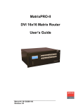


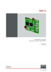
![Theater Management Software V5.6 [v06]](http://vs1.manualzilla.com/store/data/005786775_1-99bc430d529a8a144d04bed9ea0580b8-150x150.png)