1
Vocia®
CI1
Operation Manual
Biamp Systems 9300 SW Gemini Drive Beaverton, Oregon 97008, U.S.A. (503) 6417287 www.biamp.com
IMPORTANT SAFETY INSTRUCTIONS
1) Read these instructions.
10) Protect the power cord from being
walked on or pinched particularly at
plugs, convenience receptacles, and the
point where they exit from the apparatus.
2) Keep these instructions.
3) Heed all warnings.
4) Follow all instructions.
11) Only use attachments/accessories
specified by the manufacturer.
WARNING - To reduce the risk of fire or
electric shock, do not expose this
apparatus to rain or moisture.
12) Use only when secured or supported
by equipment rack, cart or table designed
to provide adequate mechanical strength,
heat dissipation and securement to the
building structure.
The apparatus shall not be exposed to
dripping or splashing and no objects filled
with liquids, such as vases, shall be
placed on the apparatus.
6) Clean only with dry cloth.
When a cart is used, use
caution when moving the
cart / apparatus combination
to avoid injury from tip-over.
7) Do not block any ventilation openings.
Install product in accordance with the
manufacturer’s instructions.
13) Unplug this apparatus during
lightning storms or when unused for long
periods of time.
8) Do not install near any heat sources
such as radiators, heat registers, stoves,
or other apparatus (including amplifiers)
that produce heat.
14) Refer all servicing to qualified service
personnel. Servicing is required when the
apparatus has been damaged in any way,
such as power-supply cord or plug is
damaged, liquid has been spilled or
objects have fallen into the apparatus,
the apparatus has been exposed to rain
or moisture, does not operate normally,
or has been dropped.
5) Do not use this apparatus near water.
CAUTION – Installation of the apparatus
should be made by a qualified installation
person and should conform to all
applicable local codes.
Modifications and optional equipment
information referenced in this manual is
for use by qualified installation and
service personnel only.
Explanation
of
safety
related
symbols which appear on the outside
of the apparatus.
Product labeling and the operation
manual may use the internationally
recognized symbols defined below to note
safety messages.
WARNING – Class I Safety Grounding
This apparatus employs Class I Safety
Grounding and must be connected to a
MAINS socket with a protective eathing
connection.
Lightning Bolt: Hazardous
Live voltages present when
this unit is in operation. Do
not touch terminals marked
with this symbol while the unit
is connected to live power.
Disconnect Device - The MAINS plug is
used to disconnect MAINS power and
must remain readily operable.
9) Do not defeat the safety purpose of
the grounding-type plug. A grounding
type plug has two blades and a third
grounding prong. The third prong is
provided for your safety. If the provided
plug does not fit into your outlet, consult
an electrician for replacement of the
obsolete outlet.
Exclamation Point: Replace
components (i.e. fuses) only
with the values specified by
the manufacturer. Failure to
do so will compromise safe
operation of this unit.
2
TABLE OF CONTENTS
CI1 CONTROL INTERFACE . . . . . . . . . . . . . . . . . . . . . . . . . . . . . . . . . . . . . . . . . . . . . . 4
Features . . . . . . . . . . . . . . . . . . . . . . . . . . . . . . . . . . . . . . . . . . . . . . . . . . . . . . . . . . . . . . . . . . . . . . . . . . . . . . . . . . . . . . 4
Setup and Use . . . . . . . . . . . . . . . . . . . . . . . . . . . . . . . . . . . . . . . . . . . . . . . . . . . . . . . . . . . . . . . . . . . . . . . . . . . . . . . . . 4
FRONT PANEL . . . . . . . . . . . . . . . . . . . . . . . . . . . . . . . . . . . . . . . . . . . . . . . . . . . . . . . . 5
Local Sounder . . . . . . . . . . . . . . . . . . . . . . . . . . . . . . . . . . . . . . . . . . . . . . . . . . . . . . . . . . . . . . . . . . . . . . . . . . . . . . . . .
Local Sounder Silence Switch . . . . . . . . . . . . . . . . . . . . . . . . . . . . . . . . . . . . . . . . . . . . . . . . . . . . . . . . . . . . . . . . . . . .
System Test Switch . . . . . . . . . . . . . . . . . . . . . . . . . . . . . . . . . . . . . . . . . . . . . . . . . . . . . . . . . . . . . . . . . . . . . . . . . . . . .
System Fault Reset Switch . . . . . . . . . . . . . . . . . . . . . . . . . . . . . . . . . . . . . . . . . . . . . . . . . . . . . . . . . . . . . . . . . . . . . . .
5
5
5
5
REAR PANEL . . . . . . . . . . . . . . . . . . . . . . . . . . . . . . . . . . . . . . . . . . . . . . . . . . . . . . . . 67
Fire Detection System (CIE) Connections . . . . . . . . . . . . . . . . . . . . . . . . . . . . . . . . . . . . . . . . . . . . . . . . . . . . . . . . . .
Connections from External Devices for Fault Indications. . . . . . . . . . . . . . . . . . . . . . . . . . . . . . . . . . . . . . . . . . . . . .
Connections to LSI16. . . . . . . . . . . . . . . . . . . . . . . . . . . . . . . . . . . . . . . . . . . . . . . . . . . . . . . . . . . . . . . . . . . . . . . . . . .
Power Supply Connections . . . . . . . . . . . . . . . . . . . . . . . . . . . . . . . . . . . . . . . . . . . . . . . . . . . . . . . . . . . . . . . . . . . . . .
6
7
7
7
INSTALLATION . . . . . . . . . . . . . . . . . . . . . . . . . . . . . . . . . . . . . . . . . . . . . . . . . . . . . . . . . 8
SPECIFICATIONS . . . . . . . . . . . . . . . . . . . . . . . . . . . . . . . . . . . . . . . . . . . . . . . . . . . . . . . 9
WARRANTY . . . . . . . . . . . . . . . . . . . . . . . . . . . . . . . . . . . . . . . . . . . . . . . . . . . . . . . . . . 10
EU DECLARATION . . . . . . . . . . . . . . . . . . . . . . . . . . . . . . . . . . . . . . . . . . . . . . . . . . . . . .11
EU ROHS COMPLIANT . . . . . . . . . . . . . . . . . . . . . . . . . . . . . . . . . . . . . . . . . . . . . . . . . 12
3
CI1 CONTROL INTERFACE
The CI1 Control Interface is a companion product to the Vocia® LSI16 Life Safety Interface. It facilitates the necessary connections to the LSI16 for standards compliance. Features
!" High reliability switches for Local Sounder Silence, System Test and System Fault Reset
!" High level sounder for Fault/Alarm warning
!" Dual power summing with power loss fault connection
!" Provides terminating resistors for Alarm and Fault Inputs
!" Provides terminating resistors for any unused monitored outputs
!" Current limited reference voltage output
!" Rack mountable (1RU)
!" CE marked and RoHS compliant
!" Covered by Biamp Systems’ warranty
Setup and Use
#"$%&'"()*+,()-"./"01%&'2"34("45)(.6,4/7"89,:)"69)"01%&'2"()*+,()-";4/<=+(.6,4/",/">4;,."-436?.()@"."$%&'"()*+,()-"4/:A"./",/6)(;4//);6,4/"
with an LSI16 as detailed below. Once the required interconnections have been established, the CI1 will operate with the LSI16 to provide the necessary functionality. It is recommended that the CI1 be mounted immediately adjacent to an LSI16 so the CI1 controls can be associated with indications on the LSI16.
Vocia installations designed to comply with the requirements of EN 5416 must be installed in accordance with Biamp recommendations detailed in this User Manual and in the Vocia VACIE Reference Guide (download from www.biamp.com).
4
FRONT PANEL
The CI1 has three switches on the front panel and an internal (local) sounder, audible through the panel.
Local Sounder
B9)":4;.:"-4+/C)(";4DD)/;)-"?9)/)E)("./A".:.(D",/5+6"();),E)-"./")F6)(/.:"-,=/.:"3(4D"69)"<()"C)6);6,4/")*+,5D)/6@";4/6(4:"./C"
indicating equipment (CIE) or equivalent. It will also commence when any fault is detected. The sounder will continue until the alarm or fault is reset.
Local Sounder Silence Switch
If the local sounder is operating, this switch may be used to silence it. The alarm or fault condition that caused the sounder to operate is unaffected by operating this switch. If a new alarm or fault is detected, the sounder will restart. Press and hold the switch for two seconds to operate.
System Test Switch
B9,-"-?,6;9"?,::",/,6,.6)"."6)-6"-)*+)/;)"4/"69)"01%&'27"#::",/C,;.64(-",/"+-)"4/"69)"01%&'2"?,::":,=96"G(,)HA"./C"69)"-4+/C)(",/"69)"$%&'"?,::"
-4+/C"G(,)HA@"69+-";4/<(D,/="69.6")--)/6,.:".//+/;,.64(-".()"3+/;6,4/.:7"I()--"./C"94:C"69)"-?,6;9"34("6?4"-);4/C-"64",/,6,.6)"69)"6)-6"
sequence.
System Fault Reset Switch
A System Fault denotes that the LSI16 cannot guarantee correct operation of the Vocia system in an emergency mode. It is indicated on the LSI16 and by the sounder in the CI1. A system fault can only be cleared by operating the System Fault Reset switch. Note that when the LSI16 is powered up, the System Fault will be operational until the System Fault Reset switch is pressed. Press and hold the switch for two seconds to reset a System Fault.
5
REAR PANEL
There are four main interconnection paths to the rear panel:
!" $4//);6,4/-"64"69)"<()"C)6);6,4/"-A-6)D"J$%KLM
!" Connections from external devices for fault indications
!" Connections to the LSI16
!" Power supply connections
Each of these connection paths has several circuits as detailed below.
Fire Detection System (CIE) Connections
B9)-)";,(;+,6-".()"5(4E,C)C"4/"6?4"<E)&54-,6,4/"5:+=&,/"G.((,)("-6(,5";4//);64(-7"B9)"
Isolated Ground provides a circuit return that is not directly connected to the CI1 and LSI16 Ground. #:.(D"%/5+6-"'"69(4+=9"N".()"-,=/.:-"3(4D"69)"<()"C)6);6,4/"-A-6)D7"B9)-)"-,=/.:-"
5:.;)"69)">4;,."-A-6)D",/64")D)(=)/;A"D4C)".;;4(C,/="64"69)";4/<=+(.6,4/"
determined for the input in Vocia software. The Alarm Reset Input cancels all active alarms in the system while the Alarm Silence Input maintains all active alarms but causes emergency messages to be silenced. The CI1 provides the necessary terminating resistors for each input. Inputs are asserted by a positive transition to 1224V with respect to the ‘Isolated Ground’ connection. This transition should preferably be derived from a dry contact closure to a remote 12V24V source, or to the CI1 24V Reference Out (see below).
B9)">4,;)"#:.(D"#;6,E)"4+65+6",-"5(4E,C)C"64"-,=/.:"64"69)"<()"C)6);6,4/"-A-6)D"69.6"
the Vocia system has been activated in emergency mode in response to an Alarm Input. A constant output denotes that an emergency message is playing. A pulsed output (1.25Hz) indicates that an alarm is active but emergency messages have been silenced.
B9)"O)/)(.:"P.+:6"Q+65+6",-"5(4E,C)C"64"-,=/.:"64"69)"<()"C)6);6,4/"-A-6)D"69.6"69)()"
is a fault in the Vocia system that could affect delivery of an emergency message.
Connector
Label
Function
Isolated Ground
A1
Alarm 1 Input from CIE
A2
Alarm 2 Input from CIE
A3
Alarm 3 Input from CIE
A4
Alarm 4 Input from CIE
Rs
Alarm Reset Input from CIE
Si
Alarm Silence Input from CIE
VA
Ground
Voice Alarm Active Output to CIE
GF
General Fault Output to CIE
The Voice Alarm Active and General Fault outputs pull low (to ground) when active. The outputs are monitored by the LSI16 for opencircuit or shortcircuit to ground or power supply and for overvoltage on the output pin (>35V DC). If incorrect conditions are detected a Fault is signaled. Output monitoring 3.;,:,6.6)-";4D5:,./;)"?,69"E4,;)")E.;+.6,4/"-6./C.(C-7"P4("D4/,64(,/="5+(54-)-".":4.C"JD.F,D+D"RRSTL"D+-6"G)";4//);6)C"G)6?))/"
each output and a positive voltage source referenced to the LSI16 Ground, at the far end of the connection to the CIE (i.e. at the CIE). #/"0KU",/C,;.64(";4//);6)C"69(4+=9"."()-,-64("64"."54-,6,E)"E4:6.=)".6"69)"$%K"?,::"-+3<;)".-"."D4/,64(,/=":4.C7"
V46)"69.6"69)"01%&'2"5(4E,C)-"."'W>"-4+(;)".6"69)"X'W>"Q+6Y"6)(D,/.:"4/"69)"01%&'27"Q+65+6-"D.A"G)"5+::)C"+5"64"69,-"-4+(;)M"94?)E)("69)"
total current drawn from the source must not exceed 100mA. If an external voltage source is used for the outputs, it must not exceed 35V DC and in addition to the output loads, must also be connected to the LSI16 ‘External Supply Overvoltage Monitor’ input (refer to LSI16 User Manual) for monitoring purposes. Due to monitoring constraints, it is not possible to use both the LSI16 internal 10V source and an external source. 6
REAR PANEL
Connections from External Devices for Fault Indications
B9)-)";,(;+,6-".()"5(4E,C)C"4/"."-,/=:)"<E)&54-,6,4/"5:+=&,/"G.((,)("-6(,5";4//);64(7"#::"
Inputs are fully isolated from the CI1 and LSI16 internal circuits. The Isolated Ground provides a circuit return that is not directly connected to the CI1 and LSI16 Ground. These inputs allow the signaling of faults from external devices to the Vocia system so it may indicate and log faults that could affect emergency operation. These fault signals are typically derived from contact closures on external devices. For multiple devices (e.g. Multiple UPS units), fault contacts from each device may be ‘wiredOR’ connected (connected in parallel) to the fault input. UPS fault inputs are typically derived from UPS units used in the system (e.g. for backup powering of VA8600 units). PSU fault inputs are typically derived from batterybacked power supplies used to power parts of a Vocia system. EWS PSU fault inputs are derived from optional emergency microphones (EWSx) to indicate loss of power supply. Ethernet fault inputs are derived from fault contacts of industrial Ethernet switches used in critical parts of a Vocia system.
Connector
Label
Function
Isolated Ground
U
UPS Fault
P
PSU Fault
W
EWS PSU Fault
E
Ethernet Fault
All fault inputs are asserted by connecting the relevant pin to Isolated Ground. The UPS Fault, PSU Fault and EWS PSU Faults must be ;4//);6)C"64"RN>"?9)/"/4/&.--)(6)C"),69)("GA"C,();6";4//);6,4/"4("69(4+=9"5+::&+5"()-,-64("JD.F,D+D"R7RSTL7"B9)"RN>"()3)()/;)"E4:6.=)"
output on the power supply connector may be used for this purpose. The Ethernet Fault input is pulledup internally and does not need an external pullup.
Connections to LSI16
B9)-)";,(;+,6-".()"5(4E,C)C"4/"34+("JNL"<E)&54-,6,4/"./C"4/)"J'L"69())&54-,6,4/"5:+=&,/"G.((,)("-6(,5";4//);64(-"5:+-"."U$"G.(():"Z.;S7" K.;9";4//);64(":.G):",-"5()<F)C"GA"[B4"01%&'2\]"$4//);64(-".()":4;.6)C"-4"69.6"?,69"69)"$%&'"D4+/6)C"C,();6:A".G4E)"4("G):4?"69)"01%&'2@ circuit connections may be made by directly connecting pinforpin to the vertically adjacent connector. Short interlinking cables are provided with the CI1 for this purpose. Refer to the LSI16 Operation Manual for the circuit functions of these connectors.
Note that the LSI16 PSU Fault, Protection Fault and Path Fault outputs are connected to the CI1 purely for the purpose of providing required monitoring resistors (these outputs are not otherwise used by the CI1). If these outputs are required for remote fault indications, the relevant connections should be removed from the Monitored Outputs connector of the LSI16. As described in the LSI16 Operation Manual, and external monitoring resistor will be required if these circuits are so used.
Power Supply Connections
B9)-)";,(;+,6-".()"5(4E,C)C"4/"."-,/=:)"<E)&54-,6,4/"5:+=&,/"G.((,)("-6(,57"%/5+6-"
are provided for two 24V power supply circuits to drive the LSI16. This facilitates standards compliance by providing a means of redundant connections.
Each power supply must be capable of 24V DC at 15Watts. The Ground 1 and Ground 2 connections are internally connected together and to system ground. The VRef connection may be used as a voltage source for pullups on required fault inputs. This output is current limited at 100mA.
Loss of power to either power supply input will result in the LSI16 detecting a fault. If standards compliance is not required for an installation, a single power supply connection must be paralleled to the two power supply inputs to avoid generating a fault signal.
7
Connector
Label
Function
Ground 1
1
24 Volts DC Input 1
Ground 2
2
VRef
24 Volts DC Input 2
24 Volts Reference Out
INSTALLATION
The CI1 requires one rack space 1.75 inches (44.45mm) high and 19 inches (483mm) wide with 10 inches (254mm) depth. Mounting the unit using four screws with washers will prevent marring of the front panel. PVC or nylon washers are appropriate.
Please install the unit away from heat sources, such as vents and radiators, and in rooms with adequate ventilation. Ensure that air can circulate freely behind, beside, and above the unit. Do not exceed the maximum ambient operating temperature of 32113 degrees F (045°C).Beware of conditions in an enclosed rack that may cause the temperature to exceed ambient room conditions.
Note: To operate correctly, the CI1 requires an accompanying LSI16 plus connections to external components and devices as described in this manual.The CI1 should be mounted in close proximity to the accompanying LSI16.
For EN 5416 compliance, refer to the Vocia VACIE Reference Guide which details mandatory installation requirements.
8
SPECIFICATIONS
Control Interface 1 SPECIFICATIONS
Alarm Inputs:
Dimensions:
Assertion:
Transition from 0V to 12-24V
Fault Inputs:
Assertion:
Transition from +V to 0V
Maximum pull-up resistor:
Height:
1.75 inches (44.45mm)
Width:
19 inches (483mm)
Depth:
10 inches (254mm)
Weight:
2.2k
Approx 6.4lbs (2.8kg)
Ambient Operating Temperature:
Outputs:
32-113°F (0-32°C)
Compliance:
Assertion:
FCC Part 15, class B
Low
Pull-up Load:
CE marked
max 22k
Max. external supply:
EN 54-16 certified
35V
Max. continuous current:
RoHS Directive
350mA
Current Limit:
UL 60065 Listed, E215636
800mA
Power:
C-UL Listed, E215636
2 x 24V, 15Watts each
C-Tick, N24138 (Australia)
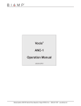
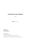
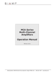
Control Interface 1 BACK PANEL
BIAMP SYSTEMS
10
Designed in Australia
Assembled in USA
0832-CPD-1401
CIE (Fire Detection System)
A1 A2 A3 A4
Rs Si
Fault Inputs
VA GF
P
N24138
52SJ
To LSI-16 Monitored Outputs
UE
W
5
6
7 4 8 10V
3
To LSI-16
System Fault
To LSI-16 Control Inputs
2
1
3
4 2
1 5
6
7
C NC NO
8
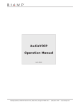
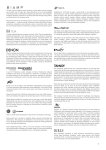
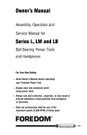
Control Interface 1 BLOCK DIAGRAM
Silence
Test
Reset
1
Power
In
Σ
2
Alarm/Fault Sounder
24VDC
CIE
Fault Inputs
9
To LSI-16
Switches
To LSI-16
24V
Input
2 x 24V
15W Class 2 or LPS
Model CI-1
Power Supply
1
2
Vref. 24V 100mA
CI1 WARRANTY
BIAMP SYSTEMS IS PLEASED TO EXTEND THE FOLLOWING 5YEAR LIMITED WARRANTY TO THE ORIGINAL PURCHASER OF THE PROFESSIONAL SOUND EQUIPMENT DESCRIBED IN THIS MANUAL
1. BIAMP Systems warrants to the original purchaser of new products that the product will be free from defects in material and workmanship for a period of 5 YEARS from the date of purchase from an authorized BIAMP Systems dealer, subject to the terms and conditions set forth below.
2 If you notify BIAMP during the warranty period that a BIAMP Systems product fails to comply with the warranty, BIAMP Systems ?,::"()5.,("4("()5:.;)@".6"_%#`I"1A-6)D-Y"456,4/@"69)"/4/;4/34(D,/="5(4C+;67""#-".";4/C,6,4/"64"();),E,/="69)"G)/)<6-"43"69,-"?.((./6A@"
you must provide BIAMP Systems with documentation that establishes that you were the original purchaser of the products. Such evidence may consist of your sales receipt from an authorized BIAMP Systems dealer. Transportation and insurance charges to and from the BIAMP Systems factory for warranty service shall be your responsibility.
a7""B9,-"?.((./6A"?,::"G)">Q%U",3"69)"-)(,.:"/+DG)("9.-"G))/"()D4E)C"4("C)3.;)CM"4(",3"69)"5(4C+;6"9.-"G))/".:6)()C@"-+GZ);6)C"64" C.D.=)@".G+-)"4("()/6.:"+-.=)@"()5.,()C"GA"./A"5)(-4/"/46".+694(,b)C"GA"_%#`I"1A-6)D-"64"D.S)"()5.,(-M"4(",/-6.::)C",/"./A"
manner that does not comply with BIAMP Systems’ recommendations.
4. Electromechanical fans, electrolytic capacitors, gooseneck microphones, cords connecting handheld microphones, harddrives, displays, and normal wear and tear of items such as paint, knobs, handles, keypads and covers are not covered under this warranty. All serverbased devices are warranted for 3 years only. 5. This warranty is in lieu of all other warranties, expressed or implied. Biamp Systems disclaims all other warranties, expressed or ,D5:,)C@",/;:+C,/=@"G+6"/46":,D,6)C"64@",D5:,)C"?.((./6,)-"43"D)(;9./6.G,:,6A"./C"<6/)--"34("."5.(6,;+:.("5+(54-)7
6. The remedies set forth herein shall be the purchaser’s sole and exclusive remedies with respect to any defective product. 7. No agent, employee, distributor or dealer of Biamp Systems is authorized to modify this warranty or to make additional warranties on behalf of Biamp Systems. Statements, representations or warranties made by any dealer do not constitute warranties by Biamp Systems. Biamp Systems shall not be responsible or liable for any statement, representation or warranty made by any dealer or other person.
8. No action for breach of this warranty may be commenced more than one year after the expiration of this warranty.
c7""_,.D5"-A-6)D-"-9.::"/46"G)":,.G:)"34("-5);,.:@",/C,();6@",/;,C)/6.:@"4(";4/-)*+)/6,.:"C.D.=)-@",/;:+C,/=":4-6"5(4<6-"4(":4--"43"+-)"
arising out of the purchase, sale, or use of the products, even if BIAMP Systems was advised of the possibility of such damages.
012011_585.0279.90A
10
COMPLIANCE
!
DoC VCI201006!
!
!
EC Declaration of Conformity
Biamp Systems Corporation, as manufacturer having sole responsibility, hereby
declares that the following described product complies with the applicable provisions of
the DIRECTIVES below except as noted herein. Any alterations to the product not
agreed upon and directed by Biamp Systems Corporation will invalidate this declaration.
Product Model:
Vocia® CI-1
Product Description:
Control Interface
Applicable EC Directives:
Applicable Harmonized Standards:
LVD Directive (2006/95/EC)
Safety
EN 60065:2002
EMC Directive (2004/108/EC)
Emissions
Immunity
EN 55103-1:1996, Environment E2
EN 55103-2:1996
Special Considerations for Product Environment or Compliance:
Use only CE and “LPS” marked 24 VDC External Power Adaptor.
Shielded cabling must be used for system connections.
Technical Construction File, Location and Contact:
Biamp Systems Corporation
9300 S.W. Gemini Drive
Beaverton, OR USA 97008
phone:
fax:
e-mail:
(503) 641.7287
(503) 626.0281
[email protected]
Authorized Representative:
Larry Copley, Compliance Engineer
Authorized Signature:
Issued:
June 2010!
11
COMPLIANCE
EU RoHS COMPLIANT
This Biamp product, including all attendant cables and
accessories supplied by Biamp, meets all requirements of EU
Directives 2002/95/EC of January 27, 2003, and 2005/618/EC
of August 18, 2005, the EU RoHS Directives. An EU RoHS
Materials Content Declaration document may be obtained at
www.biamp.com
!
(This information is presented to comply with the requirements of Chinese law SJ/T11363-2006)”
!"#$%
Biamp Systems Corporation
&'()*+ (Remote Control Device)
Vocia CI-1
*+89!(Equipment Chassis)!
Pb
2
X
Hg
3
O
:;<=>?@ (Plug-in Terminal Blocks)
AB(CD ROM)
CDEFGHIJK (Manual and Paper Documents)
LM9EN!LMOP (Box and Packing Materials)
O
O
O
O
O
O
O
O
./01
!"!#$$,-%
Cd
Cr+6
PBB
4
567
X
O
O
O
O
O
O
O
O
O
O
O
O
O
O
PBDE
O
O
O
O
O
0Q%RS./N!T$OPUVWX!Y!"#$Z[ SJ/T11363-2006 V\)]^.
XQ%RS./U_`!aXT$OPNbVWX!Y!"#$c[ SJ/T11363-2006 V\)]^.
defgEh,ij4NbVT$OPUk4lFmn#Vbopqrs 0.01%ktuvwx 91/338/EEChyzuvwx
76/769/EECi\){|E}~•€•‚#$E)ƒ.„UN…†V~‡ˆ‰
dqŠaX,‹X#$NbVT$OPUk2lFmn#Vbopqrs 0.1%:
1) e@-Œ/U•Ž•NbV2
2) 2d•OU‘’“aXn”-•kbop– 0.35%
3) 2d—OU‘’“aXn”-•kbop– 0.4%
4) 2d˜OU‘’“aXn”-•kbop– 4%
5) c™š›œPUV2h•2Pn”k2bors 85%i
6) e@žŸ./•V2
7)
¡Xq¢-•£¤VœPUNbV2k~[¥=¦§E¨©ªŒLMkFU
2Vbors 80% tZ[ 85%
8) «¬¦¥=-®•V2
9) &'()*'+,¯-().°±²³´¤/0¥123œPU4
!
dµ¶}~·¸ŠkU¹º»}~¼\“ 10 ½k¾/‘Q
!"º¿ÀÁ“ 0-40C (32-104°F)
!"ÂÁ“ 0-95%kÃÄÅ
!"Æ;cÁ“ 0-10,000 ÇÈ
!"ÉÊËÌÍÎ
!"Ï!Ð,FGѱÒÓÔÕ./
!"eÖ“ 24 Vdc LPS
!"./Ï!×Øh×Ø./¬Ù•Úªi
!" ÛÜÝÞßà}~áâVOPÒãN!äÚ
!
12