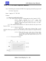
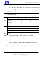
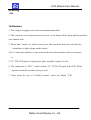
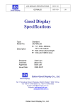
1
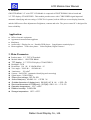
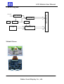
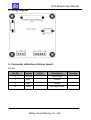
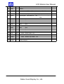
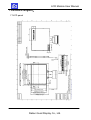
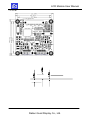
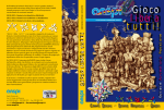
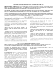
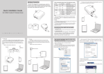
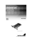
LCD MODULE SPECIFICATIONS
SPEC NO
GD25TTD
REV NO
Good Display
Good Display
Specifications
Type:
Model No.
Description:
Prepared:
Checked:
Approved:
Issue Date:
Standard
GD25TTD
2.5”, 240 x RGB x 320 dots, ,
TFT LCD module.
With white LED backlight
VIDEO/CVBS input.
Xiaoli Lan
Moon Wu
Boris Jen
2009.02.19
Dalian Good Display Co., Ltd.
Good Display
No.17 Gonghua Street, Shahekou District, Dalian 116021 China
Tel: +86-411-84619565 Fax: +86-411-84619585
E-mail: [email protected]
Website: www.good-lcd.com
www.good-lcd.com.cn
Dalian Good Display Co., Ltd.
RD001
LCD Module User Manual
Catalogue
Content
2
Version
3
1.Profile
4
2. Application
4
3. Main parameter
4
4. Block diagram, product picture
5
5. Wiring diagram
6
6. Connector definition of driver board
6-8
7. Structural diagram
9-10
8. 2.5"TFT- LCD Panel Inspection standard
11-12
9. Packing method
13
10.Attention
13
Dalian Good Display Co., Ltd.
LCD Module User Manual
Version
Date
2009-2-19
version
RD001
content
The First Version
Dalian Good Display Co., Ltd.
LCD Module User Manual
1. Profile:
GD25TTD RD001 2.5" color TFT LCD Module is composed of JD25TTD RD001 driver board and
2.5" TFT display: GTO025THEG1. This module provides users with CVBS/VIDEO signal input and
automatic identifying and converting of NTSC/PAL systems, built-in OSD (on-screen display) function,
and the OSD menu offers adjustment of brightness, contrast and color. The power control IC is designed for
better reliability.
Application:
●
●
●
●
●
Office electronic equipment
Apparatus & measurement appliance
Machinery
Audiovisual(Display for car、Portable DVD player、Long-distance terminal player)
Home appliance(Video door phone、Video telephone, Digital Camera)
3. Main Parameter:
z Product name:2.5" TFT-LCD module
z Module Model :GD25TTD RD001
z TFT display:2.5" TFT LCD display: GTO025THEG1
z Backlight:LED
z Resolution:320(H)X 3(RGB) X240(V)
z View angle(U/D/L/R):(20/50/40/40)
z Luminance: 250 cd/m2
z System:PAL/NTSC (automatic identifying and converting)
z Signal input: CVBS/VIDEO
z Power input voltage:DC 5V-15V
z Active Area(mm):49.946(H)×37.56(V)
z Outside dimension of display(mm):56.2(W)×47.8(H)×2.53(D)
z Structural dimension of PCBA(mm):50.0(W)×50.0(H)×7.9(D)
z Operation temperature:-10℃~+60℃
z Relative humidity:5~95% RH
z Storage temperature:-20℃~+70℃
Dalian Good Display Co., Ltd.
LCD Module User Manual
4. Block diagram:
DC TO DC
DC TO DC
key
MCU
CVBS
OSD
Video decode
Module Picture:
Dalian Good Display Co., Ltd.
Color tft lcd module
5V-15V
LCD Module User Manual
5. Wiring diagram:
6. Connector definition of driver board:
6.1 J4
Pin No.
Symbol
In/Out
Discription
1
5V-15V
I
Power input
2
GND
-
Ground
3
GND
-
Ground
4
CVBS
I
Video signal input
Dalian Good Display Co., Ltd.
Remark
LCD Module User Manual
6.1 J2
Pin No.
Symbol
In/Out
Description
1
GND
-
Ground
2
DOWN
I
Key -
3
UP
I
Key +
4
MENU
I
menu
5
ON/OFF
I
Power switch
6
+5V
O
+5V output
Remark
6.3 J101
Pin
Symbol
I/O
Description
1
CP3
C
Capacitor for power setting
2
CP4
C
Capacitor for power setting
3
CP5
C
Capacitor for charge pump
4
CP6
C
Capacitor for charge pump
5
CP7
C
Capacitor for charge pump
6
CP8
C
Capacitor for charge pump
7
DUMMY
--
Dummy
8
DUMMY
--
Dummy
9
PCD
C
10
VCOML
C
11
VCOMH
C
Capacitor for VCOM high
12
AGND
--
Analog ground
13
DUMMY
--
Dummy
14
AVDD
C
Regulation capacitor for analog voltage
15
CP1
C
Capacitor for charge pump
16
CP2
C
Capacitor for charge pump
17
PWM
O
18
FB
I
19
LED-
--
LED power: cathode
20
DUMMY
--
Dummy
21
DUMMY
--
Dummy
Remark
Capacitor for pre-charge data signal
Capacitor for VCOM
high
low
Power transistor gate signal
for the boost converter
Main boost regulator feedback
input.
Dalian Good Display Co., Ltd.
Note 1
LCD Module User Manual
22
LED+
--
LED power: anode
23
GND
--
Ground
24
VCC
--
25
VSYNC
I
26
HSYNC
I
27
DCLK
I
Clock signal,
28
DIN0
I
Data
input
29
DIN1
I
Data
input
30
DIN2
I
Data
input
31
DIN3
I
Data
input
32
DIN4
I
Data
input
33
DIN5
I
Data
input
34
DIN6
I
Data
input
35
DIN7
I
Data
input
36
SDA
I/O
Serial
interface data
37
SCL
I
Serial
interface clock
38
SCEN
I
Serial
interface chip enable
39
SHDB
I
40
GREST
I
Note 1
Power supply for digital
Vertical
sync
Horizontal
circuit and charge pump circuit
input. Negative polarity
sync
input. Negative polarity
latch data onto
Shutdown
line
latches at the rising
edge
line
line
line
input
System reset pin
Dalian Good Display Co., Ltd.
Note 2:
LCD Module User Manual
7.Structural diagram:
7.1LCD panel
Dalian Good Display Co., Ltd.
LCD Module User Manual
7.2 PCB
Dalian Good Display Co., Ltd.
LCD Module User Manual
8. 2.5" TFT- LCD PANEL Inspection standard:
Aim:Establishing the standard of PANLE for inspecting material & progress and
for clients’ inspection.
Scope:Apply to 2.5″ TFT LCD
Content:
8.1. Inspection standard and method:
8.1.1. The method and determinant of inspecting the nick of panel of LCD:
8.1.1.1. Inspect vertically (or at 45 ° angle from
left/right)under the light tube (the power is 20 W) in the
distance of 30cm to the panel. If there is no nick , it is “OK”.
Otherwise “NG”.
8.1.2. The method and determinative for black & white & color spots for the
Panel of LCD:
8.1.2.1. Inspection methods
8.1.2.1.1. Black spots:under status of denote light,set the
MASK of black spot inspection near the black spot then compare the big and small by
eyes.
8.1.2.1.2. White & Color spots: under status of denote light,
set the Mask of black spot inspection on the white
spot(or color spot) then inspect them by eyes if it
can hide.
8.1.2.2. Division of LCD Panel
Dalian Good Display Co., Ltd.
LCD Module User Manual
Remark: A1:The center of the available area for the picture
A2:The edge of the available area for the picture(around the central
area)
8.1.3. Determinant Choice
Allowed Area
Spot Diameter(mm)
A1
A2
Black d≤0.15
Irrespective
Irrespective
Spot
0.15<d≤0.3
4
4
0.3<d≤0.5
2
3
0.5d>0.8
0
2
White d≤0.15
Irrespective
Irrespective
or
0.15<d≤0.3
3
3
color
0.3<d≤0.5
1
2
spot
0.5d>0.8
0
1
Remark: 1. Size: Average Diameter=(Max. Diameter + Min. Diameter)/2
2. Using information above as a standard in order to judge while the spot
are dense.
3. Black & White spot:To judge the obvious spots through the change
of voltage by comparison。
4. Total quantity of Black & white & color spot: A1+A2 ≤ 4。
Dalian Good Display Co., Ltd.
LCD Module User Manual
9.Packing
TBD
10.Attention:
1. The voltage of supply power don't exceed maxmium limit.
2. The connector can’t connect board in reverse, or the board will be burnt and the products
can't funtion well.
3. Please don’t touch it in order to keep your skin non-burn when you electrify the
board(there is high voltage on the board).
4. It is a electronic product, so you need to take anti-static measure when you operate
it.
5. 2.5” TFT-LCD panel is a glasswork, place carefully ,broken for fear.
6. The connection is “FPC”, which connect 2.5” TFT-LCD panel with PCB, Please
operate it carefully in order to keep it well.
7. Don't touch the pin of "variable resistor" when you adjust "VR".
Dalian Good Display Co., Ltd.