1
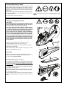
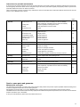
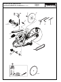
Instruction Manual
Original Instruction Manual
EK6100
EK6101
Important:
Read this instruction manual carefully before putting the Power Cut into operation and strictly observe the
safety regulations!
Keep this instruction manual!
Thank you for purchasing a MAKITA product!
Table of contents
Congratulations on choosing a MAKITA Power Cut cutoff saw!
Like our chain saws, the MAKITA Power Cuts feature specially designed high-performance engines with outstanding
power-to-weight ratios, for heavy-duty yet lightweight tools.
Packing ................................................................................ 2
Delivery inventory .............................................................. 3
Symbols ............................................................................... 3
Other advantages of the MAKITA Power Cuts:
SAFETY PRECAUTIONS
Intended use ................................................................... 4
General precautions ....................................................... 4
Protective equipment ...................................................4-5
Fuels / Refuelling ............................................................ 5
Putting into operation ...................................................... 5
Cutting discs ................................................................... 6
Kickback and lock-in ....................................................... 7
Working behavior / Method of working ............................ 7
Always observe the following when using
synthetic resin cutting discs ............................................. 8
Cutting metal ................................................................... 8
Cutting masonry and concrete .....................................8-9
Transport and storage ..................................................... 9
Maintenance ................................................................. 10
First aid ......................................................................... 10
Disposal and environmental protection ......................... 10
• Sturdy construction and high reliability.
• Maintenance-free electronic ignition, hermetically sealed to
protect against dust and moisture.
• Vibration damping with the MAKITA 2-mass system (D2M) for
tireless working even when guiding the Power Cut by hand.
• Multilevel air Þlter system with turbo-cyclone Þlter for dependable function even under very dusty conditions.
• The Featherlight-Start system lets you start the cutter effortlessly with a spring-loaded starting assist.
• Extensive range of resin-bonded and diamond grit cutting
discs.
The following industrial property rights apply:
DE 202010000143 U1, DE 202011050393 U1, DE 202011050396
U1, DE 202011050394 U1, DE 202010004275 U1, DE
202009010557 U1, DE 202009006860 U1, DE 202008003781
U1.
We want you to be satisÞed with your MAKITA product.
In order to guarantee the optimal function and performance of
your Power Cut and to ensure your personal safety we would
request you to perform the following:
Read this instruction manual carefully before putting the
Power Cut into operation for the Þrst time, and strictly
observe the safety regulations! Failure to observe these
precautions can lead to severe injury or death!
EU Conformity Declaration
The undersigned, Tomoyasu Kato, as authorized by MAKITA
Corporation, declare that the MAKITA machines,
Type: 315
Power Cut EK6100, EK6101
manufactured by MAKITA Corporation, 3-11-8 Sumiyoshi-Cho,
Anjo, Aichi, 446-8502 Japan, conforms to the basic safety and
health requirements of the applicable EU Directives:
EU Machinery Directive 2006/42/EG, EU EMC Directive
2004/108/ EG, Outdoor Noise Directive 2000/14/EG.
Page
Technical data ................................................................... 11
Denomination of components ......................................... 12
PUTTING INTO OPERATION
Mounting the cutting disc ............................................... 13
Fuels / Refuelling .....................................................14-15
Starting the engine ........................................................ 16
Cold-starting ................................................................. 16
Warm-starting ............................................................... 16
Stop engine ................................................................... 16
Adjusting the carburetor .................................................. 17
MAINTENANCE
Changing the V-belt ...................................................... 18
Cleaning the protection hood ........................................ 19
Cleaning / changing the air Þlter ................................... 19
Replacing the spark plug .............................................. 20
Checking the ignition spark ............................................ 20
Replacing the suction head .......................................... 20
Replacing the starter cable ........................................... 21
Replacing the return spring ........................................... 22
Replacing the start spring ............................................. 22
Instructions for periodic maintenance ........................... 23
Service, spare parts and guarantee ...........................23-24
Troubleshooting ............................................................... 25
SPECIAL ACCESSORIES
Diamond cutting discs, water tank ................................. 25
Extract from spare parts list .......................................26-27
The most important standards applied to properly meet the requirements of the above EU Directive were: EN 19432, CISPR
12, EN ISO 14982, DIN EN 61000-4.
The conformity assessment procedure 2000/14/EG was performed per Annex V. The measured noise level (Lwa) is 114
dB(A). The guaranteed noise level (Ld) is 115 dB(A).
The technical documentation is on Þle at MAKITA International
Europe Ltd., Michigan Drive, Tongwell, Milton Keynes, Bucks,
MK15 8JD, England.
Anjo, 20.8.2012 for MAKITA Corporation
Tomoyasu Kato
Managing Director
2
Packing
Your MAKITA Power Cut is packed in a cardboard box to prevent shipping damage.
Cardboard is a basic raw material and is consequently reuseable
or suitable for recycling (waste paper recycling).
Delivery inventory
5
4
3
2
1
1. Power Cut
2. Cutting disc (not in the general scope of delivery. Country-speciÞc)
3. Screwdriver (for carburetor adjustment)
4. Offset screwdriver
5. Universal wrench 13/19
6. Instruction manual (not shown)
In case one of the parts listed should not be included in the
delivery inventory, please consult your sales agent.
Symbols
You will notice the following symbols on the Power Cut and in the Instruction Manual:
Read instruction manual and
follow the warning- and safety
precautions!
Particular care and caution!
Never use circular saw blades!
Never use damaged cutting discs!
Forbidden!
Wear helmet and eye, respiratory
and hearing protection!
Wear protective gloves!
Combination switch
Choke, On/Stop
Safety position
Start engine
Wear respiratory protection!
Hazardous dust and/or
gas emission!
Stop engine!
Fire hazard from ßying sparks!
Warning!
Kickback!
No smoking!
Fuel and oil mixture
No open Þre!
First aid
Direction of cutting wheel rotation
Recycling
Warning: the max. peripheral
speed of the cutting disc is 80 m/s!
Cutting disc dimensions
CE - Marking
3
SAFETY PRECAUTIONS
Note: The illustrations in the safety precautions are not identical
with the product!
-
The helmet visor (B) protects the face from dust and material
grains. In order to prevent injuries to eyes and face, always
wear protective goggles (C) or visor when using the Power
Cut.
-
To prevent hearing damage, always wear suitable personal
hearing protection. (ear muffs (D), ear plugs, etc.). Octave
brand analysis upon request.
-
When dry-cutting dust-producing materials such as stone
or concrete, always wear approved respiratory protection
(E).
-
Work gloves (F) of tough leather are part of the required
work kit of the Power Cut and must always be worn when
working with the Power Cut.
Intended use
Power Cut
Use the Power Cut cutoff saw outdoors only, for trimming and cutting
suitable materials, using cutting discs rated for this machine.
Improper use:
Never use the cutoff saw cutting discs for grinding or sanding (using the side of the cutting disc to remove material). The disc can
break! Never use the Power Cut with saw blades, cutter blades,
brushes etc.
Unauthorised users:
Persons unfamiliar with the Instruction Manual, children, young
people, and persons under the inßuence of alcohol, drugs or medications must not use the Power Cut.
General precautions
-
The operator MUST read this instruction manual to ensure
safe operation (even if you already have experience in using cutoff saws). It is important to be familiar with the operation of this particular cutoff saw. Users insufÞciently informed
will endanger themselves as well as others due to improper
handling.
-
Let only persons who have experience in using cutoff saws work
with this unit. When letting another person use the Power Cut,
this instruction manual must be provided along with it.
-
First-time operators should ask a specialist to instruct them in
working with gasoline-powered cutoff saws.
-
Children and persons under 18 years of age must not be allowed
to use this Power Cut. Persons over the age of 16 years may,
however, use the Power Cut for the purpose of being trained as
long as they are under the supervision of a qualiÞed trainer.
-
Working with the Power Cut requires high concentration.
-
Operate the Power Cut only if you are in good physical condition.
If you are tired, your attention will be reduced. Be especially
careful at the end of a working day. Perform all work calmly and
carefully. The user has to accept liability for others.
-
Never work while under the inßuence of alcohol, drugs, medication or other substances which may impair vision, dexterity or
judgement.
-
A Þre extinguisher must be available in the immediate vicinity
when working in easily inßammable vegetation or when it has
not rained for a long time (danger of Þre).
-
Asbestos and other materials that can release toxins may be cut
only with the necessary safety precautions and after notiÞcation
of the proper authorities and under their supervision or that of
a person appointed by them.
-
The use of dust-reduction devices is urgently recommended
(see Accessories, pressure water tank, water tank).
Protective equipment
-
In order to avoid head, eye, hand or foot injuries as well as
to protect your hearing the following protective equipment
must be used during operation of the Power Cut:
-
The kind of clothing should be appropriate, i. e. it should be tightÞtting but not be a hindrance. Clothing in which grains of material
can accumulate (trousers with cuffs, jackets and trousers with
wide-open pockets, etc.) must not be worn, particularly when
cutting metal.
-
Do not wear any jewellery or clothing that can get caught or
distract from the operation of the Power Cut.
-
It is necessary to wear a protective helmet whenever working
with the Power Cut. The protective helmet (A) is to be checked
in regular intervals for damage and is to be replaced after 5
years at the latest. Use only approved protective helmets.
4
1
2
3
4
-
Always wear safety shoes or boots (G) with steel toes, non-skid
soles, and leg protectors when working with the Power Cut.
Safety shoes equipped with a protective layer provide protection
against cuts and ensure a secure footing.
-
Always wear a work suit (H) of tough material with sufÞcient
ßame-retardant qualities whenever working with the cutoff
saw.
Fuels / Refuelling
-
Go to a safe, level place before refuelling. Never refuel while
on scaffolding, on heaps of material, or in similar places!
-
Switch off the engine before refuelling the Power Cut.
-
Do not smoke or work near open Þres (6).
-
Let the engine cool down before refuelling.
-
Fuels can contain substances similar to solvents. Eyes and skin
should not come in contact with mineral oil products. Always wear
protective gloves when refuelling (not the regular work gloves!).
Frequently clean and change protective clothes. Do not breathe
in fuel vapors. Inhalation of fuel vapours can be hazardous to
your health.
-
Do not spill fuel. If a spill occurs, clean off the Power Cut immediately. Fuel should not come in contact with clothes. If your
clothes have come in contact with fuel, change them at once.
-
Ensure that no fuel oozes into the soil (environmental protection).
Use an appropriate base.
-
Refuelling is not allowed in closed rooms. Fuel vapors will accumulate near the ßoor (explosion hazard).
-
Ensure to Þrmly tighten the screw cap of the fuel tank.
-
Before starting the engine, move to a location at least 3 meters
(approx. 3 1/4 yards) from where you fuelled the Power Cut
(7), but not within the extended swing range of the cutting disc
(direction of sparks).
-
Fuel cannot be stored for an unlimited period of time. Buy only
as much as will be consumed in the near future.
-
When making up the gasoline/oil mixture, always put the oil in
the mixing container Þrst, and then the gasoline.
-
Use only approved and marked containers for the transport and
storage of fuel.
-
Keep fuel away from children!
5
6
3 meters
7
Putting into operation
-
Do not work on your own. There must be someone around
in case of an emergency (within shouting distance).
-
Observe all anti-noise regulations when working in residential
areas.
-
Never use the Power Cut near inßammable materials or
explosive gases! The Power Cut can create sparks leading
to Þre or explosion!
-
Make sure that all persons within 30 meters (33 yards), such
as other workers, are wearing protective gear (see "Protective
Equipment") (8). Children and other unauthorized persons must
remain more than 30 meters away from the working area. Keep
an eye out for animals as well (9).
-
Before starting work the Power Cut must be checked for
perfect function and operating safety according to the prescriptions. In particular, make sure that the cutting wheel is in
good condition(replace immediately if torn, damaged or bent),
the cutting wheel is properly mounted, the protective hood is
locked in place, the hand guard is properly mounted, the throttle
moves easily and the half-throttle lock button functions properly,
the grips are clean and dry, and the combination switch functions
properly (Start/Stop (I/O) switch, choke).
-
Start the Power Cut only after complete assembly and inspection. Never use the Power Cut when it is not completely assembled.
30 m
8
= wearing Protective Equipment
9
5
Cutoff discs
-
The protection hood must always be on! Change discs only
with the engine off!
- There are two basic types of cutoff discs:
- For metal (hot cutting)
- For masonry (cold cutting)
NOTE:
When using diamond cutoff discs, always make sure to observe
the "direction of rotation" markings. Diamond discs should only be
used for cutting masonry/brick/ concrete etc.
- Cutoff discs are intended only for radial loading, i.e. for cutting.
Do not grind with the sides of the cutting disc! This will break
the disc (10)!
Caution!
Never change direction (turning radius less than 5 meters /
5 1/2 yards), exert lateral (sideways) pressure, or tip the Power
Cut during cutting (11)!
- Use a cutting disc only for cutting the materials it is intended
for. The proper type of disc must be used, for either metals or
masonry.
- The arbor hole of the cutting disc must be an exact Þt with the
arbor or shaft. If the arbor hole is larger, it must be Þtted with an
adapter ring (available as an accessory).
- The cutting disc must be rated for freehand cutting at up to 4370
rpm or 80 m/sec for 350 mm discs, or up to 5100 rpm or 80 m/s
for 300 mm discs. Use only cutting discs that comply with EN
12413, EN 13236.
- The disc must be free of defects (12). Do not use defective cutting discs.
Always tighten the cutting disc mounting bolt to a torque of 30
Nm. Otherwise, the cutting disc can twist.
- Before starting the cutting disc, make sure you have a steady
footing.
- Put the Power Cut into operation only as described in this instruction manual (13). Always place your left foot in the rear handle
and grasp the other handle Þrmly (with thumb and Þngers). Other
starting methods are not allowed.
- When starting the Power Cut it must be well supported and
securely held. The cutting disc must not be touching anything.
- If the cutting disc is new, test it by running it at least 60 seconds
at top speed. When doing this, make sure that no persons or
body parts are in the extended swing range of the disc, in case
it is defective and ßies apart.
- When working with the Power Cut always hold it with both
hands. Take the back handle with the right hand and the tubular handle with the left hand. Hold the handles tightly with your
thumbs facing your Þngers.
- CAUTION: When you release the throttle lever the disc will
keep spinning for a short period of time (free-wheeling effect).
- Continuously ensure that you have a safe footing.
- Hold the Power Cut such that you will not breathe in the exhaust
gas. Do not work in closed rooms or in deep holes or ditches
(danger of poisoning by fumes).
- Switch off the Power Cut immediately if you observe any
changes in its operating behavior.
- Switch off engine before refuelling, changing the cutoff disc, work
breaks, transporting or moving the Power Cut, taking it out of
operation, or dealing with malfunctions. Before any maintenance
work, move the combination switch to the lock symbol (14).
- Turn off the engine immediately and check the disc if you hear
or feel any change in cutting behaviour.
- Turn off the Power Cut when taking a break or stopping work
(14). Place the unit in such a way that the disc is not touching
anything and cannot endanger anyone.
- Do not put the overheated Power Cut in dry grass or on any
inßammable objects. The mufßer is very hot (danger of Þre).
- IMPORTANT: After wet cutting, Þrst turn off the water feed and
then let the disc run at least 30 seconds, to ßing off the remaining
water and prevent corrosion.
6
10
min. 5 m
11
12
13
● Refuelling
● Changing cutoff discs
● Stopping work
● Transport
● Putting out of function
● Maintenance
14
Kickback and lock-in
-
-
-
-
-
When working with the Power Cut there is a danger of kickback
and lock-in.
Kickback occurs when the top of the cutting disc is used for
cutting (15).
This causes the Power Cut to be thrown back toward the user
with great force and out of control. Risk of injury!
To prevent kickback, observe the following:
Never cut with the section of the cutting disc shown in Þgure 15.
Be especially careful when reinserting the disc into cuts
that have already been started!
Lock-in occurs when the cut narrows (crack, or workpiece under
stress).
This causes the Power Cut to suddenly jump forward, out of
control and with great force. Risk of injury!
To prevent lock-in, observe the following:
When reinserting the disc into previous cuts, have the Power
Cut running at top speed. Always cut at top speed.
Always support the workpiece so that the cut is under tension
(16), so that the cut does not press together and jam the cutting
disc as it proceeds through the material.
When starting a cut, apply the disc to the workpiece with care.
Do not just shove it into the material.
Never cut more than one piece at a time! When cutting, make
sure that no other workpiece comes into contact.
15
Working behavior / Method of working
-
-
-
-
-
-
-
Before starting work, check the work area for any hazards
(electrical wires, inßammable substances). Clearly mark the
work area (for example with warning signs or by cordoning off
the area).
When working with the Power Cut hold it Þrmly by the front and
rear handles. Never leave the Power Cut unattended!
Use the Power Cut at high speed as far as possible (see “Technical Data”).
Only use the Power Cut during good light and visibility periods.
Be aware of slippery or wet areas, and of ice and snow (risk of
slipping).
Never work on unstable surfaces. Make sure that there are no
obstacles in the working area, risk of stumbling. Always ensure
that you have a safe footing.
Never cut above your shoulder height (17).
Never stand on a ladder to cut (17).
Never use the Power Cut while standing on scaffolding.
Do not lean over too far when working. When putting down and
picking up the Power Cut, do not bend over from the waist, but
instead bend in the knees. Save your back!
Guide the Power Cut in such a way that no part of your body
is within the extended swing range of the disc (18).
Use cutting discs only for the materials for which they are designed!
Use cutting discs only for the materials for which they are designed. Do not use the Power Cut to lift up and shovel away
pieces of material and other objects.
Important! Before cutting, remove all foreign objects, such as
rocks, gravel, nails etc. from the cutting area. Otherwise, such
objects can be ßung away by the disc with great speed. Injury
hazard!
When cutting workpieces down to length use a Þrm support.
If necessary, secure the workpiece from slipping, but do not
steady it with your foot or allow another person to hold it.
When cutting round items, always secure them against rotation.
16
17
18
7
When using synthetic resin cutting discs, always observe the following:
Cutting masonry and concrete
CAUTION:
Always wear approved respiratory protection!
-
Synthetic resin cutting discs can absorb moisture. This
moisture can cause the disc to become unbalanced at high
speed. This imbalance can cause the disc to break.
-
Do not cool resin cutting discs with water or other ßuids.
-
Do not expose resin cutting discs to high humidity or
rain!
Asbestos and other materials that can release toxic substances may be cut only after notifying the proper authorities
and under their supervision or that of a person appointed
by them. When cutting prestressed and reinforced concrete
piles, follow the instructions and standards of the responsible authorities or the builder of the structural member.
Reinforcement rods must be cut in the prescribed sequence
and in accordance with applicable safety regulations.
Do not use resin cutting discs past their use-by date (expiration date)! The date (quarter and year) is stamped on the disc’s
arbor ring.
EXAMPLE: 04 / 2013
This cutting disc can be used through the end of the fourth quarter
of 2013, if properly stored and correctly used.
IMPORTANT!
NOTE:
Mortar, stone, and concrete develop large quantities of dust during
cutting. To increase the lifetime of the cutting disc (by cooling),
to improve visibility, and to avoid excessive dust creation, we
strongly recommend wet cutting instead of dry cutting.
Cutting metals
IMPORTANT!
Always wear approved respiratory protection!
Materials that can release toxic substances may be cut only
after notifying the proper authorities and under their supervision or that of a person appointed by them.
CAUTION!
The rapid rotation of the cutting disc heats metal and melts it
at the point of contact. Swing the guard as far down as possible (19) in order to direct the stream of sparks forward, away
from the operator (Þre hazard).
-
Determine the cut line, mark the cut and apply the disc to the
material at moderate speed, to cut a guide groove before going
to top speed and applying more pressure to the Power Cut.
-
Keep the disc straight and vertical. Do not tip it, as this can
break it.
-
The best way to get a good, clean cut is to pull or move the
Power Cut back and forth. Do not simply press the disc into
the material.
-
Thick round stock is best cut in stages (20).
-
Thin tubing and pipes can be cut with a simple downward
cut.
-
Cut large-diameter pipes as for round stock. To prevent tipping
and for better control, do not let the disc sink too deeply into
the material. Instead, always cut shallow around the whole
piece.
-
Worn discs have a smaller diameter than new discs, so that at
the same engine speed they have a lower effective circumferential speed and therefore do not cut as well.
-
Cut I-beams and L-bars in steps; see Figure 21.
-
Cut bands and plates like pipes: along the wide side with a long
cut.
-
When cutting material under stress (supported material or material in structures), always make a notch in the thrust (pressure)
side, and then cut from the tension side, so that the disc does
not lock in. Secure cutoff material from falling!
19
20
CAUTION!
If there is a chance that the material is under stress, be prepared for it to kick back. Make sure you can get out of the
way if you have to!
Be particularly careful in scrap-metal yards, junkyards, at accident sites, and with haphazard piles of material. Precariously
balanced pieces or pieces under stress can act in unpredictable
ways, and may slide, jump out, or burst. Secure cutoff material
from falling! Always exercise extreme caution and use only
equipment that is in perfect working order.
Observe the accident-prevention rules and regulations of your
employer and/or insurance organization.
8
21
In wet cutting, the disc is wetted at an equal rate on both sides by
a trickle of water. MAKITA offers the right accessories for all wet
cutting applications (see also "SPECIAL ACCESSORIES").
-
Remove foreign objects such as sand, stones and nails found
within the working area. Caution: Watch out for electric wires
and cables!
The rapid rotation of the cutting disc at the point of contact
throws fragments out of the cut groove at high speed. For
your safety, swing the protection hood down as far as possible (23), so that material fragments are thrown forward,
away from the operator.
-
Mark the cut, and then make a groove about 5 mm (just under
1/5") along the entire length of the planned cut. This groove will
then guide the Power Cut accurately guring the actual cutoff.
-
Perform the cut with a steady back-and-forth motion.
-
When cutting slabs to size, you need not cut through the entire
material thickness (creating unnecessary dust). Instead, simply
make a shallow groove, and then knock off the excess material
cleanly on a ßat surface (25).
23
CAREFUL!
When cutting into lengths, cutting through material, making cutouts,
etc., always make sure to plan the direction and sequence of cuts
in such a way that the disc does not get jammed by the cut-off
piece, and that no persons can be injured by falling pieces.
Transport and storage
-
Always turn off the Power Cut when transporting it or
moving it from place to place on a site (26).
-
Never carry or move the unit with the engine on or the
disc moving!
-
Carry the unit only by the tubular (middle) handle with the cutting disc pointing behind you (26). Avoid touching the exhaust
mufßer (burn hazard!)
-
When moving the Power Cut over longer distances, use a
wheelbarrow or wagon.
-
When transporting the Power Cut in a vehicle, make sure it is
securely positioned in such a way that no fuel can leak out.
Always remove the cutting disc before transporting the unit in
a vehicle.
-
The Power Cut should be stored safely in a dry place. It must
not be left outdoors! Always dismount the cutting disc before
storage. Keep the Power Cut away from children.
-
Before long-term storage and before shipping the Power
Cut, follow the instructions in the chapter on "Periodic
care and maintenance". ALWAYS empty the fuel tank and
run the carburetor dry.
-
When putting cutting discs in storage, be careful to:
• Clean and dry them well. CAUTION: Do NOT clean synthetic
resin cutting discs with water or other ßuids!
• Store them lying down ßat.
• Avoid dampness, freezing temperatures, direct sunshine,
high temperatures and temperature ßuctuations, as these
can cause breakage and splintering.
• Before re-using a resin cutting disc, make sure of the use-by
(expiration) date (quarter and year, stamped on the arbor
ring). If this date has been exceeded, do NOT use the cutting
disc.
-
25
26
Always check new cutting discs or cutting discs that have
been in storage to make sure that they are free of defects
and before the Þrst cut test-run the tool at top speed for at
least 60 seconds. Keep body parts and people well away out
of range of the direction of the cutting disc during this test.
9
Maintenance
-
Before performing maintenance work switch off the Power
Cut (27) and pull out the plug cap.
-
Always check the Power Cut before using it to make sure that
it is in good working order. In particular, make sure that the
cutting disc is properly mounted. Make sure that the cutting
wheel is undamaged and suitable for the job it will be used
for.
-
Operate the Power Cut only at a low noise and emission level.
For this ensure the carburetor is adjusted correctly.
-
Clean the Power Cut regularly.
-
Check the fuel tank cap regularly for good sealing.
27
Observe the accident prevention instructions issued by
trade associations and insurance companies. NEVER
make any modiÞcations to the Power Cut! You will only
be putting your own safety at risk!
Perform only the maintenance and repair works described in
the instruction manual. All other work must be carried out by
MAKITA Service.
Use only original MAKITA spares and accessories.
The use of non-MAKITA spares, accessories, or cutting discs
increases the risk of accident. We cannot accept any responsibility for accidents or damage occurring in association with
the use of cutting discs or accessories other than original
MAKITA.
SERVICE
28
First aid
For the event of a possible accident, please make sure that a
Þrst aid kit is always immediately available close by. Immediately
replace any items used from the Þrst aid box.
When calling for help, give the following information:
- Place of the accident
- What happened
- Number of injured people
- Kind of injuries
- Your name!
NOTE
Individuals with poor circulation who are exposed to excessive
vibration may experience injury to blood vessels or the nervous
system.
Vibration may cause the following symptoms to occur in the Þngers, hands or wrists: ”Falling asleep” (numbness), tingling, pain,
stabbing sensation, alteration of skin colour or of the skin. If any
of these symptoms occur, see a physician!
Disposal and environmental protection
Be mindful of the environment!
Dispose of worn-out or defective cutting discs in accordance with
your local disposal regulations. To protect unusable cutting discs
from misuse, destroy them before disposal.
When the Power Cut is worn out or damaged beyond repair, have
it disposed of or recycled in an environmentally sound manner. If
necessary, consult your local authorities.
10
29
Technical data
Displacement
Bore
Stroke
Max. power / operating speed
Max. torque
Idling speed
Clutch engagement speed
Engine speed limitation
Max. spindle speed
Sound pressure level LpA, eq per EN 19432 1) 4) 6)
Sound power level LWA, eq per EN 19432 6) 7)
Vibration acceleration ahv, eq per EN 19432 1) 6)
- Tubular handle
- Rear handle
Carburetor (diaphragm carburetor)
Ignition system (with speed limitation)
Spark plug
Electrode gap
Fuel consumption at max. load per ISO 8893
SpeciÞc consumption at max. load per ISO 8893
Fuel tank capacity
Mixture ratio (fuel/two-stroke oil)
- when using MAKITA oil
- when using other oils (quality grade: JASO FC or ISO EGD)
- when using Aspen Alkylat (two-stroke fuel)
Cutting disc for 80 m/sec. 2)
Cutting disc for 80 m/sec. 2) 5)
Arbor diameter
V-belt
Overall weight (tanks empty, without cutting disc)
cm3
mm
mm
kW/1/min
Nm
1/min
1/min
1/min
1/min
dB(A)
dB(A)
m/s2
m/s2
Type
Type
Type
mm
kg/h
g/kWh
l
mm
mm
mm
no.
kg
EK6100
EK6101
60.7
47
35
3.2 / 9.500
3.9
2.600
3.900
9.850 ± 150
5.100
99,6 / KpA=2,5
108,6 / KWA=2,5
60.7
47
35
3.2 / 9.500
3.9
2.600
3.900
9.850 ± 150
4.400
99,6 / KpA=2,5
108,6 / KWA=2,5
3,0 / K=2
3,6 / K=2
2,7 / K=2
3,5 / K=2
ZAMA C3
electronic
NGK BPMR 7A
0.5
1.42
430
0.7
0.5
1.42
430
0.7
50:1
50:1
50:1 (2%)
300 / 20,0 / 5 3)
-20,0
965 300 501
8,5
50:1
50:1
50:1 (2%)
350 / 20,0 / 5 3)
350 / 25,4 / 5 3)
20,0
965 300 510
8,8
1)
Data apply to idle and rated speed operation at a ratio of 1/7 to 6/7.
Circumference speed at max. engine speed.
Outside diameter / arbor hole / thickness.
4)
At the workplace (at user's ear).
5)
Country-speciÞc.
6)
Uncertainty (K=).
7)
Data apply rated speed operation.
2)
3)
11
Denomination of components
3
4
5
6
2
7
1
13
10
9
8
11
12
14
15
25
24
16
23
IdentiÞcation plate (9)
Indicate when ordering spare parts
22
EK6101
21
2012 123456
Makita Corporation, Anjo, Aichi, Japan
Made in Germany
XXX.XXX.XXX
20
19
18
17
Serial number
Year of manufacture
Typ XXX
1
Handle
14
Air intake
2
Air Þlter cover
15
Fuel pump (Primer)
3
Tubular handle
16
Safety locking button
4
Protection hood
17
Throttle lever
5
Water set
18
Combination switch „Choke, On/Stop (I/O)”
6
Adjusting screw
19
Fuel tank Þll-level window
7
Hold opening
20
Starter housing with starter
8
Fuel tank with handle
21
Stand
9
IdentiÞcation plate
22
Mufßer
10
Tank cap (fuel)
23
Cutting disc
11
Carburetor adjustment opening
24
Disc bolt
12
Holder for combination tool and 1/2" hose
25
Spring washer
13
Starter grip
12
PUTTING INTO OPERATION
CAUTION:
Always turn off the engine and pull off the spark plug cap
before doing any work on the Power Cut! Always wear
protective gloves!
CAUTION:
Start the Power Cut only after complete assembly and
inspection.
For the the following work, use the assembly tools included
with delivery:
1. 13/19 AF combination wrench
2. Allen key
3. Carburetor adjustment screwdriver
Place the Power Cut on a stable surface and carry out the following assembly steps:
Sequence
Mounting the cutting disc
Inspect the disc for damage.
See SAFETY INSTRUCTIONS, Page 6.
Unscrew screw (9) and remove the spring washer (8).
Place the cutting disc (5) on the arbour (7).
NOTE: The arbor hole of the cutting disc must be an exact Þt
with the arbor or shaft.
For cutoff discs with 25.4 mm (1”) arbor holes, use the correct
size disc holder (supplied only with cutoff discs with 25.4 mm
(1”) arbor holes).
Make sure the cutting disc is installed so it turns in the right
direction, if a direction is marked on the disc.
11
10
Place the spring washer (8) on the arbour and insert the screw
(9) and tighten by hand.
8
Slowly turn the cutoff disc until a hole (11) in the V-belt pulley is
visible in the counter-holding opening (10) of the cutting arm.
Insert the Allen key (2) as far as it will go. The shaft is now
blocked.
Tighten the screw with the combination wrench (1).
2
1
NOTE: Tighten the screw Þrmly (30 ± 2 Nm), as otherwise
the cutting wheel may slip during cutting.
Remove the Allen key and combination tool.
13
Fuel
CAUTION:
This saw is powered by mineral-oil products (gasoline and
oil).
Be especially careful when handling gasoline.
Avoid all ßame or Þre. Do not smoke (explosion hazard).
Fuel mixture
This tool is powered by a high-performance air-cooled twostroke engine. It runs on a mixture of gasoline and two-stroke
engine oil.
The engine is designed for unleaded regular gasoline with a min.
octane value of 91 ROZ. In case no such fuel is available, you
can use fuel with a higher octane value. This will not affect the
engine.
50:1
Gasoline
50:1
OIL
+
1000 cm3
5000 cm3
(1 litre)
(5 litre)
20 cm3
100 cm3
20 cm3
100 cm3
10000 cm3
(10 litre)
200 cm3
200 cm3
In order to obtain an optimum engine output and to protect
your health and the environment use unleaded fuel only.
To lubricate the engine, use a synthetic oil for two-stroke aircooled engines (quality grade JASO FC or ISO EGD), which
has to be added to the fuel. The engine has been designed for
use of MAKITA high-performance two-stroke engine oil and a
mixture ratio of only 50:1 to protect the environment. In addition,
a long service life and reliable operation with a minimum emission
of exhaust gases are ensured.
MAKITA high-performance two-stroke engine oil is available in the
following sizes to suit your individual requirements:
100 ml
order number 980 008 606
1
order number 980 008 607
l
In case MAKITA high-performance two-stroke engine oil is not
available, it is urgently recommended to use a mixture ratio of
50:1 with other two-stroke engine oils (quality grade: JASO FC or
ISO EGD), as otherwise optimum operation of the engine cannot
be guaranteed.
It is not wise to add more engine oil than speciÞed
to ensure safe operation. This will only result in a
higher production of combus-tion residues which
will pollute the environment and clog the exhaust
channel in the cylinder as well as the mufßer. In addition, fuel consumption will rise and performance
will decrease.
The Storage of Fuel
Fuels have a limited storage life. Fuel and fuel mixtures
age through evaporation, especially at high temperatures. Aged fuel and fuel mixtures can cause starting
problems and damage the engine.
Purchase only that amount of fuel, which will be consumed over the next few months. At high temperatures,
once fuel has been mixed it should be used up in 6-8
weeks.
Store fuel only in proper containers, in dry, cool,
secure locations!
Caution: Do not use ready-mixed fuel from petrol stations.
The correct mixture ratio:
50:1
when using MAKITA high-performance two-stroke engine
oil, i. e. mix 50 parts gasoline with 1 part oil.
50:1
when using other synthetic two-stroke engine oils
(quality grade JASO FC or ISO EGD), i. e. mix 50 parts
gasoline with 1 part oil.
NOTE: For preparing the fuel-oil mixture Þrst mix the entire oil
quantity with half of the fuel required, then add the remaining
fuel. Thoroughly shake the mixture before Þlling it into the chain
saw tank.
Caution: Open the tank cap carefully, as pressure might have
built up inside!
14
AVOID SKIN AND EYE CONTACT
Mineral oil products degrease your skin. If your skin
comes in contact with these substances repeatedly and
for an extended period of time, it will desiccate. Various
skin deseases may result. In addition, allergic reactions
are known to occur.
Eyes can be irritated by contact with oil. If oil comes into
your eyes, immediately wash them with clear water. If your
eyes are still irritated, see a doctor immediately!
Refuelling
IMPORTANT:
FOLLOW THE SAFETY PRECAUTIONS!
Be careful and cautious when handling fuels.
The engine must be turned off and cooled down!
Carefully clean the area around the fuel-tank Þller neck to keep
dirt from getting in the tank.
Place the Power Cut on an even surface.
Unscrew the tank cap and Þll tank with fuel mixture. Take care
to avoid spilling.
Screw the tank cap back on hand-tight.
Clean screw cap and tank after refuelling. Never start or operate the Power Cut in the same place as it was fuelled!
If fuel gets on your clothing, change clothes immediately.
Fuel mixture
Starting the engine
if
necessary
3 Meter
CAUTION:
Observe the SAFETY INSTRUCTIONS on page 4 and 5!
Start the Power Cut only after complete assembly and
inspection!
Move at least 3m away from the place where you fuelled
the Power Cut.
Make sure you have a good footing, and place the Power
Cut on the ground in such a way that the cutting disc is
not touching anything.
15
2
2a
Move the protective hood (1) into the proper position for the
work you intend to do (see illustration).
1
The protective hood (1) can be moved between the stops in
both directions.
Note: A water supply line (from a pressurized water tank or
other source) is connected by the water set on the protective
hood. The water ßow rate can be adjusted with the adjusting
screw (2). Press the 1/2" hose into the holder (2a).
For a slower ßow, turn the adjusting screw clockwise.
For a faster ßow, turn it counter-clockwise.
Cold starting:
Grasp front handle Þrmly with one hand and press the Power
Cut against the ground.
Place left toe in the rear handguard.
Prime the fuel pump (4) by pressing it several times until you
can see fuel in the pump.
Move the combination switch (3) up (choke position). This also
actuates the half-throttle lock.
Pull starter handle smoothly and evenly, until you hear the
Þrst ignition (but max. 3-5 pulls).
CAUTION: Do not pull the starter cable more than about 50
cm/20” out, and let it back in slowly by hand.
Move the combination switch (3) to the central “ON” position.
Pull the starter handle smoothly and evenly again.
4
3
5
6
As soon as the engine is running, grasp the rear handle (the
safety lock button (5) is actuated by the palm of the hand) and
press the throttle trigger (6). The half-throttle lock will disengage
and the engine will now idle.
Warmstart:
As described above for cold starting, but before starting push
the combination switch (3) up (Choke position) and
then right away back to the middle “ON” position. This is only
to engage the half-throttle lock. If the engine doesn’t start after
2 or 3 pulls, repeat the entire starting procedure as described
for cold starting.
NOTE: If the engine was switched off only for a short time, the
saw can be started without using the combination switch.
Important: If the fuel tank has been completely emptied and the
engine has stopped due to lack of fuel prime the fuel pump (4) by
pressing it several times until you can see fuel in the pump.
Cold start (Choke)
Warm start (ON)
Stopping the engine
Engine off
NOTE: After being pressed down, the combination switch will
revert to the ”ON” position again. The engine is switched off,
but can be turned on again without moving the combination
switch.
Combination switch in safety position
(ignition current cut off, necessary for all
maintenance, repair, and installation work)
16
Depress the combination switch
(3).
IMPORTANT: To cut off the ignition current, push the combination switch all the way down past the resistance point to the
safety position (
).
Adjusting the carburetor
NOTE: The grinding parts are equipped with an electronic
ignition to limit the speed.
At the factory the idling speed has been set to approx.
2600 rpm, but the running-in process of a new engine may
require slight readjustment of the idling speed.
Adjustments to the adjusting screws (L) and (H) may only
be made by an authorised MAKITA service centre.
7
For correct adjustment of the idling speed the following
steps must be carried out:
T
Start the engine and run it until it is warm (about 3 - 5
minutes).
L
Adjust the carburetor with the screwdriver (7, Order No. 944
340 001) included with the Power Cut. It has a lug that helps
with adjustment.
Readjust the idling speed.
If the cutoff disc turns when the engine is idling, turn the throttle
stop screw (T) counter-clockwise in small increments until the
disc no longer turns.
If the engine suddenly stops in idle, turn the screw back slightly
clockwise.
Switch off the engine.
MAINTENANCE
CAUTION:
Before doing any work on the Power Cut turn off the engine,
remove the cutting disc, pull the plug cap off the spark plug
and wear protective gloves!
CAUTION:
Start the Power Cut only after complete assembly and
inspection.
17
IMPORTANT:
Because many of the parts and assemblies not mentioned
in this Instruction Manual are vital to the safety of the
unit, and because all parts are subject to a certain amount
of wear and tear, it is important for your own safety that
you have the unit checked and maintained regularly by a
MAKITA service center.
IMPORTANT:
SERVICE
If the cutting wheel breaks during cutting, the
Power Cut must be repaired by a MAKITA service
centre before being used again!
Changing the V-belt
Loosen bolts (1) and remove belt cover (2).
1
2
Move the V-belt pulley into the position shown.
Insert the Allen key into the hole (3) to block the V-belt pulley
(5).
Note: Make sure that the V-belt pulley remains blocked.
Use the combination tool to turn the nut (4) about one turn
counter-clockwise.
Use the combination tool to turn the eccentric (6) forcefully
counter-clockwise to the position shown.
Remove the old V-belt (7) or belt fragments.
5
Clean out the interior with a brush.
Insert a new V-belt.
Use the combination tool to turn the eccentric (6) forcefully
clockwise to its original position (V-belt is now tight).
4
Tighten the nut (4).
Remove Allen key from hole (3).
3
Put the belt cover (2) on and tighten the bolts (1).
7
6
18
Note: The V-belt is highly elastic, so it is not necessary to
retighten it.
A worn V-belt causes the cutoff disc turns at the lowest idle
speed. In this case, the V-belt must be replaced!
Cleaning the protection hood
Over time, the inside of the protective hood can become caked
with material residue (especially from wet cutting), which if
allowed to accumulate can hinder the free rotation of the cutting disc. For this reason the hood must be cleaned out from
time to time.
Take off the cutting wheel with spring washer and remove the
accumulated material from inside the hood with a strip of wood
or similar implement.
NOTE: To install the cutting wheel see ”Mounting the cutting
wheel”.
Clean the shaft and all removed parts.
Cleaning / changing the air Þlter
CAUTION:
Turn off the engine before cleaning the air Þlter! Never clean
out the air Þlter with compressed air! Do not use fuel to
clean the air Þlter insert (3) and inner Þlter (6).
The service life of the engine depends on the condition
and regular maintenance of the Þlter elements. Failure
to perform maintenance and cleaning at the prescribed
intervals will cause increased wear inside the engine!
If the air Þlter becomes damaged, replace immediately!
Pieces of cloth or large dirt particles can destroy the engine!
Do not work in dusty conditions when it can be avoided!
The Þne dust generated when dry-cutting concrete and
stone is hazardous to the health of the operator and also
shortens the service life of the engine. Whenever possible,
wet-cut with water when working in concrete and stone,
to bind the dust.
Loosen both bolts (1) and remove the Þlter cover (2).
7
Take the air Þlter cover (3) out of the cover (5).
Loosen the six bolts (4) on the cover and remove the cover.
2
Remove the inner Þlter (6).
When reassembling, make sure that the two lugs (7) of the
Þlter cover engage in the cover (5).
1
Inner Þlter
Wash out the dirty inner Þlter (6, Order No. 315 173 020) in
lukewarm soapy water with regular dishwashing liquid.
Let the inner Þlter dry thoroughly.
3
Air Þlter insert (paper cartridge)
The air Þlter insert (3, Order No. 315 173 010) Þlters the intake
air through a very Þne paper Þlter lamella system. For this
reason the cartridge must never be washed or cleaned with
compressed air. Clean the air Þlter insert once per month.
4
5
To clean the air Þlter insert, spread it out slightly and carefully
tap it against a clean surface.
Replace the air Þlter insert every 500 operating hours. Replace it immediately if there is a drop in power, drop in speed,
or smoke in the exhaust.
Before installing the Þlter system, check the intake opening to
make sure no dirt particles have fallen in. If they have, remove
them.
6
19
Replacing the spark plug
1
CAUTION:
Do not touch the spark plug or plug cap if the engine is
running (high voltage).
Switch off the engine before starting any maintenance
work.
A hot engine can cause burns. Wear protective gloves!
The spark plug (Order No. 965 603 021) must be replaced in
case of damage to the insulator, electrode erosion (burn) or if
the electrodes are very dirty or oily.
Remove the Þlter cover and hood. See Cleaning / changing
the air Þlter.
Pull the plug cap (1) off the spark plug. Use only the combination
wrench supplied with the saw to remove the spark plug.
CAUTION: To prevent damage to the decompression valve
(8), when unscrewing the spark plug position the combination tool in such a way that it does not impact the valve.
Electrode gap
The electrode gap must be 0.5 mm.
CAUTION: Use only NGK BPMR 7A
spark plug.
Other spark plugs can damage the
ignition system!
Checking the ignition spark
Insert the combination tool (2) between the ventilation hood and
cylinder only as shown in the illustration.
4
CAUTION!
Do not insert the combination tool into the spark plug hole,
but make contact only with the cylinder (otherwise you may
damage the engine).
Using insulated pliers, hold the spark plug (3) (unscrewed but
with the plug cap on) against the combination tool (away from
the spark plug hole!).
3
2
Switch the combination switch (4) to ”ON”.
Pull the starter cable hard.
If the function is correct, an ignition spark must be visible near
the electrodes.
Replacing the suction head
The felt Þlter (5) of the suction head can become clogged. It
is recommended to replace the suction head once every three
months in order to ensure unimpeded fuel ßow to the carburetor.
Unscrew the tank cap (6), pull the retainer out of the opening.
Empty fuel tank.
Use a wire hook to pull the suction out of the tank opening for
replacement.
Caution: Do not allow fuel to come into contact with skin!
20
5
6
0,5 mm
Replacing the starter cable
Unscrew four screws (1).
Remove fan housing (2).
Insert a small screwdriver through the ventilation slit on the back
of the fan housing (2) near the holder (15).
Bend the air guide tab (4a) slightly to the side and carefully
remove the air guide (3) from the fan housing.
CAREFUL! Injury hazard! Do not unscrew screw (7) if the
return spring is under tension.
If the starter cable is to be replaced although it is not broken,
it will be necessary to Þrst de-tension the cable drum return
spring (13).
To do this, use the grip to pull the cable all the way out of the
fan housing.
Hold the cable drum with one hand, and with the other push the
cable into the space (14).
1
2
Carefully let the drum turn until the return spring is no longer
under tension.
7
Unscrew screw (7) and remove the carrier (8).
16
Remove any pieces of old line and take out the spring (6).
8
14
Carefully remove the cable drum (5).
Put the spring (6) back in the cable drum (so that its lower end
Þts in the notch, see the arrow in the close-up).
6
Thread a new cable (dia. 3.8 mm, length 1000 mm) as shown
in the illustration (don’t forget the washer (10)) and knot both
ends as shown.
11
Pull the knot (11) into the cable drum (5) and press it into the
space.
5
Pull knot (12) into the starter grip (9).
Put the cable drum and spring back on, and turn it slightly until
the return spring catches.
Guide the hole (16) in the carrier (8) over the end of the spring,
press down the carrier and turn it slightly counter-clockwise until
it is ßush on the cable drum.
4
Insert screw (7) and tighten.
3
Guide the cable into the slot (14) on the cable drum and turn
the drum with the cable clockwise three times.
Hold the cable drum with your left hand and with your right hand
untwist the cable, pull it tight and hold it.
Carefully release the cable drum. The spring will wind the cable
around the drum.
Repeat the procedure once. The starter grip should now stand
straight up on the fan housing.
NOTE: With the cable pulled all the way out, it must still be
possible to turn the pulley another 1/4 turn against the return
spring.
CAUTION: Danger of injury! Secure the cable grip when
pulled out! It will whip back if the cable pulley is released
by accident.
1
13
Mounting the fan housing
Insert the air guide (3) in the fan housing so that the Þve recesses (4) engage.
2
Position the fan housing on the machine, apply slight counterpressure, and pull the starter grip until the starter mechanism
engages.
12
15
Tighten screws (1).
9
10
21
Replacing the return spring pack/Replacing the
starter spring
Remove the fan housing (see “Replacing the starter cable”).
Remove the air guide from the fan housing (see “Replacing
the starter cable”).
Detension the return spring on the cable drum and remove the
cable drum (see “Replacing the starter cable”).
Note: Unspool the starter cable from the drum only. Do not pull
it out of the cable drum or the starter grip!
7
CAREFUL! Injury hazard! The return spring can pop out!
Always wear eye protection and protective gloves!
8
Lightly tap the fan housing on a wooden surface with the entire
surface of the hollow side, and hold it down. Now lift the fan
housing carefully and in small steps. This will allow the return
spring pack (13), which should now have fallen out, to relax in
a controlled manner if the return spring has popped out of the
plastic pack.
6
5
If the return spring pops out, it can be wound back into the
cassette as shown (15). Make sure the direction of winding is
correct.
Carefully insert a new return spring cassette and press down
until it engages.
Put the cable drum (5) and spring back on, and turn it slightly
until the return spring catches.
13
Put on the carrier (8) and bolt it on with bolt (7).
Tension the return spring (see “Replacing the starter cable”).
4
3
Replacing the starter spring
NOTE: If the spring (6) in the Featherlight-Starting system is
broken, more effort will be required to start the engine and you
will notice some resistance when pulling the starter cable.
If you notice this, check the spring (6) and replace if necessary.
1
Mounting the fan housing
Insert the air guide (3) in the fan housing so that the Þve recesses (4) engage.
Position the fan housing on the machine, apply slight counterpressure, and pull the starter grip until the starter mechanism
catches.
Tighten screws (1).
15
22
Instructions for periodic maintenance
To ensure long life, prevent damage and ensure the full functioning of the safety features the following maintenance must be performed regularly. Guarantee claims can be recognized only if this work is performed regularly and properly. Failure to perform the
prescribed maintenance work can lead to accidents!
Users of the Power Cut must not perform any maintenance work not described in this Instruction Manual. All such work must be
carried out by a MAKITA service centre.
Page
General
Entire Power Cut
Clean exterior, check for damage. In case of damage,
have repaired by a qualiÞed service centre immediately
Cutting disc
Inspect regularly for damage and wear.
Clutch
Have inspected at a service center.
Protection hood
Clean
19
Cutting disc
Inspect for damage and make sure the cutting wheel is
right for the job
6
Protective hood
Adjust position
16
Combination switch,
Safety locking button,
Throttle lever
Functional check
Functional check
Functional check
16
Tank cap
Check for tightness
Every day
Idle speed
Check (cutting disc must not turn on idle)
17
Every week
Starter housing
Clean to ensure proper air cooling
12
Starter cable
Check for damage
21
V-belt
Inspect for damage and wear
18
Spark plug
Check and replace if necessary
20
Mufßer
Check tightness of mounting
12
Screws and nuts
Check their condition and that they are Þrmly secured.
Before each start
6
Monthly
Air Þlter insert
Clean, replace after 500 operating hours
19
Every 3 months
Suction head
Replace
20
Fuel tank
Clean
Annually
Entire Power Cut
Check at an authorized service centre
Storage
Entire Power Cut
Clean exterior, check for damage. In case of damage,
have repaired by a qualiÞed service centre immediately
Cutting disc
Remove and clean
Fuel tank
Empty and clean
Carburetor
Run empty
13
Service, spare parts and guarantee
Maintenance and repair
The maintenance and repair of modern cutoff saws and their safety-related components requires qualiÞed technical training and a
workshop equipped with special tools and testing devices.
We therefore recommend that you consult a MAKITA service centre for all work not described in this instruction manual.
The MAKITA service centres have all the necessary equipment and skilled and experienced personnel, who can work out cost-effective
solutions and advise you in all matters.
To Þnd your local distributor, please visit www.makita-outdoor.com
23
Spare parts
Reliable long-term operation, as well as the safety of your Power Cut, depend among other things on the quality of the spare parts
used. Use only original MAKITA parts, marked
Only original parts are from the same production line as the original unit and therefore ensure the highest possible quality of materials, dimensions, functioning and safety.
Only original spare parts and accessories guarantee the highest quality in material, dimensions and function.
Original spare parts and accessories can be obtained from your local dealer. He will also have the spare part lists to determine the
required spare part numbers, and will be constantly informed about the latest improvements and spare part innovations.
Please bear in mind that if parts other than original MAKITA spare parts are used, this will automatically invalidate the MAKITA
product guarantee.
We will furthermore not accept any liability damages arising from the use of non-MAKITA spare parts.
Guarantee
MAKITA guarantees the highest quality and will therefore reimburse all costs for repair by replacement of damaged parts resulting
from material or production faults occurring within the guarantee period after purchase. Please note that in some countries particular
guarantee conditions may exist. If you have any questions, please contact your salesman, who is responsible for the guarantee of
the product.
Please note that we cannot accept any responsibility for damage caused by:
•
Disregard of the instruction manual.
•
Non-performance of the required maintenance and cleaning.
•
Incorrect carburetor adjustment.
•
Normal wear and tear.
•
Obvious overloading due to permanent exceeding of the upper performance limits.
•
The use of other than original MAKITA cutting discs.
•
Use of force, improper use, misuse or accidents.
•
Damage from overheating due to dirt on the fan housing.
•
Work on the Power Cut by unskilled persons or inappropriate repairs.
•
Use of unsuitable spare parts or parts which are not original MAKITA parts, insofar as they have caused the damage.
•
Use of unsuitable or old oil.
•
Damage related to conditions arising from lease or rent contracts.
•
Damages caused by disregarding loose outer bolted connections.
Cleaning, servicing and adjustment work is not covered by the guarantee. All repairs covered by the guarantee must be performed
by a MAKITA service centre.
24
Troubleshooting
Malfunction
System
Observation
Cause
Cutting disc does not
start turning
Clutch
Engine runs
Damage to clutch
Cutting disc runs in idle
Carburetor,
clutch
Cutting disc runs
Incorrect idle speed,
blocked clutch
Engine does not start or
only with difÞculty
Ignition system
Ignition spark
Malfunction in fuel supply system, compression system, mechanical malfunction.
No ignition spark
Switch on STOP, fault or short-circuit in the
wiring, plug cap or spark plug defective.
Fuel supply
Fuel tank is Þlled
Choke in wrong position, carburetor defective,
suction head dirty, fuel line bent or interrupted.
Compression
system
Inside
Cylinder base packing ring defective, radial
shaft packings defective, cylinder or piston rings
defective
Outside
Spark plug does not seal.
Mechanical
malfunction
Starter does not engage
Spring in starter broken, broken parts
inside the engine.
Warm start difÞculties
Carburetor
Fuel tank is Þlled
Wrong carburetor adjustment.
Ignition spark
Engine starts, but
dies immediately
Fuel supply
Fuel tank is Þlled
Wrong idling adjustment, suction head or
carburetor dirty.
Tank venting defective, fuel line interrupted,
cable defective, STOP switch defective.
Decompression valve dirty
InsufÞcient power
Several systems
may be involved
simultaneously
Engine is idling
Air Þlter dirty, wrong carburetor adjustment,
mufßer clogged, exhaust channel in cylinder
clogged.
V-belt
Belt has insufÞcient tension, V-belt is worn
SPECIAL ACCESSORIES
Diamond cutting discs
Pressurized water tank
MAKITA diamond cutting discs meet the highest demands
in working safety, ease of operation, and economical cutting performance. They can be used for cutting all materials
except metal.
To keep down dust and for better cutting-disc cooling, MAKITA
offers several options for wetting the disc during operation.
The high durability of the diamond grains ensures low wear
and thereby a very long service life with almost no change in
disc diameter over the lifetime of the disc. This gives consistent
cutting performance and thus high economy. The outstanding
cutting qualities of the discs make cutting easier.
The pressurized water tank is connected to the Power Cut by
the water set on the protective hood.
See “Accessories” for order number.
The metal disc plates give highly concentric running for minimal
vibration during use.
The use of diamond cutting discs reduces cutting time signiÞcantly. This in turn leads to lower operating costs (fuel
consumption, wear on parts, repairs, and last but not least
environmental damage).
25
Extract from the spare parts list
Use only original MAKITA parts. For repairs and
replacement of other parts, see your MAKITA service centre.
EK6100
EK6101
17
14
15
16
9
8
5
6
22
26
18
19
Extract from the spare parts list
Use only original MAKITA parts. For repairs and
replacement of other parts, see your MAKITA service centre.
Pos. MAKITA-No.
Qty.
EK6100
EK6101
Denomination
1
966 121 150
966 141 150
966 144 150
1
1
1
Synthetic resin cutting disc
Cutting disc for steel, dia. 300/20 mm
Cutting disc for steel, dia. 350/20 mm
Cutting disc for steel, dia. 350/25,4 mm
1
966 121 120
966 141 120
966 144 120
1
1
1
Cutting disc for masonry, dia. 300/20 mm
Cutting disc for masonry, dia. 350/20 mm
Cutting disc for masonry, dia. 350/25,4 mm
22
966 244 632
1
Cutting disc for masonry, dia. 350/25,4 mm
3
4
5
6
8
9
10
11
12
13
14
15
16
994 290 250
965 300 501
965 300 510
963 601 122
315 114 350
315 173 020
315 173 010
395 405 000
965 603 021
395 164 010
181 164 010
181 163 050
181 163 080
181 163 090
1
1
1
1
1
1
1
1
1
1
1
1
1
1
Hex screw M8x25
V-belt (EK6100)
V-belt (EK6101)
Suction head
Tank cap, compl. (fuel)
Inner Þlter
Air Þlter insert (paper cartridge)
Disk 5
Spark plug
Starter cable ø 3,8x1000 mm
Starter grip
Return spring in housing
Spring
Driver
17
18
19
941 719 131
940 827 000
944 340 001
1
1
1
Universal wrench SW 13/19
Offset screwdriver T27
Screwdriver (carburetor)
Diamond cutting disc
Accessories (not delivered with the Power Cut)
22
966 . . . . . .
1
Diamond cutting disc
Please consult your MAKITA dealer!
26
-
957 802 600
949 000 035
1
1
Pressure water tank, cpl.
Combined can (for 5l fuel, 2.5l oil)
27
To Þnd your local distributor, please visit
www.makita-outdoor.com
MAKITA Corporation
3-11-8 Sumiyoshi-Cho
Anjo, Aichi
446-8502 Japan
SpeciÞcations subject to change without notice
Form: 995 704 531 (2012-10 GB)