1
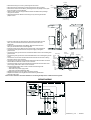
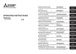
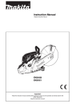
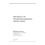
REMOTE WALL CONTROL INSTALLATION INSTRUCTIONS
WARNING – To reduce the risk of Þre, electric shock and injury to persons, the Remote Wall Control must be
installed only with Faber range hood models INCA PRO 30 RB or INCA PRO 38 RB, that are marked to indicate
suitability with this product. Other models cannot be used
READ AND SAVE THESE INSTRUCTIONS.
The Installer must leave these instructions with the homeowner.
The homeowner must keep these instructions for future reference and for local electrical inspectors’ use.
WARNING
Risk of electrical shock. Electrical wiring must be done by qualiÞed personnel in accordance with all applicable codes and standards. Turn
off the power and lock out the service panel before installing, wiring, or servicing this product. To prevent serious injury from electrical
shock or damage to electrical components - MAKE SURE POWER IS OFF! This unit must be grounded.
WARNING
TO REDUCE THE RISK OF FIRE, ELECTRIC SHOCK OR INJURY TO PERSONS, OBSERVE THE FOLLOWING:
a. Installation Work And Electrical Wiring Must Be Done By QualiÞed Person(s) In accordance With All Applicable Codes and Standards,
Including Fire-Rated Construction.
b. When cutting or drilling into wall or ceiling, do not damage electrical wiring and other hidden wires.
MAKE YOUR CUT-OUTS.
WARNING
• Cut a level 4 11/32” X 3 5/32” hole in to your desired location.
• Route the electrical cable from the hood to the wall control location.
INSTALL THE REMOTE WALL CONTROL
WARNING – To reduce the risk of Þre and electric shock, do not use this
control in an insulated wall
• Remove the back metalic panel of the Remote Wall Control by removing the four
screws.
• Insert and Þx a cable with four wires (Brown, Black, Red and Green Ground Wire)
into the knockout hole of the back metalic panel.
• Connect the green ground wire from the cable to the green ground screw.
• Connect the red wire from the cable to the red Remote Wall Control wire with a
twist-on wire connector.
• Connect the brown wire from the cable to the white/black Remote Wall Control
wire with a twist-on wire connector.
• Connect the black wire from the cable to the two black Remote Wall Control wires
with a twist-on wire connector.
• Replace the back metalic panel.
The twist on wire connector should be suitable for connecting multiple wires of different sizes
together.
• Remove the faceplate from the Remote Wall Control by removing two screws.
• Position the remote control box in a hole so that both face plate mounting tabs are ßush to the
Þnished wall surface. Fasten it to a wall stud using four screws (not supplied)
• Reinstall the control faceplate, ensuring not to pinch the wires.
CONNECTION OF THE REMOTE WALL CONTROL TO THE RANGEHOOD
To install the rangehood, please refer to the hood installation instructions.
• Remove the grease Þlters USING TWO HANDS one to hold the Þlter so that it doesn’t fall on
cooktop and one to turn the knob by pulling the knob out and turning to the left.
• Remove the entire bottom of the rangehood by pushing your thumbs into the side holes and
pulling the sides free from the rangehood.
black wiring
Y/G wiring
white wiring
brown wiring
red wiring
red wires
• Remove the wiring box cover by removing the two screws.
• Disconnect the two red wires by removing the twist-on wire connector.
• Remove the Internal Control Box by removing the the two phillips screws (item
A) on the bottom of the rangehood.
• Close the hole using the cap provided in the Remote Wall Control package
using the two screws.
• Remove the Electronic Board on the wiring box by removing the the two
phillips screws.
from
lamp
from
control
Electronic Board
(to be removed)
A
• Insert the cable with four wires (Brown, Black, Red and Green Ground
Wire) from the Remote Wall Control into the knockout hole of the
rangehood.
• Insert the 3 Remote Blower wires (Black, White and Green Ground
Wire) into the knockout hole of the rangehood.
• Insert the power supply cable into the knockout hole of the rangehood.
• Connect the green ground wire from the power supply to the green
ground screw.
• Connect the green ground wire from the Remote Wall Control to the unused green
remote
twist-on
blower
ground screw.
white wiring
connectors
conduit
violet wiring
• Connect the green ground wire of the Remote Blower to the unused green ground remote
from
screw.
wall
lamp
control
• Connect the red wire from the Remote Wall Control with the red wire of Wiring
conduit
Box with a twist-on wire connector.
Y/G
• Connect the brown wire from the Remote Wall Control with the black wire of the
brown wiring
remote
Remote Blower cable with a twist-on wire connector..
wall control
• Connect the black wire from the Remote Wall Control with the black wire of the
Y/G
remote
power supply cable with a twist-on wire connector..
blower
• Connect together with a twist-on wire connector the following wires:
Y/G
- violet rangehood wire
power
supply
- white wire of the power supply cable
red wiring
supply
cable
black wiring
- white wire of the Remote Blower cable.
conduit
• Replace the wiring box cover. Tighten the screw securely.
• Replace the bottom of the rangehood and reinsert the grease Þlters.
• Reconnect the power
Twist on wire connector should be suitable for connecting multiple wires of different sizes together.
WIRING DIAGRAM
436003417_ver1 -- 060627