1
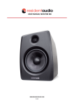
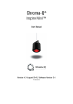
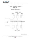
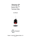
"
USER MANUAL MONITOR M5
WWW.RESIDENTAUDIO.COM
1 / 11
CONTENT
RESIDENT AUDIO M5
CONTENTS:
""
1. Instruction
2. The Product
2.1. Front Panel
2.2. Rear Panel
2.3. Rear Panel Chart
2.4. Description Rear Panel
3. Connection Process
3.1. Power Connection Process
3.2. Input Connection Process
4. Installation Process
4.1 Aligning Process
5. Technical Specifications
6. How To Clean The Product
7. Safety Instructions
8. Declaration of Conformity
03
04
04
04
05
06
07
07
07
08
08
09
10
10
11
RESIDENT AUDIO COPYRIGHT © 2014
WWW.RESIDENTAUDIO.COM
2 / 11
INSTRUCTIONS
RESIDENT AUDIO M5
"
"
"
"1. INSTRUCTION
"
The professional Resident Audio “Monitor M5“ near-field Studio Monitor speakers allow you to listen music
through a special Fiberglass Composite woofer material we specially made.
It features an extremely fat low-frequency response and an unprecedented punch in the lower mid-range.
Because of the excellent usage of the Fiberglass custom woofer technology we are able to break up
resonances, resulting in outstanding dynamic behavior and impeccable sound characteristics. The system
consists on a 3/4“ soft silk dome tweeter and 5 1⁄4" Fiberglass composite woofer.
The M-Series is designed to fully replicate the natural details of the source material. Multiple input
connections are integrated into the speaker and allow any system configuration.
"
"
"
"
"
"
"
"
"
"
"
"
"
"
"
"
""
""
""
""
""
""
RESIDENT AUDIO COPYRIGHT © 2014
WWW.RESIDENTAUDIO.COM
3 / 11
THE PRODUCT
RESIDENT AUDIO M5
"
""
"
"
2.1 THE FRONT SIDE
"
"
"
"
"
"
"
"
2.2 THE REAR SIDE
"
"
"
"
"
"
"
"
"
"
"
"
"
"
"
"
"
"
"
"
The front side of the MONITOR M5 contains the following:
• 3/4“ soft silk dome tweeter
• 5 1⁄4" Fiberglass composite woofer
• status LED (switches from Blue to Red between 22 and 30 minutes after stopped the usage)
The rear side of the MONITOR M5 contains the following:
• Input section
• Power section
• Specific Control section
• Caution section
• Specific product code
RESIDENT AUDIO COPYRIGHT © 2014
WWW.RESIDENTAUDIO.COM
4 / 11
THE PRODUCT
RESIDENT AUDIO M5
""
"
2.3 REAR PANEL CHART
"
"
"
"
"
"
"
4. VENT PORT
2. TRS INPUT
5. VOLUME KNOB
3. RCA INPUT
1. XLR INPUT
"
"
"
"
"
"
"
"
"
"
"
6. POWER SWITCH
"
"
"
"
"
"
"
"
"
"
"
"
"
"
"
"
"
"
7. POWER CORD RECEPTABLE
8. BAR CODE LABEL
RESIDENT AUDIO COPYRIGHT © 2014
WWW.RESIDENTAUDIO.COM
5 / 11
THE PRODUCT
RESIDENT AUDIO M5
""
""
"
2.4 DESCRIPTION REAR PANEL
"
1. XLR INPUT
Accepts balanced XLR input signals. The signal of the XLR input is mixed with the TRS input signal via a balanced input amplifier. The
XLR input is wired like this:
2. TRS INPUT
Accepts TRS input signals, either balanced or unbalanced. Use a 3-conductor TRS plug for balanced connections. The TRS input is wired
like this:
Unbalanced wiring works with either a 2- or 3-conductor TRS connector. With a 2-conductor TRS plug (a.k.a. TS plug) the minus signal
input is automatically grounded. With a 3-conductor TRS plug wired unbalanced the minus pin can be left open or grounded. We
recommend that you ground the unused input. The TRS input and the XLR input are summed together via a balanced input amplifier. So,
either may be used as an input or both may be mixed together. The input specifications apply to both inputs.
"
"
3. RCA Input
Accepts RCA input signals.
4. VENT PORT
The M8 is a vented box speaker system with a vent port on the rear panel. Don’ t block the vent port (e. g. by placing the speaker too
close to a wall) as this could change the overall sound.
"
5. VOLUME KNOB
Sets the proper input level from the sound source. The left and right speakers should be set up identically. Please refer to the illustration
on the right to chose the input level which best suits your sound source.
Further information can be found in the manual of the signal source connected to the speaker inputs. -10 dBV or +4 dBu are the most
common output levels of semi-professional and professional audio equipment. For example, if the output reference level of your sound
source is -10 dBV, you should not set the volume control knob higher than -10 dBV for maximum power.
"
"
"
6. POWER SWITCH
Push this switch to turn the M8 on/off.
7. POWER RECEPTABLE WITH EXTERNAL FUSE
Connect the detachable 3-circuit line cord to this receptacle and to a suitable power outlet.
8. BAR CODE LABEL
This label displays the product serial number bar code.
RESIDENT AUDIO COPYRIGHT © 2014
WWW.RESIDENTAUDIO.COM
6 / 11
CONNECTION PROCESS
RESIDENT AUDIO M5
"
"
"
"
"
3.1 POWER CONNECTION PROCESS
"
Set up your pair of MONITOR M5 speakers on a suitable surface.
Please make sure the power switch is turned off.
"
"
"
"
""
""
3.2 INPUT CONNECTION PROCESS
"
"
"
"
"
Please follow the following steps:
1. Choose the included power connector cable and plug into the power connector socket on the rear side of
the MONITOR M5
2. Take the other side of the power connector cable and plug it into an AC outlet
3. Turn the power switch on the back of the MONITOR M5 to the “ON” Position
MONITOR M5 will accept the following cable types;
Unbalanced RCA, Balanced 1/4" TRS or Balanced XLR.
Please follow the following steps:
1. Take your chosen audio connector cable and plug it into the specific audio
connector socket on the rear side of the MONITOR M5 input section
2. Make sure that your sound source has the volume turned down
3. Take the other side of the chosen audio connector cable from step 1 and plug it
into your sound source
"
"
"
"
"
RESIDENT AUDIO COPYRIGHT © 2014
WWW.RESIDENTAUDIO.COM
7 / 11
INSTALLATION PROCESS
RESIDENT AUDIO M5
"
"
"
"
"
4.1 ALIGNING PROCESS
To receive the best response of the MONITOR M5 speakers it is necessary to
align them correctly.
Please make sure that no other objects are in front of the speakers.
"
"
"
"
"
"
"
"
"
"
"
"
Please follow the following steps:
1. Align both speakers in the form of a triangle to the listener
2. Pay attention to use a reasonable ground for the speakers
3. The center of the speaker unit is recommended to be on the same height with the listener`s ears
"
"
"
"
"
"
"
"
"
"
RESIDENT AUDIO COPYRIGHT © 2014
WWW.RESIDENTAUDIO.COM
8 / 11
TECHNICAL SPECIFICATIONS
RESIDENT AUDIO M5
"
"
"
"
"
"
5. TECHNICAL SPECIFICATIONS
"
"
"
"
Configuration:
System type:
Low-Frequency:
High-Frequency:
Frequency Response:
Max Peak SPL:
Amplifier Class:
Power Output:
High Frequency:
Low Frequency:
Input Impedance (Ohms):
Indicators:
Input Connectors:
"
Enclosure Construction:
Finish:
Port Configuration:
Dimensions (D x W x H):
Weight:
2-Way
Active Studio Monitor
5¼" Fiberglass composite woofer
3/4" soft silk dome tweeter
45Hz -30kHz
104 dB
Class A-B
70W
30W
40W
10 K Ohm balanced
On(blue)/Standby(red)
- Unbalanced RCA
- Balanced 1/4" TRS
- Balanced XLR
MDF
Black vinyl wrap
Rear round port
7.8" (199mm) x 7.1" (181mm) x 9.9" (251mm)
3.6 Kg / 7.9 lbs
RESIDENT AUDIO COPYRIGHT © 2014
WWW.RESIDENTAUDIO.COM
9 / 11
SAFETY INSTRUCTIONS
RESIDENT AUDIO M5
"
"
""
6. HOW TO CLEAN THE PRODUCT
"
If you need to clean the unit, wipe it gently with a soft dry cloth. Do not use benzene, paint thinner, ethyl
alcohol or other chemical agents to clean the unit as they could damage the surface or cause fading.
""
"
7. SAFETY INSTRUCTIONS
"
1. Read the whole instruction manual
2. Keep these instructions
3. Heed all warnings
"
4. Follow all instructions
5. Do not use the product near water
6. Clean the product only with a soft dry cloth
7. Do not block any ventilation openings. Install in accordance with the manufacturer's instructions
8. Do not install near any heat sources such as radiators, heat registers, stoves, or other apparatus (including
amplifiers) that produce heat
9. Do not defeat the safety purpose of the polarized or grounding-type plug
10. Protect the power cord from being walked on or pinched particularly at plugs, convenience receptacles,
and the point where they exit from the apparatus
11. Only use attachments/accessories specified by the manufacturer
12. Unplug this apparatus during lightning storms or when unused for long periods of time
13. Refer all servicing to qualified service personnel. Servicing is required when the apparatus has been
damaged in any way, such as power-supply cord or plug is damaged, liquid has been spilled or objects have
fallen into the apparatus, the apparatus has been exposed to rain or moisture, does not operate normally, or
has been dropped.
"
"
RESIDENT AUDIO COPYRIGHT © 2014
WWW.RESIDENTAUDIO.COM
10 / 11
CONFORMITY
RESIDENT AUDIO M5
"
"
"
8. Declaration of Conformity (for the European Union)
"
The product described in this manual is manufactured in China by Resident Audio LLC. The product is
labelled with the CE mark and conforms to the protection requirements of the European Electromagnetic
Compatibility Standards and Directives. The product is designed and constructed such that electromagnetic
interferences generated do not exceed levels allowing radio and telecommunications equipment and other
equipment to operate as intended, and, the product has an adequate level of intrinsic immunity to
electromagnetic interferences to enable operation as specified and intended.
The product is marketed as M5 studio monitoring speaker.
With reference to regulations in the directives 73/23/EEC, 89/336/EEC, the equipment listed above is
covered by this certificate and labelled with the CE mark and conforms to the following standards:
EN60065 Safety requirements for mains operated electronic and related apparatus for household and similar
general use.
EN55103-1 & EN55103-2 Product family standard for audio, video, audio-visual and entertainment lighting
control apparatus for professional use.
"
RESIDENT AUDIO COPYRIGHT © 2014
WWW.RESIDENTAUDIO.COM
11 / 11