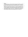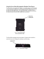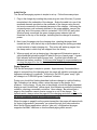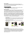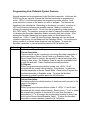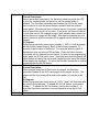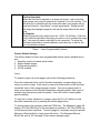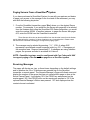
1
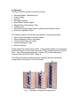
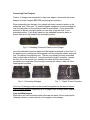
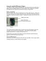
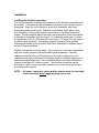
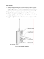
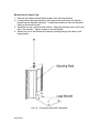
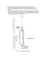
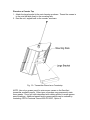
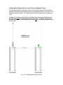
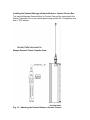
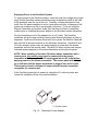
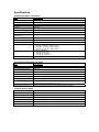
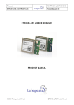
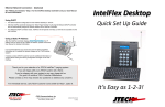
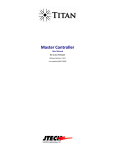
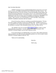
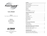
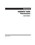
PREMISES PAGER SYSTEM®
ServAlert® 200 Series Server Paging System
Installation and Operation Guide
Part Number 321018 Rev G
April 2005
Introduction
JTECH Communications Inc., a subsidiary of
MICROS Systems Inc., designs and
manufactures cost effective in-house
communications systems for customers
throughout the world.
Thank you for choosing JTECH Communications Inc. as the provider for your onpremises paging needs. We truly appreciate your confidence in our products. At
JTECH, there is no greater commitment than providing you with total customer
satisfaction.
Please take a few minutes to review this guide prior to installing and operating your
system. The guide will provide you with installation instructions, give you answers to
the most frequently asked questions, and offer suggestions to ensure you receive all
of the many benefits your JTECH system can provide.
Additionally, this manual will assist you with problem determination and offer helpful
advice when seeking customer service. We are confident that JTECH
Communications offers the most responsive customer service available within the
industry.
Please do not hesitate to call JTECH Communications Customer Care at 800.3216221 or 561.997.0772, Option 6, if you have any questions. We look forward to a
long and mutually rewarding partnership.
- ii -
TABLE OF CONTENTS
INTRODUCTION ......................................................................................................................................1
TABLE OF CONTENTS...........................................................................................................................1
SYSTEM OVERVIEW AND COMPONENTS ..........................................................................................2
USING THE SERVERPASS RECHARGEABLE VIBRATION/TONE PAGERS ..................................12
USING THE INSTACALL™ NUMERIC PAGERS .................................................................................16
SERVALERT SYSTEM EXTENDED FUNCTIONS ...............................................................................17
SERVER CANCEL PANEL FUNCTION................................................................................................17
EXPEDITOR PANEL FUNCTION..........................................................................................................18
INSTALLATION .....................................................................................................................................19
INSTALLING THE SERVALERT TRANSMITTER ............................................................................................19
INSTALLING THE OPTIONAL SERVER CANCEL PANEL OR EXPEDITOR PANEL..............................................24
INSTALLING THE OPTIONAL MANAGER’S REMOTE BUTTON .......................................................................25
PROGRAMMING USER DEFINABLE SYSTEM FEATURES ..............................................................27
PAGING .................................................................................................................................................29
PAGING SERVERS FROM A GUESTALERT® SYSTEM ....................................................................30
RECEIVING MESSAGES ......................................................................................................................30
SYSTEM RANGE TEST AND DIAGNOSTICS .....................................................................................31
SPECIFICATIONS .................................................................................................................................32
SERVICE ................................................................................................................................................33
GENERAL TERMS AND CONDITIONS................................................................................................34
- iii -
System Overview and Components
System Overview
Congratulations on your purchase of the ServAlert® 200 Series Server Paging
System. The ServAlert transmitter provides a cost effective on-premises paging
solution for the hospitality industry and features the ability to immediately convey
to the wait staff when their order is ready in the kitchen.
The ServAlert transmitter can be ordered in 8,16 and 32-button models. All models can be
ordered with a Remote Panel. This manual covers all model types.
An optional Remote Panel can be ordered to enhance the operation of the
ServAlert system. When the optional panel is configured as a Server Cancel
Panel, it requires the waiter or waitress to cancel their page when picking up an
order. The Server Cancel Panel is programmed to automatically page a manager
if the page is not canceled within a specified time. When the optional remote
panel is configured as an Expeditor Panel, it allows a kitchen assistant or
expeditor to page wait staff at any time, making ServAlert an especially useful
tool during crucial peak times.
An optional Remote Manager’s Button, which connects to the ServAlert
transmitter, can also page a manager from a remote location such as a bar. An
optional Contact Closure accessory is also available to allow alerting when a
door, such as a managers office or rear door, is opened or closed. Using a
special “TEE” cable adapter, up to two of the three remote devices (remote
panel, remote button or contact closure) may be implemented with the ServAlert
transmitter.
The ServAlert 200 Series System is designed to support a paging area of up to a
mile or more. An optional Remote Antenna can be used to extend the
transmitting range. Paging distance will vary due to many factors, such as
building construction, as each location has its own distinct characteristics that
affect the coverage area. The ServerPass™ vibration pagers feature
rechargeable NiMH batteries to maximize ease of use and flexibility. Battery life
expectations are typically 1-3 years, but will vary depending on usage and
management of the pagers. ServerPass pagers should be returned to the
charger when not in use.
Components
The basic ServAlert system components include:
•
•
•
•
•
•
•
•
•
ServAlert Master Transmitting Unit
Power Adapter
Antenna
Mounting Hardware
ServerPass Vibration Pagers
Magnetic Server Assignment Tabs
Grease Pencil
ServAlert Premises Pager System Installation and Operator Guide
Warranty Registration Card
The following optional accessories are available to meet special needs:
•
•
•
•
•
Server Cancel/Expeditor Panel and cables
Remote Manager’s Button and cables
Contact Closure Box and cables
Numeric Manager’s Pager
Remote Antenna
Please inspect the system upon receipt. If the contents appear to be damaged,
contact the shipper to file a claim and notify JTECH Communications Customer
Care. If any components are missing, contact JTECH Communications
Customer Care at 800.321.6221, Option 6.
The following illustration depicts the three available ServAlert transmitter
configurations supporting 8, 16 and 32 pagers.
Fig. 1 – ServAlert Transmitter Configurations
Pagers
The ServAlert system supports ServerPass rechargeable vibration pagers and
the optional alkaline battery powered Numeric Manager’s Pager. The Numeric
Manager’s Pager displays the number of the server who has not canceled his
page after the designated period of time. The manager can be paged from the
ServAlert transmitter by pressing the PROG key. Pressing the PROG key from
the master transmitter will cause the Numeric Manager‘s Pager to display “99”.
Pressing the PROG key from the Server Cancel/Expeditor Panel will cause the
Numeric Manager‘s Pager to display “98”. Pressing the optional Manager
Remote Button will cause the Numeric Manager‘s Pager to display “00”.
Using the ServerPass Rechargeable Vibration/Tone Pagers
The ServerPass rechargeable UHF pager is a durable paging solution designed
to meet the rigorous requirements of the typical restaurant environment, as well
as other business applications. The ServerPass pager is configured with a
durable low profile belt clip designed especially for the restaurant environment.
An optional swivel belt clip is also available as an accessory.
Pager power
indicator light
and pager ID #
Fig. 2 – ServerPass Pager
with low profile belt clip
The ServerPass charging rack accommodates 10 pagers with low-profile or
swivel belt clip, and is designed for desktop or wall mounting.
Charger power
indicator light
Fig. 3 – ServerPass Charger
Initial Set Up
The ServerPass paging system is simple to set up. Follow these easy steps:
1. Plug in the charger by inserting the power plug into one of the two (2) power
receptacles in the underside of the charger. Snake the cable into one of the
recessed channels provided on the underside of the charger using the exit
slot most convenient to the desired placement of the charger. Assuming the
universal power cord is already attached to the power adapter, connect the
‘wall plug’ end of the power cord into a standard 110V/120V AC wall outlet.
When properly connected, the green charger power indicator light will
illuminate on the top of the charger, indicating that the charger is receiving
power.
2. Next, insert the pagers into the charging slots, orienting the pager label
toward the front, with the belt clip or promoback facing the opening provided
in the backside of each charging slot. This action will wake up pagers from
the sleep mode in which they are shipped from the factory.
3. When properly set into a charging bay, the pagers will illuminate a green or
yellow backlight behind the pager ID label on the top of each pager. A green
light indicates sufficient battery power level. A yellow light indicates an
extreme low battery condition. A 24-hour initial charge is recommended prior
to using the pagers for the first time to achieve published performance.
Pager Operation
The ServerPass pager is simple to operate. Approximately 5-seconds after a
pager is removed from the charging rack, the pager will exhibit a momentary alert
sequence indicating it’s readiness. At this time, the SOLID green “ready” light
will change to a FLASHING green “heartbeat” indicator.
During use, should this flashing heartbeat indicator change to a yellow flashing
light, indicating a low battery status, return the pager to the charger for a
minimum 1-hour charge. At any time in the charger, should the pager heartbeat
display a rapid “double flash” yellow signal, this indicates an extreme low battery
condition, requiring a mandatory minimum 1-hour charge. Be advised that a
pager in this condition cannot receive a page in or out of the charger. For
optimal results, always return the pagers to the charging rack when not in use for
the most convenient storage and maximum battery life.
When the pager is paged from the master transmitter, the pager will respond with
its’ factory programmed “personality” as ordered through your sales executive.
Most Server Paging applications use the “vibe only” configuration the pager
supports vibe/flash, vibe/tone or vibe/tone/flash paging alerts as well.
Receiving Pages
When a page is transmitted and received after charging the Pager for the
recommended time period, the ServerPass pager will alert depending on how it
has been ordered and subsequently programmed:
SERVER PROGRAMMING:
• Vibe/Tone pager: 2 seconds of VIBRATION, TONE or VIBE and TONE
cadence, depending on which product was ordered
Battery Installation
The rechargeable nickel metal hydride (NiMH) battery pack will typically last from
one to three years depending on usage. To replace the battery pack, first
remove the battery door screw from the rear of the pager using a small Phillips
head screwdriver. Slide the battery door down from the top to open. Place the
door and set screw in a safe place for closure after changing the rechargeable
battery pack. To facilitate battery replacement, in situations where the low-profile
belt-clip is in use (most ServerPass pagers), temporarily remove the belt clip too.
Next, carefully remove the old battery pack, disconnecting the plastic connector
from the port inside the pager. Plug in the replacement battery pack (JTECH part
number 232020.) To re-insert the replacement battery pack:
1) Feed the battery cable into the open area inside the pager housing to the
right of the port.
2) Place the battery into the available space by inserting the long side (with
the battery cable connector) into the space, rolling the other side of the
battery “down” into the housing.
3) Replace the battery door and re-secure it into place using the Phillips
head set screw.
Battery Door
Screw
Fig. 4 – Battery Installation
Clip Replacement
To replace a damaged ServerPass pager low-profile clip, or the rotary knob,
used with the two-piece cell-phone style swivel clip, follow the instructions above
to remove the battery door. With the door removed, remove the damaged clip or
the rotary knob. Replace with the appropriate replacement part available for
purchase as an accessory from JTECH Communications. Replace and resecure the battery door.
Connecting Two Chargers
Caution: If chargers are connected to the power adaptor, disconnect the power
adaptor from the chargers BEFORE performing this operation.
When connecting two chargers, first extend the stored connector plates on the
underside “rear” of the unit. (A small flat-tipped screwdriver is recommended for
use to initially slide out the connector tabs for accessibility.) Once accessible,
pull each of the two connector plates out until they “snap and lock” in the
extended position. Push firmly inward on the extended connector plates to
ensure they are in the locked in the extended position.
Fig. 5 – Extending Connector Plates on the Charger
Insert the extended connector plates into the female receptacles on the “front” of
the adjoining unit, pushing the units together until the connector plates “snap and
lock” into place in the adjoining unit. The two units should be firmly connected
flush to each other at this time. Using the included “pigtail” connector, connect
the first unit to the second unit, inserting the cable wire into the recesses
provided in the underside of the housing, ensuring the cable is under all of the
retaining tabs provided.
Fig. 6 – Connecting Chargers
Fig. 7 – “Pigtail” Power Connector
Up to two (2) charging units may be connected together on the same standard
JTECH power adapter, supporting up to 20 pagers from a single power adapter.
Care and Maintenance
Wipe with a soft cloth moistened with mild soap and water. Never spray liquids
(cleaning solution or water) directly on the pagers or the charger.
Using the InstaCall™ Numeric Pagers
The Numeric Pager integrates Managers into the communication loop with direct
paging as well as page escalation for servers when server response is hindered
or if pages are not canceled from the optional Sever Cancel Panel.
Battery Installation
Slide the battery door latch up toward the top of the pager (Fig. 8.) Follow the
direction of the arrow to remove the battery door. Insert one AAA alkaline battery
(supplied), observing the proper polarity. Replace the battery door and lock into
place.
Battery door latch
Insert AAA battery
observing proper polarity
Fig. 8
The InstaCall Numeric pager offers a back-lit top-mount LCD display panel and
message control buttons on the pager face. The InstaCall Numeric pager
displays date and time, as well as a low battery icon.
Please refer to the pocket User Manual enclosed with each InstaCall Numeric
pager for detailed operational instructions.
Care and Maintenance
Wipe with a soft cloth moistened with mild soap and water. Never spray liquids
(cleaning solution or water) directly on the pagers.
ServAlert System Extended Functions
Server Cancel Panel Function
The optional remote panel can be programmed to function as either a Server
Cancel Panel or an Expeditor Panel. The unit cannot serve both functions
simultaneously as the functions are mutually exclusive. The function of the
Server Cancel Panel is to cancel pages initiated on the ServAlert transmitter.
Once paged, servers must press the button associated with their name to
indicate they have picked up the order for which they were paged. Doing so
cancels their page. Failure to do so causes the system to continually page them
periodically until they “cancel” properly.
This periodic re-page function as noted above is based on a user definable “time
period”. Factory default for this time period is 40 seconds. (Please see the
Programming section of this guide for details on this feature.) Once any page is
initiated, the corresponding indicator on both the Master Transmitter and Server
Cancel Panel light steadily for the first “time period.” After the first specified time
period from the initial page without a “cancel,” the indicator light(s) will blink for a
second “time period.” If the optional Numeric Manger Pager is in use, a single
vibe and the corresponding server number is delivered to the Numeric Manager
Pager. This process repeats periodically thereafter until the appropriate cancel
button is pressed.
Once any page is issued, the corresponding indicator on both the Master
Transmitting and Server Cancel Panel light steadily for the first time period and
then blink until a page is canceled.
Expeditor Panel Function
The purpose of the Expeditor Panel is to allow both the chef and an “expeditor” to
page servers. The ServAlert transmitter and the Expeditor Panel page
independently so that pages may be issued from either the ServAlert transmitter
(chef’s area) or from the Expeditor Panel (expeditor’s area).
Once a page button is pressed on either unit, the indicator on both units will light
steadily for a time period and then blink for an additional time period before
turning off. The selected pager will receive a single one-second vibration (or
double or triple vibe, depending on user-configured default settings.) Double or
triple vibration pages may be also initiated individually if desired by pressing the
2X or 3X buttons first. (These 2X and 3X features are also available from the
ServAlert Master Transmitter.)
As noted above, the remote panel can be programmed to function as either a
Server Cancel Panel or an Expeditor Panel. The unit cannot serve both
functions simultaneously, as the functions are mutually exclusive.
Manager Remote Button or Contact Closure Box
An optional Manager Remote Button or Contact Closure Box may be connected to the
ServAlert transmitter for the purpose of paging the manager from a second location. If
the optional Numeric Manager Pager is used, the pager will display a “00” message when
this manager remote button is pressed or when the contact closure is activated. These
remote devices are attached to the ServAlert transmitter using a simple RJ-12 telephone
cable, and can be located up to 100 feet away in increments of 25 feet and are typically
configured at the time of purchase. The remote button is usually placed at a bar, hostess
area, front desk, office or wherever there is a need to call the manager. The contact
closure is normally found on a rear door or other normally secure area.
Optional Antenna
There are three types of optional antennas that can be used with the
ServAlert Master Transmitter. These remote antenna options may be used
to increase the paging coverage area. The remote antenna installations
should allow the antenna to be positioned as high as possible to maximize
range. The five-foot magnetic mount (mag mount) or six-foot hardware
mount antenna options replaces the standard wire antenna and are
connected to the ServAlert transmitter using a 25-foot cable. These
antenna options must be secured using the inclusive magnetic mount base
or with appropriate mounting hardware (not included) if the mounting
surface does not support magnetic attachment. The optional remote
antenna options can provide a 10%-20% gain in transmitter range,
depending on placement and building construction.
Installation
Installing the ServAlert transmitter
The first consideration regarding the placement of the ServAlert transmitter must
be usability. It should be readily accessible to all persons who will be using the
equipment. Since this unit contains its own built-in transmitter, pay close
attention to nearby obstructions. Stainless steel shelves, walls, pipes, ducts
mirrored glass or other similar barriers may weaken or misdirect transmitted
signals. Certain materials and construction, especially metal, have the potential
to partially or completely block the signal. For maximum performance, position
the placement of the tip of the antenna a minimum of 18” away from any metal to
minimize signal disruption. If necessary, optional extended range antenna
options are available for the ServAlert 200 Series transmitter to address many if
not all of these possibilities.
Another consideration involves safety. Be sure the unit is securely mounted and
safe from liquids, extreme heat and possible physical damage. Carefully
consider placement of any cords coming from the power adapters as not to
cause personal injury or damage to the system such as someone tripping on or
becoming tangled in the wires. Also, remember that the ServAlert transmitter
requires a standard A/C outlet for power. The ServAlert transmitter can be
mounted to a shelf, counter top, wall or placed on a counter using the inclusive
mounting bracket options.
NOTE:
All power, connection cables and the antenna must be connected
to the transmitter before applying power to the unit.
Shelf Mounted
1. Attach the large bracket securely to the main housing just above the center
using the supplied screws. The rubber bumpers should be toward the bottom
of the unit. Fasten the screws to the nuts that slide freely in the mounting
rails.
2. Loosely attach the small bracket to the main housing so that it can be
adjusted vertically in the mounting rails.
3. Hold the unit up to the shelf with the large bracket resting on the topside of
the shelf. Adjust the small bracket to come within 1/8” of the bottom side of
the shelf and tighten the screws to secure.
4. Install the clamp knob into the small bracket as shown and tighten on to the
shelf.
Fig. 9 – Shelf Mounted Transmitter
Mounted to a Counter Top
1. Remove the rubber channel and bumpers from the large bracket.
2. Loosely attach the large bracket to the main housing as shown so that the
bracket can be adjusted vertically. Thread the screws into the nuts that slide
freely in the mounting rails.
3. Stand the unit up on a horizontal surface. Adjust the bracket down until is sits
flat on the counter. Tighten screws to secure bracket.
4. Secure the unit to the horizontal surface by bolting through the holes in the
large bracket.
Fig. 10 – Countertop Mounted Transmitter
Wall Mount
1. Remove the rubber channel and bumpers from the large bracket.
2. Mount the large bracket to the wall. Anchor securely using four screws.
3. Mount the small bracket to the back of the ServAlert transmitter unit as
shown.
4. Mount the ServAlert transmitter unit to the wall by attaching the small bracket
to the large bracket with ¼” diameter by ½” long supplied screw and washer
as shown. The ServAlert transmitter unit can be swiveled on this single screw
to the desired position and then tightened.
Fig. 11 – Wall Mounted Transmitter
Placed on a Counter Top
1. Attach the large bracket to the main housing as shown. Thread the screws in
to the nuts that slide freely in the mounting rails.
2. Rest the unit, angled back on the counter, as shown.
Fig. 12 – Transmitter Placed on a Countertop
NOTE: Use only a grease pencil to enter server names on the ServAlert
transmitter magnetic panels. Other types of markers may permanently stain
these panels. Use a soft cloth dampened with rubbing alcohol to erase grease
pencil markings. Additional panels and/or grease pencils can be ordered by
contacting JTECH Customer Care at 800-321-6221, Option 6.
Installing the Optional Server Cancel Panel or Expeditor Panel
The ServAlert Master Transmitter Unit and the Remote Server Cancel Panel or
Expeditor Panel are interconnected and communicate through 6-conductor RJ-12
telephone data link cable. The cable snaps in at both ends just like a telephone
cord.
The Master Transmitter and the Cancel or Expeditor Panel must be linked together with
the RJ12 cable prior to connecting the power to the System. In addition, the Cancel or
Expeditor Panel must be connected to the AC outlet prior to connecting the Master Unit to
the AC outlet.
Fig. 13 – Attaching the Remote Panel
Installing the Optional Manager’s Remote Button or Contact Closure Box
The optional Manager Remote Button or Contact Closure Box connected to the
Master Transmitter Unit or the remote panel using another RJ-12 telephone cord
and a ‘TEE’ adapter.
Fig. 14 – Attaching the Remote Button or Contact Closure
Supplying Power to the ServAlert System
To supply power to the ServAlert system, insert the small low voltage plug (single
plug) into the ServAlert master transmitter power receptacle located on the side
of the assembly near the top of the unit. Carefully consider placement of any
cords from the power adapters as not to cause personal injury or damage to the
system as someone may trip or get tangled in the wires. If you are using the
Remote Panel with your system, make sure the Remote Panel is completely
installed prior to installing the power adapter to the ServAlert master transmitter.
Plug the transformer end of the adapter into an AC outlet. The ServAlert
transmitter will go through a self-test as the panel button lights begin to flash in
sequence. If you have a Remote Panel with your system, the Remote Panel will
also self-test in the same manner as the ServAlert transmitter. ServAlert 8 and
16 button systems require only one power adapter to power both the master
transmitter unit and the remote panel. ServAlert 32 button systems will require
individual power adapters for the master transmitter and the remote panel.
NOTE: When installing a ServAlert 32 button master transmitter with a
remote panel, the remote panel must be connected to the master
transmitter with the supplied RJ12 and plugged into an AC outlet before
applying power to the master transmitter. The remote panel will not light
up or self-test until the master transmitter is plugged into an AC outlet.
This sequence must be followed to ensure that the master transmitter
recognizes the remote panel.
If the ServAlert system fails to power up, check the AC outlet for power and
review this Installation Guide for proper installation.
To ServAlert Master
Fig. 15 – Transmitter Power Adapter
Programming User Definable System Features
Several features can be programmed in the ServAlert transmitter. Hold down the
PROG key for two seconds to place the ServAlert transmitter in programming
mode. LED’s 1-6 will illuminate when the programming mode is active. Next,
press the button number of the feature you wish to program. The features are
described in the table below. Depending on the feature you select, a number of
LED’s will illuminate indicating the possible choices. Make your selection by
pressing the appropriate button. To exit from the programming mode press the
ALL CALL button. For example, assume you want to change the default number
of vibrations the ServAlert transmitter Master is sending from two to three. After
placing the ServAlert transmitter in program mode you would press button
number two. LED’s 1-3 and 6-8 would illuminate indicating one, two and three
vibrations respectively for the Master and the Expeditor Panels. You would press
button number 3 to indicate three vibrations from the Master. To return the
ServAlert transmitter to normal operation press the All Call button once.
Button #
Button 1
Button 2
Program Feature
Server Cancel/Expeditor Mode
Feature Description:
A remote device can be connected to an existing ServAlert transmitter to
perform as either a Server Cancel Panel or an Expeditor Panel. The
Server Cancel Panel is used by the wait staff to cancel their pages after
picking up their order. The Expeditor Panel is used by an assistant chef
to page the wait staff. These functions are mutually exclusive.
To Program:
While in program mode press button number one. LED’s 1-2 will
illuminate with the current choice blinking. Press button 1 to place the
ServAlert transmitter in Server Cancel Mode. Press button 2 to place the
ServAlert transmitter in Expeditor mode. To return the ServAlert
transmitter to normal operation press the All Call button.
Number of Vibrations
Feature Description:
This feature selects the default number of vibrations sent from each of the
panels to the pagers.
To Program:
While in program mode press button number 2. LED’s 1-3 and 6-8 will
illuminate with the current choice blinking. Select button 1, 2 or 3 to select
the corresponding number of vibrations to be sent from the master
transmitter or 6, 7 or 8 to select the corresponding number of vibes to be
sent from the Server Cancel/Expeditor Panel. To return the ServAlert
transmitter to normal operation, press the All Call button.
Button 3
Button 4
Button 5
Pick Up Period
Feature Description:
Once a server has been paged, the ServAlert transmitter holds the LED
on solid for a selected time out period or until the cancel button is
pressed. The ServAlert transmitter then flashes the LED for the same
time out period or until the cancel button is pressed with the optional
cancel panel. If the second time out period expires, the server’s pager will
alert to remind him to pick up his order. If the server still does not cancel
for third time period, the manager’s pager (both vibration and numeric) as
well as the server’s pager will be paged. After each successive time out
period, the server and the manager will be paged until the cancel button is
pressed.
To Program:
While in program mode, press button number 3. LED’s 1-8 will illuminate
with the current choice blinking. Each of the buttons represents 10
seconds times the value of the button. For example, button number 5
represents a time out period of 50 seconds. Press the button number
associated with the desired time out period. To return to the programming
mode, press the All Call button once. (Note that twice this time period will
elapse before re-paging the server and 3 times this time period will elapse
before paging the manager.) To return the ServAlert transmitter to normal
operation press the All Call button.
All Call
Feature Description:
When enabled, when the All Call button is pressed, the ServAlert
transmitter flashes all the LED’s and pages all the pagers at once. The
pagers will vibe four times with a double vibe pattern to indicate an All
Call.
To Program:
While in program mode, press button 4. LED’s 1 and 2 will illuminate with
the current choice blinking. To enable the All Call feature, press button
number 1. To disable the All Call feature, press button number 2. To
return the ServAlert transmitter to normal operation press the All Call
button.
Reserved
Button 6
Range Test
Feature Described:
When the ServAlert transmitter is in range test mode, it will continually
send a page every nine (9) seconds for a period of four (4) minutes. This
will allow you to walk through the entire area where your pagers will be
used and check for “dead spots” or weak signal areas. Range test will
also page the manager’s pager so this can be range tested at the same
time.
To Program:
While in program mode, press button six. LED’s 1-8 will blink. Press the
button that corresponds to the pager you wish to use to conduct the range
test. You may only select one pager for the range test. To return the
ServAlert transmitter to normal operation, press any key or wait for the
four (4) minutes to elapse.
Table 1 – User-Programmable Features
Factory Default Settings
The factory defaults of these user-programmable feature options detailed above
are:
1. Expeditor mode (not cancel panel mode)
2. Single vibration pages
3. 40 second time period
4. All Call enabled
Paging
To initiate a page to a server pager, execute the following procedures:
Press the numbered button on the ServAlert transmitter corresponding to the
server you wish to page. Each server’s name should be written on the ServAlert
transmitter next to their assigned pager number. Use only a grease pencil to
enter server names on the ServAlert transmitter magnetic panels; other types of
markers may permanently stain the panels. Use a soft cloth to erase grease
pencil markings.
To send two or three vibrations to a pager, press the 2X or 3X buttons on the
ServAlert transmitter prior to pressing the desired page button.
To send a page to the manager, press the PROG key. The Manager’s pager will
display ‘99’ if the PROG key on the local panel is pressed or ‘98’ if the PROG key
on the remote panel is pressed. To send a page to a manager using the optional
Manager’s Remote Button, simply press the button. The Managers Remote
Button will send a “00” message to the numeric manager pager.
Paging Servers From a GuestAlert® System
If you have purchased a GuestAlert System for use with your patrons and desire
to page your servers or the manager to the front end of the restaurant, you may
alert with the following keystroke:
1. From the GuestAlert transmitter, press '90xx' where xx = the desired Server
number. For example, if you would like the Server with pager #8 to be alerted
from the Hostess desk using the GuestAlert 200 Series transmitter, you would
enter the number 9008#. In another instance, to pager the Server with pager
#12, enter the 9012# from the GuestAlert transmitter.
These Servers will receive an alert that differs from the alert that is sent from the kitchen,
and is characterized by a series of 16 short vibrations over a 4-second period. Please ensure
that servers are instructed accordingly to recognize this paging signal.
2. The manager may be alerted by pressing: *, 9, *, XXX, #, where XXX
represents a pre-defined numeric message code (e.g. 911 = “Emergency at
the reception area. Respond immediately.”) If managers are using vibration
pagers, the process and alert is as stated in #1 above.
NOTE: GuestAlert systems must be configured with Cap Code prefix ‘000’
to support paging of the ServerPass pagers on a ServAlert system.
Receiving Messages
The pager will vibrate one, two, or three times, depending on the default settings
and on whether the 2X or 3X buttons were pressed first on the ServAlert
transmitter or remote panel. The Numeric Manager’s Pager will vibrate once and
display the number of the server that has not canceled their page on time at the
Server Cancel Panel. It will display ‘99’ if the PROG key was pressed on the
master panel; ‘98’ if the PROG button on the remote was pressed or ‘00’ if the
optional Remote Manager’s Button was pressed. “00” also displays when the
contact closure is activated.
System Range Test and Diagnostics
Diagnostics
If the System does not page:
1. Check that the power adapter on the ServAlert transmitter is plugged in.
2. Verify that the Master Transmitter Unit has not been left in Program Mode
3. Verify the wall outlet is functioning.
4. Verify that the Pagers are on and have proper battery power (check indicator
light or remove and re-install battery.)
5. Verify appropriate placement of the transmitter unit such that the tip of the
antenna is at least 18” away from potential signal obstructions (e.g. metal.)
Range Test
The ServAlert transmitter can be put into a Range Test mode. When the unit is
in this mode, it will continually send a page every nine (9) seconds for a period of
four (4) minutes. This will allow you to walk through the entire area where your
pagers will be used and check for “dead spots” or weak signal areas. If you find
such areas, try relocating the ServAlert transmitter. If after relocating the
ServAlert transmitter there are still dead spots, you may need the optional
antenna.
To enter Range Test mode:
1. Press and Hold the Program button for two seconds. LED’s 1-8 will light up.
Press button numbered 6. LED’s 1-8 will blink.
2. Assuming you use pager number five, press button 5 on the ServAlert
transmitter. (Any vibrating pager may be utilized, but only one at a time.)
3. Secure the pager to your clothing as usual (do not hold the pager in your
hands) and move about the paging area checking for proper operation.
4. The selected pager will vibrate and the numeric manager’s pager will vibrate
and display during the range test.
Specifications
ServAlert 200 Series Transmitters
Item
Specification
Operating Voltage
12 volts
Operating Current
1.5 Amp maximum
Power Adapter
110/220 to 12 volt DC regulated transformer
Protocol
POCSAG
Operating Frequency
UHF Synthesized 467.750 – 467.950 MHz
Operating Temperature
-10 C to +55 C
Transmit Output Power
Transmitter Spurious
Better than -70 dBc
2 Watts nominal (+33dBm) into 50 ohm load
& Harmonics
Modulation
FSK Direct FM 512 BPS
Adjacent Channel Power
Better than -71dBc @ 12.5 kHz chnl. spacing
Frequency Stability
Better than 2.5 ppm
Varies by configuration
ServAlert 8: 198mm x 162mm x 58mm
ServAlert 16: 198mm x 162mm x 58mm
ServAlert 32: 322mm x 162mm x 58mm
Varies by configuration
ServAlert 8: 992 grams
ServAlert 16: 992 grams
ServAlert 32: 1406 grams
Dimensions
Weight
Antenna
Quarter wave
ServerPass Rechargeable UHF Pager
Item
Specification
Power Supply, Pager
1 Rechargeable – 2 x 2/3 AAA – 280mA NiMH Battery Pack, 2.4V
Transmit/Receive Protocol
POCSAG
Operating Frequencies
UHF synthesized 450 MHz-470 MHz. 12.5 KHz splinter channels
Pager Operating Temp. Range
0 C to +50 C
o
o
Size, Pager with Belt Clip
3.74" Tall (95.0 mm) x 2.12" Wide (53.8 mm) x 1.73" Deep (43.9 mm)
Weight, Pager with Belt Clip
0.20 lbs. (90.7 g)
Weight, Charger
1.6 lbs. (725 g) empty; 3.7 lbs. (1.67 kg) full
Exterior Dimensions, Charger
2.4" Tall (63.3 mm) x 13.5" Wide (342.9 mm) x 4.7" Deep (12.0 mm)
Power Supply, Charger (std.)
13.5V, 2.4A (supports 2 charger / 20 SERVERPASS pagers maximum)
(NOTE: Charger height with pager is 3.9” Tall)
InstaCall Numeric Pager
Item
Specification
Operating Voltage
Single ‘AAA’ Alkaline Battery 1.5 V
Protocol
POCSAG
Operating Frequency
UHF synthesized 450 MHz-470 MHz. 12.5 KHz splinter channels
Operating Temperature
0 C to +50 C-10 C to +55 C
Pager Size
2.46" Tall (62.6 mm) x 1.66" Wide (42.3 mm) x 1.24" Deep (31.4 mm)
Pager Weight
0.125 lbs. (56.6 g)
o
o
Service
If you need service, dial toll-free 800.321.6221 or 561.997.0772 and select
Option 6 for JTECH Customer Care. If your problem cannot be solved over the
phone by one of our service technicians, we will issue you a return materials
authorization (RMA) number for you to send the product in for service. Once
your product has been received by JTECH, it will be repaired and returned to you
with in the current posted lead-time. This is the standard Repair/Return program
and covers all pager products. (In lieu of a phone call, you may also send a fax to
561.997.5672 or e-mail us at “[email protected]”.)
As the most critical system component and integral to your business, the system
Master Transmitter is covered by our Advance Replacement program. When you
receive the replacement, simply place the defective transmitter unit in the same
box that it arrived in, attach the return address label to the outside of the box (this
label also includes your RMA number) and return it to us. All returned shipment
costs are the responsibility of the client. Advance Replacement services are also
offered on most pager products for your convenience. Ask your Customer Care
Representative about purchasing this value-added service.
When return-shipping products to JTECH, we recommend equipment be shipped
in a traceable manner for your protection. US Mail is not a recommended
method of shipment. Any equipment not received by JTECH Communications
within 20 days will be billed to the client at full retail value.
There are no charges for repaired equipment within the warranty period other
than your shipping costs. There may be an additional charge if, after the item is
returned and analyzed, it is determined to be “non-salvageable” - for example,
liquid damage, abused or misused. The standard warranty does not cover the
replacement of adapters, antennas, pager belt clips, pager promobacks, pager
battery doors, replaceable batteries, pager neck chains, liquid damage to master
transmitter and pagers, lightning strikes or other acts of God that could affect the
performance of the master transmitter, pagers and peripherals.
Check with Customer Care for extended warranty options, as well as the latest
charges for repair or replacement of equipment that is out of warranty. Any
order returned to JTECH is subject to a restocking fee. Refunds are on product
and tax only.
JTECH Communications is committed to providing reliable and responsive
service to our clients. We believe that our service is the most responsive,
comprehensive and cost-effective program in the industry.
General Terms and Conditions
This offer is subject to the terms and conditions listed below which are binding upon the seller and the buyer
under this offer and are hereby incorporated by reference in any subsequent agreement for purchase duly
executed between JTECH Communications Inc. (Seller) and its buyer of goods proposed for sale herein:
1. Price. All prices are F.O.B. point of origin, unless otherwise agreed to in writing by the buyer and seller. Prices quoted
are those in effect at the time of quotation and are valid for 30 days from the date of quotation regardless of existence of
any written confirmation. Until the proposal price and subsequent purchase price are paid in full, the buyer grants seller a
security interest in all of the goods described in this proposal all of the goods described in any resulting contract and buyer
agrees to sign on seller's request any required documentation to complete seller's said security interest.
2. Payment Terms. Normal payment terms are C.O.D. unless otherwise set forth in this proposal. Any outstanding
balances not paid by the date on which they are due to JTECH Communications Inc. shall be subject to interest of 1 1/2%
per month on the unpaid balance (or the maximum allowable by law whichever is the lessor) as well as rebilling charges
together with reasonable attorney's fees and paralegal fees including all such fees in any appeal together with all costs
associated with efforts by JTECH to enforce the terms of this proposal as well as all agreements between the parties. Any
discounts offered will be calculated from the date of invoice to the date that payment is received by JTECH or JTECH's
agents. Any discount is void if not taken at time of payment of the invoice containing said discount within thirty (30) days
of the date on which the goods for which the discount is allowed, have been received by Buyer, its agents or employees.
3. Products. Products are defined as those items listed on this proposal and a subsequent resultant purchase order to
JTECH containing items listed on this proposal.
4. Acceptance. Upon receipt the buyer shall immediately inspect and/or test the products. Unless stated otherwise in
writing on the final agreement between the parties, products shall be deemed accepted unless the buyer notifies JTECH
within 5 working days after receipt of shipment of any defect or discrepancy.
5. Transportation. Unless the buyer specifies the method of transportation, JTECH will use its best judgment in
determining the method of transportation. All costs of standard transportation, premium transportation if required through
no fault of JTECH, and other costs such as excise taxes, duty, freight forwarding or the like shall be billed to the buyer.
6. Title and Risk of Loss. Title of goods sold, shall pass to buyer at the F.O.B. point.
7. Limited Warranty for material and workmanship. JTECH (Seller) warrants to the buyer that products purchased
from JTECH shall be free from defects in material and workmanship under normal use and service. JTECH's obligation
under this warranty shall be limited to the repair or exchange of any part or parts which may thus prove defective under
normal use and service within one (1) year from date of purchase by the original purchaser, and which our examination
shall disclose to our satisfaction to be thus defective. THIS PROPOSAL AND SUBSEQUENT SALE ARE MADE ON THE
EXPRESS UNDERSTANDING THAT THERE IS NO IMPLIED WARRANTY THAT THE GOODS SHALL BE
MERCHANTABLE NOR AN IMPLIED WARRANTY THAT THE GOODS SHALL BE FIT FOR ANY PARTICULAR
PURPOSE. THE BUYER ACKNOWLEDGES THAT BUYER IS NOT RELYING ON THE SELLER'S SKILL OR
JUDGMENT TO SELECT OR FURNISH GOODS SUITABLE FOR ANY PARTICULAR PURPOSE AND THAT THERE
ARE NO WARRANTIES WHICH EXTEND BEYOND THOSE PREVIOUSLY SET FORTH HEREIN. PURCHASER IS
DIRECTED NOT TO RELY ON JTECH'S PRODUCTS TO FUNCTION AS AN INTEGRAL PART OF ITS LIFE
CARE/LIFE SUPPORT PROCEDURES OR SYSTEMS. JTECH'S PRODUCTS ARE NOT DESIGNED FOR SUCH USE;
PARTICULARLY WHEN AN ALLEGATION MAY BE MADE THAT PRODUCT MALFUNCTION CONTRIBUTED TO THE
FAILURE TO ADMINISTER A PROPER TREATMENT, PROCEDURE, ACTION OR MEDICATION. BUYER AGREES
TO FULLY PROTECT, DEFEND AND HOLD SELLER HARMLESS FROM CLAIMS OR DAMAGES RESULTING FROM
THE USE OF JTECH'S PRODUCTS IN LIFE CARE/LIFE SUPPORT PROCEDURES. Any claim by the buyer for the
repair or exchange of goods proposed and of goods actually sold to buyer shall be deemed waived by the buyer unless
submitted in writing to JTECH within the earlier of (a) 30 (thirty) days from the date the buyer discovered or by reasonable
inspection should have discovered any claimed breach of the foregoing warranty.
8. Damages Based Upon Negligence or Strict Liability. JTECH's obligation based upon any claim of negligence or of
strict liability as a result of its delivery of products ordered by Buyer, shall be limited to, at JTECH's option, repairing or
replacing the products that are found by JTECH to be defective, or refunding the purchase price of such products. In no
event shall JTECH's liability exceed the purchase price of the products which are subject matter of any such claim.
JTECH shall not be obligated to make any such refund or replacement until at least thirty (30) days after JTECH has
received from Buyer the subject alleged defective product, which will be shipped to JTECH at the buyer's expense.
9. Disclaimer of Consequential Damages. In no event shall JTECH be liable for incidental or consequential damages
arising out of or in connection with the purchase by Buyer of goods from JTECH including, without limitation, such
damages which may be caused by a breach of any obligation or warranty imposed on JTECH under such purchase.
Consequential damages shall include without limitation, loss of use, income or profit, or loss sustained as the result of
injury to any person, or loss or damage to any property, or loss or damages sustained as the result of work stoppage.
Buyer shall indemnify JTECH against all liability, cost or expense which may be sustained by JTECH due to loss, damage
or injury. IN NO EVENT, SHALL JTECH'S LIABILITY EXCEED THE PURCHASE PRICE OF GOODS.
10. Taxes. Unless specifically provided herein, the price for goods purchased as a result of this proposal does not include
sales, use, excise or similar taxes, whether Federal, State or local. Buyer is responsible for all applicable taxes for any
goods after title passes to the Buyer at the F.O.B. point. If Buyer is exempt from paying sales taxes, a certificate
evidencing such shall be provided to JTECH upon request.
11. Export. Buyer agrees not to directly or indirectly export any Goods purchased from JTECH (whether or not modified
by subsequent services) including, but not limited to parts, equipment, software or technical data/documentation without
first obtaining the required U.S. Government export license(s). If Buyer intends to export Goods outside the U.S., Buyer
shall determine whether an export license is required; and, if so, obtain that license from the U.S. Government. Buyer
shall protect, defend and indemnify JTECH from any loss or liability due to Buyer's failure to comply with export
regulations. Buyer furthers warrants that the Goods sold to Buyer from JTECH will not be resold, transferred, exported or
reused in any way by Buyer in violation of any laws, regulations or export control imposed by the U. S. Government.
12. Delays. Unless specified in writing by JTECH to the contrary, goods in stock shall be shipped immediately upon the
signing of a binding purchase agreement. Goods not in stock will be shipped as soon as possible. JTECH will not be
liable for any nonperformance of the Agreement resulting from this proposal caused by strikes, fires, disasters, riots, acts
of God or other causes or conditions beyond JTECH's reasonable control. In the event of such delay or nonperformance,
JTECH may, at its sole option, and without liability, cancel any portion of the Agreement resulting from this proposal
and/or extend any date upon which any performance is due.
13. Termination. If Buyer (a) fails to pay any amount owed when due, or (b) assigns or transfers the Agreement
subsequently resulting from this proposal without JTECH's prior written consent, or (c) makes an assignment for benefit of
creditors, or (d) files or has filed against it, petition for relief under federal or state bankruptcy laws, or (e) breaches any
other term or condition of this proposal or resultant contract, JTECH may terminate any portion of the agreement resulting
from this proposal in addition to JTECH's other available remedies. If JTECH fails to perform any obligation when due,
and if such failure is not remedied within thirty (30) days after receipt of written notice from Buyer, Buyer may terminate
any portion of such Agreement. In all other cases, the Agreement resulting from this proposal may be terminated by either
party by giving sixty (60) days written notice. Termination of the Agreement, for any reason, shall in no way interfere with
the obligation of Buyer to pay all monies payable as of the effective date of termination or which become payable for
Goods ordered and delivered after such termination. If such Agreement is terminated by Buyer for any reason other than
default by JTECH, Buyer shall be liable immediately thereupon, to pay to JTECH the full contract price for all goods
completed by JTECH pursuant to the Agreement and for all work in process at the time of termination.
14. Returns and Cancellations. Buyer may not cancel any order or return any Goods that have been special or custom
ordered, custom manufactured or configured, unless specifically agreed to in writing to seller in this proposal and in the
subsequent agreement. Returns are subject to a restocking fee which will be due to seller when the goods are received
by seller.
15. Patents and Copyrights. In no event shall JTECH be liable for damages arising from infringement of patents or
copyrights. In the event that Buyer should be enjoined in any such suit alleging infringement of patent(s) or copyright(s) or
proceeding from using any of the Goods purchased pursuant to this proposal and subsequent Agreement, JTECH, at its
option, shall either (a) secure termination of the injunction and procure for Buyer the right to use such goods without
obligation or liability or (b) replace or modify said Goods with non infringing materials at JTECH's expense and refund the
purchase price of the infringing goods to Buyer; provided, however, that in no event shall JTECH be liable for or have any
obligations under this paragraph if the alleged infringement is by reason of the specifications provided by Buyer to JTECH
under this agreement. The foregoing shall be Buyer's exclusive remedy against JTECH with respect to any alleged patent
or Copyright infringement. The sale of goods does not convey any license of copyright under any proprietary or patent
rights of any manufacturer. JTECH shall not have any liability if the alleged infringement is based upon the use or
application of the Goods in combination with other Goods and Buyer shall protect, defend, and indemnify JTECH
therefrom. JTECH disclaims all other liability for infringement of intellectual property rights and further disclaims any
liability for incidental or consequential damages arising in connection with such infringement.
16. Manufacturer Liability. In addition to JTECH's limited warranty for materials and workmanship as per section 7
herein, and unless specifically greed to in writing by the manufacturer, JTECH and Buyer, Buyer represents to JTECH and
the manufacturer that the Goods sold pursuant to this proposal and the subsequent resultant Agreement incorporating
such of the terms of this proposal agreed to by JTECH and buyer do not constitute standard components intended for use
by Buyer or JTECH in life support systems, surgical implantation, nuclear facilities, or for any other application in which
the failure of the Goods or the product in which the Goods are to be used could create a situation where personal injury or
death may occur.
17. Credit Terms. All orders and shipments shall at all times be subject to the approval of JTECH's credit department.
JTECH reserves the right of declining to make any shipment called for by the contract between seller and buyer
whenever, for any reason, there is doubt in JTECH's sole judgment, as to buyer's willingness or ability to pay for the goods
ordered on Buyer's solvency and JTECH shall not, in such event, be liable for breach or nonperformance of this
Agreement in whole or in part.
18. Packaging. Packaging will be standard commercial package and acceptable to commercial carriers. Special
customer packaging will be furnished only when specified and so stated herein and the cost thereof shall have been
agreed to by both the Buyer and JTECH in writing.
19. Substituted or Repaired Goods. If substitute additional or repaired goods are purchased by Buyer from JTECH, the
terms and conditions of this proposal and resultant Agreement shall be applicable thereto, the same as if such substituted,
additional or repaired Goods had been originally purchased hereunder unless specifically stated to the contrary in this
proposal or subsequent resultant Agreement.
20. General Conditions. No agent, salesman or other party is authorized to bind JTECH to any agreement, warranty,
statement, promise or understanding not expressed herein. The sale of Goods pursuant to this proposal and any
subsequent resultant Agreement shall be governed by the laws of the State of Florida. Any notice which is required under
the terms of a resultant Agreement shall be in writing and delivered to the address of the party set forth in the Agreement
and shall be effective when actually received. The remedies reserved by the parties shall be cumulative and in addition to
other remedies provided by law. JTECH shall not be required to proceed with the performance of any obligation under a
resultant Agreement so long as Buyer is in default or in breach of any of Buyer's obligations or agreements herein. Any
clerical errors are subject to correction. No delay or omission by JTECH in exercising any right or remedy under that
agreement shall constitute a waiver of such right or remedy. The waiver, invalidity or unenforceability of any provision in a
resultant Agreement shall not affect the validity of the agreement as a whole or any other provisions herein. An
Agreement resulting from this proposal shall be binding upon and shall inure to the benefit of the successors and assigns
of Buyer and JTECH. Buyer may not assign or transfer such Agreement in whole or in part without the prior written
consent of JTECH. For the purposes of such agreement, the Buyer and JTECH agree, notwithstanding any of the items
sold not constituting "goods" as defined in Article 2 of the Uniform Commercial Code as enacted and amended from time
to time in the state of Florida, for the purpose of interpreting this proposal or a resultant Agreement all items shall be
deemed to be such "goods." Buyer agrees that acceptance of this proposal and receipt of shipment from JTECH
pursuant to any resultant Agreement shall constitute acceptance in total of the preceding General Terms and
Conditions except as otherwise agree to in writing by the parties thereto.
© 2005 JTECH Communications, Inc.
Printed in USA
JTECH Communications Inc.
6413 Congress Ave., Suite 150
Boca Raton, Florida 33487 USA
Telephone: (800) 321-6221 Fax: (561) 997-0773
Voice: (561) 997-0772
Part Number: 321018G
Need Help? Got Questions? Call 800.321.6221 and ask for JTECH Customer Care