1
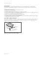
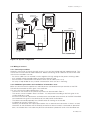
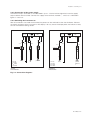
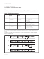
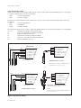
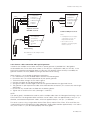
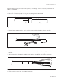
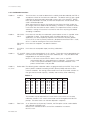
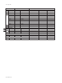
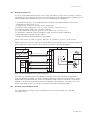
TABLE OF CONTENTS
PREFACE
1. INTRODUCTION AND GENERAL DESCRIPTION ..................................................................... 1-1
1-1. Instrument check ................................................................................................................... 1-1
1-2. Application ............................................................................................................................... 1-2
2. PH202 SPECIFICATIONS ............................................................................................................. 2-1
2-1. Genera• ................................................................................................................................... 2-1
2-2. Operating specifications ........................................................................................................... 2-2
2-3. Model and suffix codes ............................................................................................................ 2-3
2-4. Intrinsic safety - common specifications ................................................................................... 2-4
2-5. Connection diagrams for power supply.................................................................................... 2-5
3. INSTALLATION AND WIRING ...................................................................................................... 3-1
3-1. Installation and dimensions ...................................................................................................... 3-1
3-1-1. Installation site ............................................................................................................ 3-1
3-1-2. Mounting methods ...................................................................................................... 3-1
3-2. Preparation .............................................................................................................................. 3-3
3-2-1. Cables, terminals and glands ...................................................................................... 3-3
3-3. Wiring of sensors ..................................................................................................................... 3-4
3-3-1. General precautions .................................................................................................... 3-4
3-3-2. Additional precautions for installations in hazardous areas .......................................... 3-4
3-3-3. Hazardous area non-incendive PH 202S-N ................................................................ 3-4
3-3-4. Liquid earth ................................................................................................................. 3-5
3-3-5. Access to terminal and cable entry ............................................................................. 3-5
3-4. Wiring of power supply ............................................................................................................ 3-5
3-4-1. General precautions .................................................................................................... 3-5
3-4-2. Connection of the power supply ................................................................................. 3-5
3-4-3. Switching the instrument on........................................................................................ 3-6
3-5. Wiring the sensor system ......................................................................................................... 3-7
3-5-1. Impedance measurement jumper settings .................................................................. 3-7
3-6. Sensor wiring ........................................................................................................................... 3-8
3-6-1. Connection cable ........................................................................................................ 3-9
3-6-2. Sensor cable connection with special grommet ........................................................ 3-10
3-6-3. Sensor cable connections using junction box (BA10) and extension cable (WF10) ... 3-11
4. OPERATION; DISPLAY FUNCTIONS AND SETTING ................................................................. 4-1
4-1. Operator interface .................................................................................................................... 4-1
4-2. Explanation of operating keys .................................................................................................. 4-2
4-3. Setting passcodes ................................................................................................................... 4-3
4-3-1. Passcode protection ................................................................................................... 4-3
4-4. Display examples .................................................................................................................... 4-3
4-5. Display functions .................................................................................................................... 4-4
4-5-1. Display functions pH (default) ...................................................................................... 4-4
4-5-2. Display functions pH (ORP) ......................................................................................... 4-5
4-5-3. Display functions pH (rH)............................................................................................. 4-6
5. PARAMETER SETTING ................................................................................................................ 5-1
5-1. Maintenance mode .................................................................................................................. 5-1
5-1-1. Manual temperature selection and adjustment ............................................................ 5-2
5-1-2. Process temperature measuring in ORP mode ........................................................... 5-3
5-1-3. Manual activation of HOLD .............................................................................................. 5-4
5-1-4. Manual impedance check................................................................................................ 5-5
IM 12B6C3-E-E