1
K R A ME R E LE CT R O N IC S L T D .
USER MANUAL
MODEL:
VS-41HDCP
4x1DVI Switcher
P/N: 2900-000522 Rev 2
VS-41HDCP Quick Start Guide
This page guides you through a basic installation and first-time use of your VS-41HDCP.
For more detailed information, see the VS-41HDCP user manual. You can download the latest
manual at http://www.kramerelectronics.com.
Step 1: Check what’s in the box
1 Quick start sheet
The VS-41HDCP 4x1 DVI Switcher
1 User Manual
1 power adapter (5V DC)
4 rubber feet
RC-IR3 IR remote control transmitter with batteries and user manual
Save the original box and packaging materials in case your Kramer product needs to be returned to the
factory for service.
Step 2: Install the VS-41HDCP
Mount the machine in a rack (using the RK-1 rack adapter) or place on a table.
Step 3: Connect the inputs and output
Always switch off the power on each device before connecting it to your VS-41HDCP.
Computer
Graphics
Source (PC)
Display
PC Control
Device
For best results, we recommend that you always use Kramer high-performance cables to connect AV
equipment to the VS-41HDCP.
Step 4: Connect the power
Connect the 5V DC power adapter to the VS-41HDCP and plug the adapter into the mains
electricity.
Switch on the power to each device.
Step 5: Operate the VS-41HDCP
Acquire the EDID:
1. Connect the power supply.
2. Connect the new output display.
3. Press the EDID button.
4. Wait for the input buttons to stop blinking in sequence.
To acquire the default EDID, skip step 2 above.
Operate via the front panel buttons:
Operate the VS-41HDCP also via the RS-232, remote control contact closure and IR remote
control.
Contents
1
Introduction
1
2
2.1
Getting Started
Achieving the Best Performance
2
2
3
3.1
3.2
4
Overview
Defining EDID
About HDCP
Defining the VS-41HDCP 4x1 DVI Switcher
3
4
4
5
5
5.1
Connecting a VS-41HDCP 4x1 DVI Switcher
Connecting to the VS-41HDCP via RS-232
6
7
6
6.1
6.2
6.3
6.4
6.5
6.6
Operating the VS-41HDCP
The PC and DVD Modes
Setting the EDID
Controlling via the REMOTE Terminal Block Connector
Controlling the VS-41HDCP via the ETHERNET Port
Operating the VS-41HDCP using a Web Browser
Log On to the VS-41HDCP Web Pages
8
8
9
10
11
15
15
7
Firmware Upgrade
19
8
8.1
Technical Specifications
Default Communication Parameters
20
20
9
Default EDID
21
10
10.1
10.2
10.3
Kramer Protocol
Switching Protocols
Kramer Protocol 3000
Kramer Protocol 2000
22
22
23
32
Figures
Figure 1: VS-41HDCP 4x1 DVI Switcher Front Panel
Figure 2: VS-41HDCP 4x1 DVI Switcher Rear Panel
Figure 3: Connecting a VS-41HDCP 4x1 DVI Switcher
Figure 4: Connecting the Contact Closure Remote Control PINs
Figure 5: Local Area Connection Properties Window
Figure 6: Internet Protocol (TCP/IP) Properties Window
Figure 7: The Main Screen
Figure 8: Device Properties Screen
Figure 9: Java Test Page Success Message
Figure 10: The Loading Page
Figure 11: First Time Security Warning
Figure 12: VS-41HDCP Switching Matrix Page
Figure 13: Configurations Page
5
5
7
10
12
12
13
14
15
16
16
17
18
VS-41HDCP – Contents
i
U
U
U
U
U
U
U
U
1
Introduction
Welcome to Kramer Electronics! Since 1981, Kramer Electronics has been
providing a world of unique, creative, and affordable solutions to the vast range of
problems that confront the video, audio, presentation, and broadcasting
professional on a daily basis. In recent years, we have redesigned and upgraded
most of our line, making the best even better! Our 1,000-plus different models now
appear in 11 groups that are clearly defined by function.
Our 1,000-plus different models now appear in 11 groups that are clearly defined by
function: GROUP 1: Distribution Amplifiers; GROUP 2: Switchers and Matrix
Switchers; GROUP 3: Control Systems; GROUP 4: Format/Standards Converters;
GROUP 5: Range Extenders and Repeaters; GROUP 6: Specialty AV Products;
GROUP 7: Scan Converters and Scalers; GROUP 8: Cables and Connectors;
GROUP 9: Room Connectivity; GROUP 10: Accessories and Rack Adapters and
GROUP 11: Sierra Products.
Congratulations on purchasing your Kramer VS-41HDCP 4x1 DVI Switcher. The
VS-41HDCP is ideal for conference room presentations and advertising
applications, as well as for rental and staging.
VS-41HDCP - Introduction
1
2
Getting Started
We recommend that you:
Unpack the equipment carefully and save the original box and packaging
materials for possible future shipment
Review the contents of this user manual
Use Kramer high-performance high-resolution cables
Use only the power cord that is supplied with this machine
i
2.1
Go to http://www.kramerelectronics.com to check for up-to-date user
manuals, application programs (where appropriate), and to check if
firmware upgrades are available.
Achieving the Best Performance
To achieve the best performance:
Use only good quality connection cables to avoid interference, deterioration
in signal quality due to poor matching, and elevated noise levels (often
associated with low quality cables)
Avoid interference from neighboring electrical appliances that may adversely
influence signal quality
Position your Kramer VS-41HDCP away from moisture, excessive sunlight
and dust
!
2
Caution:
No operator serviceable parts inside the unit
Warning:
Use only the Kramer Electronics input power wall
adapter that is provided with the unit
Warning:
Disconnect the power and unplug the unit from the wall
before installing
VS-41HDCP - Getting Started
3
Overview
The VS-41HDCP is a high quality 4x1 switcher for DVI signals that supports up to
2.25Gbps bandwidth per graphic channel (suitable for resolutions up to UXGA at
60Hz, and for all HD resolutions). It equalizes the signal and switches one of the
four inputs to a single DVI output.
In particular, the VS-41HDCP:
Is HDCP (High Definition Digital Content Protection) compliant
Has four input selector buttons
Includes a MUTE button to disconnect the output and a PANEL LOCK button
to prevent unwanted tampering with the buttons on the front panel
Features a USB connector for setup and programming
Features EDID PassThru. Passes EDID/HDCP signals from source to
display
Features enhanced EDID (Extended Display Identification Data) - The unit
can store and recall an EDID setting in non-volatile memory from either the
default EDID or a connected output, allowing convenient and reliable
connection to the source
Is compact in size. Two units can be rack mounted side-by-side in a 1U rack
space with the optional Kramer RK-1 rack kit
Control the VS-41HDCP using the front panel buttons, or remotely via:
RS-232 serial commands (using Kramer 2000 and 3000 Protocols)
transmitted by a touch screen system, PC, or other serial controller
The Kramer infrared remote control transmitter
The ETHERNET
Remote control contact closure
VS-41HDCP - Overview
3
3.1
Defining EDID
The Extended Display Identification Data (EDID) is a data-structure provided by a
display, to describe its capabilities to a graphics card (that is connected to the
display’s source). The EDID enables the VS-41HDCP to “know” what kind of
monitor is connected to the output. The EDID includes the manufacturer’s name,
the product type, the timing data supported by the display, the display size,
luminance data and (for digital displays only) the pixel mapping data.
EDID is defined by a standard published by the Video Electronics Standards
Association (VESA).
3.2
About HDCP
The High-Bandwidth Digital Content Protection (HDCP) standard developed by Intel
protects digital video and audio signals transmitted over DVI or HDMI connections
between two HDCP-enabled devices to eliminate the reproduction of copyrighted
material. To protect copyright holders (such as movie studios) from having their
programs copied and shared, the HDCP standard provides for the secure and
encrypted transmission of digital signals.
4
VS-41HDCP - Overview
4
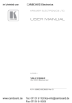
Defining the VS-41HDCP 4x1 DVI Switcher
Figure 1: VS-41HDCP 4x1 DVI Switcher Front Panel
#
1
Feature
IR Receiver
Function
The yellow LED lights when receiving signals from the Infrared
remote control transmitter
2
ON LED
Lights when receiving power
3
MUTE Button
Press to toggle disconnecting the output
4
INPUT SELECTOR Buttons
Press an INPUT button to select that input (from 1 to 4)
5
EDID Button
Press to acquire the EDID. This button illuminates when
configuring the EDID
6
PANEL LOCK Button
Press to toggle disengaging the front panel buttons
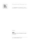
Figure 2: VS-41HDCP 4x1 DVI Switcher Rear Panel
#
1
Feature
INPUT DVI Connectors
Function
Connect to the DVI sources (from 1 to 4)
2
REMOTE Terminal Block
Connectors
Connect to a contact closure switch (see Section 6.1)
3
OUTPUT DVI Connector
Connect to the DVI acceptor
4
RS-232 9-pin D-sub Port
Connects to the PC or the RS-232 Remote Controller
5
SETUP/PROG USB Connector
Connect to a computer for firmware upgrade
6
PROG. Button
Push in for “Program” to upgrade to the latest Kramer
firmware (see Section 7), or release for Normal (the
factory default)
7
ETHERNET Connector
Connects to the PC or other Ethernet Controller
8
5V DC
+5V DC connector for powering the unit
VS-41HDCP - Defining the VS-41HDCP 4x1 DVI Switcher
5
5
Connecting a VS-41HDCP 4x1 DVI Switcher
i
Always switch off the power to each device before connecting it to your
VS-41HDCP. After connecting your VS-41HDCP, connect its power and
then switch on the power to each device.
To connect the VS-41HDCP 4x1 DVI Switcher (as illustrated in Figure 3), do the
following:
1.
Connect up to four computer graphics sources to the inputs (1 to 4).
You do not have to connect all the DVI sources.
2.
Connect the OUTPUT DVI connector to a DVI acceptor (for example, a
display).
3.
If required, connect a PC and/or controller to the RS-232 port and/or the
ETHERNET port (see Section 6.4).
4.
Connect the 5V DC power adapter to the power socket and connect the
adapter to the mains electricity (not shown in Figure 3).
5.
If required, acquire the EDID (see Section 6.1).
Press an INPUT SELECTOR button (from 1 to 4) to choose which DVI input to
route to the output.
6
VS-41HDCP - Connecting a VS-41HDCP 4x1 DVI Switcher
DVI
Computer
Graphics
Source 1
RS-232
DVI
DVI
Computer Graphics
Source 4
Display
Figure 3: Connecting a VS-41HDCP 4x1 DVI Switcher
5.1
Connecting to the VS-41HDCP via RS-232
You can connect to the VS-41HDCP via an RS-232 connection using, for example,
a PC. Note that a null-modem adapter/connection is not required.
To connect to the VS-41HDCP via RS-232:
Connect the RS-232 9-pin D-sub rear panel port on the VS-41HDCP unit via
a 9-wire straight cable (only pin 2 to pin 2, pin 3 to pin 3, and pin 5 to pin 5
need to be connected) to the RS-232 9-pin D-sub port on your PC
VS-41HDCP - Connecting a VS-41HDCP 4x1 DVI Switcher
7
6
Operating the VS-41HDCP
This section describes how to:
Operate the PC and DVD modes (see Section Section 6.1)
Acquire the EDID (see Section 6.2)
Control the machine via the REMOTE terminal block connector (see Section 6.3)
Control the machine via the ETHERNET port (see Section 6.4)
Control the machine via the Web pages (see Section 6.5)
6.1
The PC and DVD Modes
The VS-41HDCP has two operation modes that are specific per input: the PC mode
(which is the factory default) and the DVD mode. The PC mode is used when
connecting a computer or several computers to one or more of the inputs. The DVD
mode is used when connecting a DVD or several DVDs to the inputs.
The PC mode and the DVD mode can be applied to a single input or to several
inputs. For example, if you want to connect a computer to INPUT 1, another
computer to INPUT 2, and DVD machines to INPUT 3 and INPUT 4, set INPUT 1
and INPUT 2 to the PC mode and INPUT 3 and INPUT 4 to the DVD mode.
To set the inputs to either the PC or DVD mode, do the following:
1.
Turn off the POWER.
2.
Press the PANEL LOCK button while turning the POWER on again.
3.
Keep pressing and holding the PANEL LOCK button for a few seconds and
then release it.
The LOCK button blinks.
If an input button illuminates, this indicates that that input is set to the DVD
mode.
If an input button is not illuminated, this indicates that that input is set to the
PC mode.
8
VS-41HDCP - Operating the VS-41HDCP
4.
Toggle between the PC mode (input button not illuminated) and the DVD
mode (input button illuminated) by pressing that input.
5.
Press the PANEL LOCK button to exit this mode.
The following table summarizes the differences between the PC mode and the DVD
mode:
PC Mode
The input is connected to a computer
DVD Mode
The input is connected to a multimedia application,
such as a DVD, a set top box and so on
The EDID is available at all times (to prevent
computer reset)
The EDID is available only when that input is
connected to an output
The input EDID source is the default EDID or
an acquired EDID (see Section 6.1)
The input EDID source is acquired directly from
the connected output
Note, that even if an input is set to the PC mode, you can connect a DVD player to
that input and vice versa, a PC can be connected to an input that was set to the
DVD mode.
6.2
Setting the EDID
You can acquire or change the EDID (see Section 6.2.1) or reset the machine to the
default EDID (see Section 6.2.2).
If the connected output (for which EDID has already been acquired) is
disconnected, the EDID button blinks and then ceases blinking when reconnecting
the same output. When a new output is connected the EDID button blinks to
indicate that new EDID information must be acquired.
VS-41HDCP - Operating the VS-41HDCP
9
6.2.1
Acquiring / Changing the EDID
You can work with the default EDID or acquire or change an EDID via the
connected output. Use the EDID button to acquire the output EDID information.
To acquire or change the EDID of a new output display:
1.
Connect the power supply.
2.
Connect the new output display device.
The EDID button blinks.
3.
Press the EDID button.
The INPUT buttons blink in sequence until the EDID is acquired.
6.2.2
Resetting the Default EDID
To reset the default EDID, disconnect the output and repeat the steps in Section
6.2.1.
6.3
Controlling via the REMOTE Terminal Block Connector
The contact closure remote control pins operate in a similar way to the INPUT
SELECTOR button. Using the contact closure remote control you can select the
DVI input. To do so, momentarily connect the required input pin (IN 1, IN2, IN 3 or
IN 4) on the REMOTE terminal block connector to the GND (Ground) pin, as Figure
4 illustrates.
!
DO NOT connect more than one PIN to the GND PIN at the same time.
To select IN 1,
temporarily
connect the 1 PIN
to the G PIN
To select IN 2,
temporarily
connect the 2 PIN
to the G PIN
To select IN 3,
temporarily
connect the 3 PIN
to the G PIN
To select IN 4,
temporarily
connect the 4 PIN
to the G PIN
Figure 4: Connecting the Contact Closure Remote Control PINs
10
VS-41HDCP - Operating the VS-41HDCP
6.4
Controlling the VS-41HDCP via the ETHERNET Port
You can connect the VS-41HDCP via the Ethernet, using a crossover cable (see
Section 6.4.1) for direct connection to the PC or a straight through cable (see
Section 6.4.2) for connection via a network hub or network router.
6.4.1
Connecting the ETHERNET Port directly to a PC (Crossover
Cable)
You can connect the Ethernet port of the VS-41HDCP to the Ethernet port on your
PC, via a crossover cable with RJ-45 connectors.
i
This type of connection is recommended for identification of the factory
default IP address of the VS-41HDCP during the initial configuration.
After connecting the Ethernet port, configure your PC as follows:
1.
Right-click the My Network Places icon on your desktop.
2.
Select Properties.
3.
Right-click Local Area Connection Properties.
4.
Select Properties.
The Local Area Connection Properties window appears.
5.
Select the Internet Protocol (TCP/IP) and click the Properties Button (see
Figure 5).
VS-41HDCP - Operating the VS-41HDCP
11
Figure 5: Local Area Connection Properties Window
6.
Select Use the following IP Address, and fill in the details as shown in
Figure 6.
7.
Click OK.
Figure 6: Internet Protocol (TCP/IP) Properties Window
12
VS-41HDCP - Operating the VS-41HDCP
6.4.2
Connecting the ETHERNET Port via a Network Hub (StraightThrough Cable)
You can connect the Ethernet port of the VS-41HDCP to the Ethernet port on a
network hub or network router, via a straight-through cable with RJ-45 connectors.
6.4.3
Configuring the Ethernet Port
To configure the Ethernet port, download the K-UPLOAD Ethernet configuration
software. Extract the file to a folder and create a shortcut on your desktop to the file.
Follow these steps to configure the port:
1.
Double click the K-UPLOAD desktop icon.
The main screen appears:
Figure 7: The Main Screen
VS-41HDCP - Operating the VS-41HDCP
13
2.
Click the Connect button to connect to the machine to select the method to
connect to the Ethernet port of the VS-41HDCP.
Select:
Ethernet, if you know the IP address number or the machine name.
The default name for the machine is KRAMER_XXXX (the four digits
are the last four digits of the machine’s serial number)
Serial, if you are connected via a serial port
USB, if you are connected via the USB
3.
Select the connection method and click Connect .
Figure 8: Device Properties Screen
4.
14
If required, make changes and click Save. If not, click Exit.
VS-41HDCP - Operating the VS-41HDCP
6.5
Operating the VS-41HDCP using a Web Browser
The embedded Web pages can be used to remotely operate the VS-41HDCP using
a Web browser and an Ethernet connection.
Before attempting to connect:
Perform the procedures in Section 6.4.
Ensure that the Java™ software is installed and functioning correctly on your
computer. If not, download it from www.java.com
Ensure that your browser is supported—Microsoft IE (V6.0 and higher),
Google Chrome, Firefox (V3.0 and higher).
To check that Java is installed and running correctly, browse to
http://www.java.com/en/download/help/testvm.xml
This page runs a test and displays a Java success (see Figure 9) or failure
message.
Figure 9: Java Test Page Success Message
If you do not see the success message, follow the instructions on the page to:
Load and enable Java
Enable Javascript in your browser
6.6
Log On to the VS-41HDCP Web Pages
To log on to VS-41HDCP Web pages:
1.
Open your Internet browser.
2.
Type the unit’s IP number in the Address bar of your browser.
VS-41HDCP - Operating the VS-41HDCP
15
The Loading page appears.
Figure 10: The Loading Page
The first time that you run the program, the Warning-Security screen appears:
Figure 11: First Time Security Warning
3.
Click Run.
The main switching control Home page is displayed which shows a graphical
interpretation of the front panel (see Figure 12).
16
VS-41HDCP - Operating the VS-41HDCP
The Web pages let you control the VS-41HDCP via the Ethernet. The menu
appears on the left side of the screen. There are two remote operation Web pages:
The PANEL main page (see Section 6.6.1)
The configurations page (see Section 6.6.2)
A description of each Web page is displayed if you hover your mouse over the
question mark
6.6.1
that appears on the left side of the screen.
The PANEL Main Page
The VS-41HDCP main page inputs to the output by clicking the audio and/or video
signal indicators (purple and blue, respectively).
Figure 12: VS-41HDCP Switching Matrix Page
You can perform the following operations via this Web page:
Select an input to switch to the output by clicking an input selector button
Acquire the EDID (see Section 6.1)
Click the Lock button to lock or unlock the front panel
Click the Mute button to mute the audio signal
VS-41HDCP - Operating the VS-41HDCP
17
6.6.2
The CONFIGURATIONS Page
The Configurations page lets you view some Ethernet settings and change others
(see Figure 13). Fields with a white background are editable; fields with a blue
background are read-only.
To change the configuration definitions:
1.
Click CONFIGURATIONS.
The Configurations Web page appears.
2.
Modify the values as required.
3.
Click the blue Submit button to apply changes or Cancel to abandon them.
A confirmation window appears asking if you are sure you want to change the
network settings.
4.
Click Yes.
A window appears informing you that the configuration has been successfully
changed.
5.
Click OK.
6.
If the IP address has been changed, close your browser and reload the Web
page using the new IP address.
Figure 13: Configurations Page
18
VS-41HDCP - Operating the VS-41HDCP
7
Firmware Upgrade
For instructions on upgrading the firmware, see the K-UPLOAD guide.
The latest version of firmware and installation instructions can be downloaded from
the Kramer Web site at www.kramerelectronics.com.
VS-41HDCP - Firmware Upgrade
19
8
Technical Specifications
INPUTS:
4 DVI Connectors
OUTPUT:
1 DVI Connector
BANDWIDTH:
Supports up to 2.25Gbps bandwidth per graphic channel
COMPLIANCE WITH HDMI
STANDARD:
Supports HDMI and HDCP
RESOLUTION:
Up to 1080p, UXGA
POWER SOURCE:
5V DC, 360mA
CONTROLS:
Front panel buttons, Infrared remote control transmitter, RS-232,
contact closure remote control, Ethernet
DIMENSIONS:
WEIGHT:
22cm x 18cm x 4.5cm (8.6” x 7” x 1.8”) W, D, H
1.3kg (2.9lbs) approx.
ACCESSORIES:
Power supply
OPTIONS:
Kramer DVI cables, RK-1 rack adapter
Specifications are subject to change without notice
Go to our Web site at http://www.kramerelectronics.com to access the list of resolutions
8.1
Default Communication Parameters
EDID
Passes EDID/HDCP signals between the display and the source
RS-232
Protocol 2000
Protocol 3000 (Default)
Baud Rate:
9600
Baud Rate:
Data Bits:
8
Data Bits:
115,200
8
Stop Bits:
1
Stop Bits:
1
Parity:
None
Parity:
None
Command Format:
HEX
Command Format:
ASCII
Example (Output 1 to Input 1):
0x01, 0x81, 0x81, 0x81
Example (Output 1 to Input 1):
#AV 1>1<CR>
Switching Protocol
P2000 -> P3000
P3000 -> P2000
Command:
Command:
#P2000<CR>
Front Panel:
Press and hold input 1 and input
2 simultaneously
0x38, 0x80, 0x83, 0x81
Front Panel: Press and hold input 1 and input 3
simultaneously
Ethernet
Default Settings
Reset Settings
IP Address: 192.168.1.39
Power cycle the unit while holding in the Factory
Reset button, located on the rear panel of the
unit.
TCP Port #: 5000
UDP Port #: 50000
20
VS-41HDCP - Technical Specifications
9
Default EDID
The factory default EDID is listed below.
Monitor
Model name............... VS-41HDCP
Manufacturer............. KRM
Plug and Play ID......... KRM7300
Serial number............ 505-707455010
Manufacture date......... 2009, ISO week 10
------------------------EDID revision............ 1.3
Input signal type........ Digital
Color bit depth.......... Undefined
Display type............. RGB color
Screen size.............. 520 x 320 mm (24.0 in)
Power management......... Standby, Suspend, Active off/sleep
Extension blocs.......... 1 (CEA-EXT)
------------------------DDC/CI................... Not supported
Color characteristics
Default color space...... Non-sRGB
Display gamma............ 2.20
Red chromaticity......... Rx 0.674 - Ry 0.319
Green chromaticity....... Gx 0.188 - Gy 0.706
Blue chromaticity........ Bx 0.148 - By 0.064
White point (default).... Wx 0.313 - Wy 0.329
Additional descriptors... None
Timing characteristics
Horizontal scan range.... 30-83kHz
Vertical scan range...... 56-76Hz
Video bandwidth.......... 170MHz
CVT standard............. Not supported
GTF standard............. Not supported
Additional descriptors... None
Preferred timing......... Yes
Native/preferred timing.. 1280x720p at 60Hz (16:10)
Modeline............... "1280x720" 74.250 1280 1390 1430 1650 720 725 730 750 +hsync +vsync
Standard timings supported
720 x 400p at 70Hz - IBM VGA
640 x 480p at 60Hz - IBM VGA
640 x 480p at 75Hz - VESA
800 x 600p at 60Hz - VESA
800 x 600p at 75Hz - VESA
1024 x 768p at 60Hz - VESA
1024 x 768p at 75Hz - VESA
1280 x 1024p at 75Hz - VESA
1280 x 1024p at 60Hz - VESA STD
1600 x 1200p at 60Hz - VESA STD
1152 x 864p at 75Hz - VESA STD
VS-41HDCP - Default EDID
21
10
Kramer Protocol
You can download our user-friendly Software for Calculating Hex Codes for
Protocol 2000” from the technical support section on our Web site at
http://www.kramerelectronics.com.
Section 10.1 describes how to switch between Protocol 3000 and Protocol 2000.
Section 10.2 defines Protocol 3000 and Section 10.3 defines Protocol 2000.
By default, the VS-41HDCP is set to Kramer’s Protocol 3000, but it is also
compatible with Protocol 2000.
10.1
Switching Protocols
You can switch protocols either via the front panel buttons (see Section 10.1.1) or
by sending protocol commands (see Section 10.1.2).
10.1.1
Switching Protocols via the Front Panel Buttons
To switch from Protocol 3000 to Protocol 2000, press and hold the INPUT 1 and
INPUT 2 buttons for a few seconds (not as part of the switching operation).
To switch from Protocol 2000 to Protocol 3000, press and hold the INPUT 1 and
INPUT 3 buttons for a few seconds.
i
10.1.2
The Windows®-based Kramer control software operates with Protocol 2000.
If the VS-41HDCP is set to Protocol 3000, use the front panel buttons to
switch to Protocol 2000
Switching Protocols via Protocol Commands
To switch from Protocol 3000 to Protocol 2000, send the following command:
#P2000<CR>
To switch from Protocol 2000 to Protocol 3000, send the following command:
0x38, 0x80, 0x83, 0x81
22
VS-41HDCP - Kramer Protocol
10.2
Kramer Protocol 3000
This RS-232/RS-485 communication protocol lets you control the machine from any
standard terminal software (for example, Windows® HyperTerminal) with default
settings of 115200 baud data rate, no parity, 8 data bits, and 1 stop bit.
10.2.1
Protocol 3000 Syntax
Host message format:
Start
#
Address (optional)
Destination_id@
Body
message
Delimiter
CR
Simple command (commands string with only one command without addressing):
start
#
body
Command SP Parameter_1,Parameter_2,…
delimiter
CR
Commands string (formal syntax with commands concatenation and addressing):
# Address@ Command_1 Parameter1_1,Parameter1_2,… |Command_2
Parameter2_1,Parameter2_2,… |Command_3 Parameter3_1,Parameter3_2,…
|…CR
Device message format:
Start
~
Address (optional)
Sender_id@
Body
message
Delimiter
CR LF
Device long response (Echoing command):
Start
~
Address (optional)
Sender_id@
Body
command SP [param1 ,param2 …] result
Delimiter
CR LF
CR = Carriage return (ASCII 13 = 0x0D)
LF = Line feed (ASCII 10 = 0x0A)
SP = Space (ASCII 32 = 0x20)
VS-41HDCP - Kramer Protocol
23
10.2.2
Command Parts Details
Command:
Sequence of ASCII letters ('A'-'Z', 'a'-'z' and '-').
Command will separate from parameters with at least single space.
Parameters:
Sequence of Alfa-Numeric ASCII chars ('0'-'9','A'-'Z','a'-'z' and some special chars for specific commands), parameters
will be separated by commas.
Message string:
Every command must to be entered as part of message string that begin with message starting char and end with
message closing char, note that string can contain more then one command separated by pipe ("|") char.
Message starting char:
'#' for host command\query.
'~' for machine response.
Device address (Optional, for Knet):
Knet Device ID follow by '@' char.
Query sign = '?', will follow after some commands to define query request.
Message closing char =
Host messages - Carriage Return (ASCII 13), will be referred to by CR in this document.
Machine messages - Carriage Return (ASCII 13) + Line-Feed (ASCII 10), will be referred to by CRLF.
Spaces between parameters or command parts will be ignored.
Commands chain separator char:
When message string contains more than one command, commands will be separated by pipe ("|").
Commands entering:
If terminal software used to connect over serial \ ethernet \ USB port, that possible to directly enter all commands
characters (CR will be entered by Enter key, that key send also LF, but this char will be ignored by commands parser).
Sending commands from some controllers (like Crestron) require coding some characters in special form (like \X##).
Anyway, there is a way to enter all ASCII characters, so it is possible to send all commands also from controller.
(Similar way can use for URL \ Telnet support that maybe will be added in future).
Commands forms:
Some commands have short name syntax beside the full name to allow faster typing, response is always in long syntax.
Commands chaining:
It is possible to enter multiple commands in same string by '|' char (pipe).
In this case the message starting char and the message closing char will be entered just one time, in the string
beginning and at the end.
All the commands in string will not execute until the closing char will be entered.
Separate response will be sent for every command in the chain.
Input string max length:
64 characters.
Backward support:
Design note: Transparent support for Protocol 2000 will be implemented by switch Protocol command from Protocol
3000 to Protocol 2000, in Protocol 2000 there is already such a command to switch Protocol to ASCII Protocol (#56 :
H38 H80 H83 H81).
Command Name
#
Instruction Codes for Protocol 3000
Short Cmd
Command Type
Common-mandatory
Permission
End User
Protocol handshaking
Syntax
#
Response
~nn@
OK
Parameters
Notes
Use to validate protocol 3000 connection and to get machine number.
24
VS-41HDCP - Kramer Protocol
Command Name
BUILD-DATE
Short Cmd
Command Type
Common-mandatory
Permission
End User
Read device build date
Syntax
#BUILD-DATE?
Response
~nn@BUILD-DATE
date
time
Parameters
date – Format: YYYY/MM/DD where YYYY = Year. MM = Month. DD = Day.
time – Format: hh:mm:ss where hh = hours. mm = minutes. ss = seconds.
Command Name
MODEL?
Short Cmd
Command Type
Common-mandatory
Permission
End User
Read device model
Syntax
#MODEL?
Response
~nn@MODEL
model_name
Parameters
model_name – String of printable ASCII chars (up to 19 chars).
Command Name Short Cmd
SN?
Reset device serial number
Command Type
Common-mandatory
Permission
End User
Syntax
#SN?
Response
~nn@SN
serial_number
Parameters
serial_number – 11 decimal digits. Assign by Kramer factory.
Notes
For new products with 14 digits serial we kept only the last 11.
Command Name
VERSION?
Short Cmd
Command Type
Common-mandatory
Permission
End User
Reset device serial number
Syntax
#VERSION?
Response
~nn@VERSION
firmware_version
Parameters
firmware_version – Format: XX.XX.XX.XXXX where the digit groups are:
Major.Minor.Build.Revision
VS-41HDCP - Kramer Protocol
25
Command Name
LOCK-FP
Short Cmd
Command Type
Common
Permission
End User
Lock front panel
Syntax
Option 1: #LOCK-FP
lock_mode
Option 2: #LOCK-FP
device_id, lock_mode
Response
Option 1: ~nn@LOCK-FP
lock_mode
Option 2: ~01@LOCK-FP
device_id,lock_mode
OK
OK
Parameters
lock_mode – ‘0’ or ‘off’ to unlock front panel buttons. ‘1’ or ‘on’ to lock front panel buttons.
device_id – For K-Net controllers, select the buttons panel to lock. Locking is allowed only
from the master.
Command Name
LOCK-FP?
Short Cmd
Command Type
Common
Permission
End User
Get lock state of front panel
Syntax
Option 1: #LOCK-FP?
Option 2: #LOCK-FP?
device_id
Response
Option 1: ~nn@LOCK-FP
lock_mode
Option 2: ~01@LOCK-FP
device_id, lock_mode
Parameters
lock_mode – ‘OFF’ for unlocked front panel. ‘ON’ for locked front panel.
device_id – For K-Net controllers, select the buttons panel to get lock state. State is
available only from the master.
Command Name
NAME?
Short Cmd
Command Type
Common (Ethernet)
Permission
End User
Get machine (DNS) name
Syntax
#NAME?
Response
~nn@NAME
machine_name
Parameters
machine_name – String of up to 14 alpha-numeric chars (can include hyphen, not in
beginning or end).
Notes
The machine name is not the same as the model name. The machine name is used to
identify a specific machine or a network in use (with DNS feature on).
26
VS-41HDCP - Kramer Protocol
Command Name
AV
Short Cmd
Command Type
Switch
Permission
End User
Switch Audio and Video
Syntax
#AV
in>out, in>out,…
Response
~nn@AV
in>out, in>out,…
Parameters
In - input number or '0' to disconnect output
'>' = Connection character between in and out parameters
out = Output number or '*' for all outputs
Command Name
VID
Short Cmd
V
Command Type
Switch
Permission
End User
Switch Video
Syntax
#VID
in>out, in>out,…
Response
~nn@VID
in>out
~nn@VID
in>out
…
Parameters
In - input number or '0' to disconnect output
'>' = Connection character between in and out parameters
out = Output number or '*' for all outputs
Notes
When AFV switching mode is active, this command also switches Audio and the unit replies
with command ~AV.
Command Name
VID?
Short Cmd
V?
Command Type
Switch
Permission
End User
Get Video Switch Stat
Syntax
#VID?
out
#VID?
*
Response
~nn@VID
in>out
~nn@VID
in>1 , in>2 , …
Parameters
in - input number or '0' to disconnect output
'>' = Connection character between in and out parameters
out = Output number or '*' for all outputs
VS-41HDCP - Kramer Protocol
27
Command Name Short Cmd
ETHP
ETH-PORT
Command Type
Ethernet
Permission
Administrator
Change protocol Ethernet port
Syntax
#ETH-PORT
protocol, port
Response
~ nn@ETH-PORT
protocol, port
OK
Parameters
protocol = TCP or UDP (transport layer protocol)
port = Ethernet port that accepts Protocol 3000 commands:
1-65535 = User defined port
0 - Reset port to factory default (50000 for UDP, 5000 for TCP)
Notes
Device may get new setting only after restart or closing current port.
Some device port 50000 is the default also for TCP
Resetting port by value 0 may not work in all devices
For proper settings consult your network administrator
Command Name
ETH-PORT?
Short Cmd
ETHP?
Command Type
Ethernet
Permission
End User
Get protocol Ethernet port
Syntax
#ETH-PORT?
protocol
Response
~ nn@ETH-PORT
protocol, port
Parameters
protocol = TCP or UDP (transport layer protocol)
port = Ethernet port that accepts Protocol 3000 commands.
Notes
Default Port is 50000 for UDP, 5000 for TCP
Some device has port 50000 as default also for TCP
Command Name Short Cmd
NTDH
NET-DHCP
Command Type
Ethernet
Permission
Administrator
Set DHCP mode
Syntax
#NET-DHCP
mode
Response
~ nn@ NET-DHCP
mode
OK
Parameters
mode - ‘0’ – Don't use DHCP (Use IP set by factory or IP set command).
‘1’ – Try to use DHCP. If unavailable, use IP as above.
Notes
Connection of Ethernet to devices with DHCP may take more time in some networks.
To allow connecting if randomly assigned IP by DHCP - Give the device DNS name (if
available) by the command “NAME”. It possible to get assigned IP also by direct connection
to USB or RS-232 protocol port if available.
For proper settings consult your network administrator
28
VS-41HDCP - Kramer Protocol
Command Name
NET-DHCP?
Short Cmd
Command Type
Ethernet
NTDH?
Permission
End User
Get DHCP mode
Syntax
#NET-DHCP?
Response
~ nn@ NET-DHCP
mode
Parameters
mode - ‘0’ – Don't use DHCP (Use IP set by factory or IP set command).
‘1’ – Try to use DHCP. If unavailable, use IP as above.
Notes
Connection of Ethernet to devices with DHCP may take more time in some networks.
To allow connecting if randomly assigned IP by DHCP - Give the device DNS name (if
available) by the command “NAME”. It possible to get assigned IP also by direct connection
to USB or RS-232 protocol port if available.
Command Name
NET-GATE
Short Cmd
Command Type
Ethernet
NTGT
Permission
Administrator
Set Gateway IP
Syntax
#NET-GATE
ip_address
Response
~ nn@ NET-GATE
ip_address
OK
Parameters
ip_address – format: xxx.xxx.xxx.xxx
Notes
Network gateway allows connecting to the device via another network and maybe over
Internet. Be careful of security problems.
For proper settings consult your network administrator
Command Name
NET-GATE?
Short Cmd
NTGT?
Command Type
Ethernet
Permission
End User
Get Gateway IP
Syntax
#NET-GATE?
Response
~ nn@ NET-GATE
ip_address
Parameters
ip_address – format: xxx.xxx.xxx.xxx
Notes
Network gateway allowed connecting to device via another network and maybe over
Internet. Be careful of security problems.
VS-41HDCP - Kramer Protocol
29
Command Name
NET-IP
Short Cmd
Command Type
Ethernet
NTIP
Permission
Administrator
Set device IP address
Syntax
#NET-IP
ip_address
Response
~ nn@ NET-IP
ip_address
OK
Parameters
ip_address – format: xxx.xxx.xxx.xxx
Notes
For proper settings consult your network administrator
Command Name
NET-IP?
Short Cmd
Command Type
Ethernet
NTIP?
Permission
End User
Get device IP address
Syntax
#NET-IP?
Response
~ nn@ NET-IP
ip_address
Parameters
ip_address – format: xxx.xxx.xxx.xxx where x is decimal digit.
Command Name Short Cmd
NTMC?
NET-MAC?
Command Type
Ethernet
Permission
End User
Get MAC address
Syntax
#NET-MAC?
Response
~nn@NET-MAC
mac_address
Parameters
mac_address – Unique MAC address. Format: XX-XX-XX-XX-XX-XX where X is hex digit.
Command Name
Short Cmd
NTMSK
NET-MASK
Set device subnet mask
Command Type
Ethernet
Permission
Administrator
Syntax
#NET-MASK
net_mask
Response
~ nn@NET-MASK
net_mask
OK
Parameters
net_mask – format: xxx.xxx.xxx.xxx
Notes
Subnet mask limit Ethernet connection within local network.
For proper settings consult your network administrator
30
VS-41HDCP - Kramer Protocol
Command Name
Short Cmd
NTMSK?
NET-MASK?
Get device subnet mask
Command Type
Ethernet
Permission
End User
Syntax
#NET-MASK?
Response
~ nn@NET-MASK
net_mask
Parameters
net_mask – format: xxx.xxx.xxx.xxx
Notes
Subnet mask limit Ethernet connection within local network.
For proper settings consult your network administrator
Command Name
P2000
Short Cmd
Command Type
Common
Permission
End User
Switch to protocol 2000
Syntax
#P2000?
Response
~ nn@P2000
OK
Parameters
Notes
Available only for devices that support Protocol 2000
Protocol 2000 has a command to switch back to ASCII protocol (like Protocol 3000)
VS-41HDCP - Kramer Protocol
31
10.3
Kramer Protocol 2000
This RS-232/RS-485 communication protocol uses four bytes of information as defined
below. The default data rate is 9600 baud, with no parity, 8 data bits and 1 stop bit.
MSB
LSB
0
DESTINATION INSTRUCTION
D
N5
N4
N3
N2
N1
N0
7
6
5
4
3
2
1
0
1
INPUT
I6
I5
I4
I3
I2
I1
I0
7
6
5
4
3
2
1
0
1st byte
2nd byte
OUTPUT
1
O6
O5
O4
O3
O2
O1
O0
7
6
5
4
3
2
1
0
1
OVR
X
M2
M1
M0
7
6
5
2
1
0
3rd byte
MACHINE NUMBER
M4
M3
4
3
4th byte
1st BYTE:
Bit 7 – Defined as 0.
D – “DESTINATION”:
0 - for sending information to the switchers (from the PC);
1 - for sending to the PC (from the switcher).
N5…N0 – “INSTRUCTION”
The function that is to be performed by the switcher(s) is defined by the INSTRUCTION (6 bits). Similarly, if a function is
performed via the machine’s keyboard, then these bits are set with the INSTRUCTION NO., which was performed. The
instruction codes are defined according to the table below (INSTRUCTION NO. is the value to be set for N5…N0).
2nd BYTE:
Bit 7 – Defined as 1.
I6…I0 – “INPUT”.
When switching (ie. instruction codes 1 and 2), the INPUT (7 bits) is set as the input number which is to be switched.
Similarly, if switching is done via the machine’s front-panel, then these bits are set with the INPUT NUMBER which was
switched. For other operations, these bits are defined according to the table.
3rd BYTE:
Bit 7 – Defined as 1.
O6…O0 – “OUTPUT”.
When switching (ie. instruction codes 1 and 2), the OUTPUT (7 bits) is set as the output number which is to be switched.
Similarly, if switching is done via the machine’s front-panel, then these bits are set with the OUTPUT NUMBER which
was switched. For other operations, these bits are defined according to the table.
4th BYTE:
Bit 7 – Defined as 1.
Bit 5 – Don’t care.
OVR – Machine number override.
M4…M0 – MACHINE NUMBER.
Used to address machines in a system via their machine numbers. When several machines are controlled from a single
serial port, they are usually configured together with each machine having an individual machine number. If the OVR bit
is set, then all machine numbers will accept (implement) the command, and the addressed machine will reply.
For a single machine controlled via the serial port, always set M4…M0 = 1, and make sure that the machine itself is
configured as MACHINE NUMBER = 1.
i
32
All the values in the table are decimal, unless otherwise stated
VS-41HDCP - Kramer Protocol
Instruction Codes for Protocol 2000
Instruction
#
Definition for Specific Instruction
Description
Input
Notes
Output
0
RESET VIDEO
0
0
1
1
SWITCH INPUT
Set equal to video input
which is to be switched
(0 = disconnect)
Set equal to video output
which is to be switched
(0 = to all the outputs)
2
5
REQUEST
STATUS OF A
VIDEO OUTPUT
Set as SETUP #
Equal to output number
whose status is required
4, 3
16
ERROR / BUSY
For invalid / valid input
(i.e. OUTPUT byte = 4
or OUTPUT byte = 5),
this byte is set as the
input #
0 - error
1 - invalid instruction
2 - out of range
3 - machine busy
4 - invalid input
5 - valid input
6 - RX buffer overflow
30
LOCK FRONT
PANEL
0 - Panel unlocked
1 - Panel locked
0
2
31
REQUEST
0
WHETHER PANEL
IS LOCKED
0
16
56
CHANGE TO
ASCII
0
Kramer protocol 3000
19
1 - video machine name
2 - audio machine name
3 - video software
version
4 - audio software
version
0 - Request first 4 digits
1 - Request first suffix
2 - Request second suffix
3 - Request third suffix
10 - Request first prefix
11 - Request second prefix
12 - Request third prefix
13
1 - for video
2 - for audio
14
61
62
IDENTIFY
MACHINE
DEFINE MACHINE 1 - number of inputs
2 - number of outputs
3 - number of setups
NOTES on the above table:
NOTE 1 - When the master switcher is reset, (e.g. when it is turned on), the reset code is sent to the PC. If this code is
sent to the switchers, it will reset according to the present power-down settings.
NOTE 2 - These are bidirectional definitions. That is, if the switcher receives the code, it will perform the instruction; and
if the instruction is performed (due to a keystroke operation on the front panel), then these codes are sent. For example,
if the HEX code
01
85
88
83
was sent from the PC, then the switcher (machine 3) will switch input 5 to output 8. If the user switched input 1 to output
7 via the front panel keypad, then the switcher will send HEX codes:
41
81
87
83
to the PC.
When the PC sends one of the commands in this group to the switcher, then, if the instruction is valid, the switcher
replies by sending to the PC the same four bytes that it was sent (except for the first byte, where the DESTINATION bit
is set high).
NOTE 3 - SETUP # 0 is the present setting. SETUP # 1 and higher are the settings saved in the switcher's memory, (i.e.
those used for Store and Recall).
VS-41HDCP - Kramer Protocol
33
NOTE 4 - The reply to a "REQUEST" instruction is as follows: the same instruction and INPUT codes as were sent are
returned, and the OUTPUT is assigned the value of the requested parameter. The replies to instructions 10 and 11 are
as per the definitions in instructions 7 and 8 respectively. For example, if the present status of machine number 5 is
breakaway setting, then the reply to the HEX code
0B
80
would be HEX codes
4B
80
80
85
81
85
NOTE 9 - An error code is returned to the PC if an invalid instruction code was sent to the switcher, or if a parameter
associated with the instruction is out of range (e.g. trying to save to a setup greater than the highest one, or trying to
switch an input or output greater than the highest one defined). This code is also returned to the PC if an RS-232
instruction is sent while the machine is being programmed via the front panel. Reception of this code by the switcher is
not valid.
NOTE 10 – This code is reserved for internal use.
NOTE 13 - This is a request to identify the switcher/s in the system. If the OUTPUT is set as 0, and the INPUT is set as
1, 2, 5 or 7, the machine will send its name. The reply is the decimal value of the INPUT and OUTPUT. For example, for
a 2216, the reply to the request to send the audio machine name would be (HEX codes):
7D
96
90
81 (i.e. 128dec+ 22dec for 2nd byte, and 128dec+ 16dec for
3rd byte).
If the request for identification is sent with the INPUT set as 3 or 4, the appropriate machine will send its software
version number. Again, the reply would be the decimal value of the INPUT and OUTPUT - the INPUT representing the
number in front of the decimal point, and the OUTPUT representing the number after it. For example, for version 3.5, the
reply to the request to send the version number would be (HEX codes):
7D
83
85
81 (i.e. 128dec+ 3dec for 2nd byte, 128dec+ 5dec for 3rd
byte).
If the OUTPUT is set as 1, then the ASCII coding of the lettering following the machine’s name is sent. For example, for
the VS-7588YC, the reply to the request to send the first suffix would be (HEX codes):
7D
D9
C3
81 (i.e. 128dec+ ASCII for “Y”; 128dec+ ASCII for “C”).
NOTE 14 - The number of inputs and outputs refers to the specific machine which is being addressed, not to the system.
For example, if six 16X16 matrices are configured to make a 48X32 system (48 inputs, 32 outputs), the reply to the HEX
code
3E
82
81
82 (ie. request the number of outputs)
would be HEX codes
7E
82
90
82
ie. 16 outputs
NOTE 16 - The reply to the “REQUEST WHETHER PANEL IS LOCKED” is as in NOTE 4 above, except that here the
OUTPUT is assigned with the value 0 if the panel is unlocked, or 1 if it is locked.
NOTE 19 – After this instruction is sent, the unit will respond to the ASCII command set defined by the OUTPUT byte.
The ASCII command to operate with the HEX command set must be sent in order to return to working with HEX codes.
NOTE 25 – For units which detect the validity of the video inputs, Instruction 16 will be sent whenever the unit detects a
change in the state of an input (in real-time).
For example, if input 3 is detected as invalid, the unit will send the HEX codes
10
83
84
81
If input 7 is detected as valid, then the unit will send HEX codes
10
87
85
81.
34
VS-41HDCP - Kramer Protocol
LIMITED WARRANTY
We warrant this product free from defects in material and workmanship under the following terms.
HOW LONG IS THE WARRANTY
Labor and parts are warranted for seven years from the date of the first customer purchase.
WHO IS PROTECTED?
Only the first purchase customer may enforce this warranty.
WHAT IS COVERED AND WHAT IS NOT COVERED
Except as below, this warranty covers all defects in material or workmanship in this product. The following are not
covered by the warranty:
1. Any product which is not distributed by us or which is not purchased from an authorized Kramer dealer. If you are
uncertain as to whether a dealer is authorized, please contact Kramer at one of the agents listed in the Web site
www.kramerelectronics.com.
2. Any product, on which the serial number has been defaced, modified or removed, or on which the WARRANTY VOID
IF TAMPERED sticker has been torn, reattached, removed or otherwise interfered with.
3. Damage, deterioration or malfunction resulting from:
i) Accident, misuse, abuse, neglect, fire, water, lightning or other acts of nature
ii) Product modification, or failure to follow instructions supplied with the product
iii) Repair or attempted repair by anyone not authorized by Kramer
iv) Any shipment of the product (claims must be presented to the carrier)
v) Removal or installation of the product
vi) Any other cause, which does not relate to a product defect
vii) Cartons, equipment enclosures, cables or accessories used in conjunction with the product
WHAT WE WILL PAY FOR AND WHAT WE WILL NOT PAY FOR
We will pay labor and material expenses for covered items. We will not pay for the following:
1. Removal or installations charges.
2. Costs of initial technical adjustments (set-up), including adjustment of user controls or programming. These costs are
the responsibility of the Kramer dealer from whom the product was purchased.
3. Shipping charges.
HOW YOU CAN GET WARRANTY SERVICE
1. To obtain service on you product, you must take or ship it prepaid to any authorized Kramer service center.
2. Whenever warranty service is required, the original dated invoice (or a copy) must be presented as proof of
warranty coverage, and should be included in any shipment of the product. Please also include in any mailing a
contact name, company, address, and a description of the problem(s).
3. For the name of the nearest Kramer authorized service center, consult your authorized dealer.
LIMITATION OF IMPLIED WARRANTIES
All implied warranties, including warranties of merchantability and fitness for a particular purpose, are limited in duration
to the length of this warranty.
EXCLUSION OF DAMAGES
The liability of Kramer for any effective products is limited to the repair or replacement of the product at our option. Kramer
shall not be liable for:
1. Damage to other property caused by defects in this product, damages based upon inconvenience, loss of use of the
product, loss of time, commercial loss; or:
2. Any other damages, whether incidental, consequential or otherwise. Some countries may not allow limitations on
how long an implied warranty lasts and/or do not allow the exclusion or limitation of incidental or consequential
damages, so the above limitations and exclusions may not apply to you.
This warranty gives you specific legal rights, and you may also have other rights, which vary from place to place.
NOTE : All products returned to Kramer for service must have prior approval. This may be obtained from your dealer.
This equipment has been tested to determine compliance with the requirements of:
EN-50081:
EN-50082:
CFR-47:
"Electromagnetic compatibility (EMC);
generic emission standard.
Part 1: Residential, commercial and light industry"
"Electromagnetic compatibility (EMC) generic immunity standard.
Part 1: Residential, commercial and light industry environment".
FCC* Rules and Regulations:
Part 15: “Radio frequency devices
Subpart B Unintentional radiators”
CAUTION!
Servicing the machines can only be done by an authorized Kramer technician. Any user who makes changes or
modifications to the unit without the expressed approval of the manufacturer will void user authority to operate the
equipment.
Use the supplied DC power supply to feed power to the machine.
Please use recommended interconnection cables to connect the machine to other components.
* FCC and CE approved using STP cable (for twisted pair products)
VS-41HDCP - Kramer Protocol
35
For the latest information on our products and a list of Kramer distributors,
visit our Web site where updates to this user manual may be found.
We welcome your questions, comments, and feedback.
Web site: www.kramerelectronics.com
E-mail: [email protected]
!
SAFETY WARNING
Disconnect the unit from the power
supply before opening and servicing